US293174A - James h - Google Patents
James h Download PDFInfo
- Publication number
- US293174A US293174A US293174DA US293174A US 293174 A US293174 A US 293174A US 293174D A US293174D A US 293174DA US 293174 A US293174 A US 293174A
- Authority
- US
- United States
- Prior art keywords
- post
- hub
- bar
- same
- spoke
- Prior art date
- Legal status (The legal status is an assumption and is not a legal conclusion. Google has not performed a legal analysis and makes no representation as to the accuracy of the status listed.)
- Expired - Lifetime
Links
- 238000010276 construction Methods 0.000 description 1
- 239000011435 rock Substances 0.000 description 1
Images
Classifications
-
- B—PERFORMING OPERATIONS; TRANSPORTING
- B60—VEHICLES IN GENERAL
- B60B—VEHICLE WHEELS; CASTORS; AXLES FOR WHEELS OR CASTORS; INCREASING WHEEL ADHESION
- B60B31/00—Apparatus or tools for assembling or disassembling wheels
- B60B31/005—Apparatus or tools for assembling or disassembling wheels especially for spoked wheels
Definitions
- My invention has relation 'to machines for adjusting spokes in vehicle-hubs; and it consist-s in the improved construction and arrangement of parts Vof the same, as hereinafter more fully described and claimed.
- the letter A indicates an upright post tapering toward the top, upon the upper end of which the hub is placed.
- a slotted flat bar, B slides upon two, or more or less, screw-bolts, C, passing through the post, and providedwith thumbnuts D, bearing against the outer side of the bar, and
- the hub-supporting post opposite to the spoke-supporting post, is placed another post, Q, which ⁇ has a number of notches, R, upon the side facing the hubsupporting post, into which the reduced shouldered or tenoned endS of a brace or prop, T, may be inserted; and ⁇ the said brace consists of alongitudinally-slotted tenoned portion, U, and an outer portion, V, having a coneaved and enlarged end, V, adapted to bear against the side or' the hub, and a reduced shouldered end, X, sliding in the slot inthe tenoned end.
- a pin or bolt, Y passes through one of a series of perforations, Z, in the sides of the slot in the tenoned portion, and through one of a series of perforations, A, in the reduced end of the shouldered portion, thus hinging the two. portions together, and a plate, B', se-
- a hub-supporting post having a slotted plate sliding adj ustably upon one side, having a' bar having its upper endvbent sliding in a vertical groove in the other side, having means i'or clamping it, and provided with two ilat bars secured at their upper ends to the upper end of the post, and having means for adjusting their lower ends nearer to and farther from the sides of the same, as and for the purpose shown andset forth;
- a machine for adjusting spokes in vehicle-hubs consisting of a hub-supporting post having means for holding the hub and for securing it from rocking, a post having a slotted bar sliding adjustably upon it, adapted to support the outer end of a spoke, a notched bar, and a jointed prop adapted to bear with one end into one of the notches and with the other end against the hub, as and for the purpose shown and set forth.
Landscapes
- Engineering & Computer Science (AREA)
- Mechanical Engineering (AREA)
- Steering Devices For Bicycles And Motorcycles (AREA)
Description
v 1-rdMode1J f J. H. HULBURT.
SPOKB SETTING MACHINE.
Y No. 293.174'.
y Patented Feb. 5, 1881.1..J
ullllnlll.
A umn.
UNITED STATES 4Paritaria @Finca JAMESH. HULBURT, OF MILLBROOK, MICHIGAN, ASSIGNOR QF NEHALF TO GEORG-E l-IAGGIT, OF SAME PLAGE. l
SPOKE-SETTING MACHINE.
SPECIFICATION'foi-ming part of Letters Patent No. 293,174, dated February .5, 15284.
` VApplication filed November-27, 1883. (No model.)
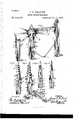
Millbrook, in the county of'Mecosta and Stateuseful Improvements in Devices for`Adjust of Michigan, have'invented certain new andV ing Spokes in YVagon-IIubs; and I do hereby declare that the following is a full, clear, and exact description of the invention, which will enable others skilled in the art to which it appertains to make and use the same, reference being had to the accompanying drawings, which form a part of this specification, and in which- Figure 1 is a perspective view of my improved machine for adjusting spokes in vehiclelhubs. Figs. 2, 3, 4, and 5 are sideviews of the central post, and Fig. 6 is a detail view of the adjustable prop for the hub.
spending parts in all the iigures.
My invention has relation 'to machines for adjusting spokes in vehicle-hubs; and it consist-s in the improved construction and arrangement of parts Vof the same, as hereinafter more fully described and claimed.
Similar letters of reference indicate corre!V In the accompanying drawings, the letter A indicates an upright post tapering toward the top, upon the upper end of which the hub is placed. A slotted flat bar, B, slides upon two, or more or less, screw-bolts, C, passing through the post, and providedwith thumbnuts D, bearing against the outer side of the bar, and
supports thehub from sliding down upon the 3 5 bar, the upper end of the slotted bar bearing l against the inner end of the hub under the sand-band, and a bar, E, having its upper end bent outward at a right angle, slides'in a ver: tical groove, F, in one of the other sides of the post, and isheld clamped to the post in the groove by a hooked clamp, G, clamping around the bar and passing with its screwthreaded end through the post, where it is provided, at the other side of the post, with a thumb-nut, H, by means of which the clamp may be drawn to clamp the bar tighter, or be released to allow the bar to slide freely. The upper bent end of this bar bears upon the upper end of the hub and preventsthe same 5o from `being raised off the post, and two ilat post, M, is placed at a distance from the post 6o 3 A, or the hub-supporting post, andis provided with a slotted plate, N, upon the side farthest f away from the hub-supporting post, which plate slides upon the ends of two, or more or less, bolts, O, passing through the post, and.
`provided with thumbnuts I), which bear against the plate and serve to adjust the same, and the upper end of this plate is flat, and may be brought to bear against the lower side or -edge ot a spoke inserted into its appro! priate socket in the hub, `serving to support the same `while being driven into the same. At the other side of the hub-supporting post, opposite to the spoke-supporting post, is placed another post, Q, which` has a number of notches, R, upon the side facing the hubsupporting post, into which the reduced shouldered or tenoned endS of a brace or prop, T, may be inserted; and `the said brace consists of alongitudinally-slotted tenoned portion, U, and an outer portion, V, having a coneaved and enlarged end, V, adapted to bear against the side or' the hub, and a reduced shouldered end, X, sliding in the slot inthe tenoned end. A pin or bolt, Y, passes through one of a series of perforations, Z, in the sides of the slot in the tenoned portion, and through one of a series of perforations, A, in the reduced end of the shouldered portion, thus hinging the two. portions together, and a plate, B', se-
.cured upon the under side of the reduced end,
and bearing with its sides against the lower edges against the sides of the slot, prevents the outer shouldered portion from swinging upward when the ends of the brace are braced against the notched post and against the hub, y u while a turn-button, C, upon vthe under side of the same end, but at the other side of the bolt, may be turned to bear against the lower edges of the sides of the slot or to `stand turned Ico 29ans upon the hubsupportingpost and secured from rocking upon the same, when the outer end of the spoke may be placed upon the upper end of thebarslidinguponthe spokesupportingpost, which bar has been adjusted at its proper height, when the spoke may be driven into its socket, and the prop, bearing against the hub and against the notched post, will offer resistance while the spoke is driveninto its socket.
Having thus described my invention, I claim and desire to secure by Letters Patent of the United States- E t,
l. In a machine for adjusting spokes in vehicle-hubs, a hub-supporting post having a slotted plate sliding adj ustably upon one side, having a' bar having its upper endvbent sliding in a vertical groove in the other side, having means i'or clamping it, and provided with two ilat bars secured at their upper ends to the upper end of the post, and having means for adjusting their lower ends nearer to and farther from the sides of the same, as and for the purpose shown andset forth;
2. The combination of a' 4hub-supporting post, an upright post having notches in the side facing the hub-supporting post, and a prop consisting of a tenoned portion adapted to engage one of the notches, and =-l1aving a longitudinal slot, a reduced shouldered portion adapted to "bear against vthe hub and to slide and rock in the slot, a bolt passing through a series of perforations in the sides of the slot and in the reduced end, and aturn-button and a plate attached to the under side of the reduced end, each at one side of the bolt, as and for the purpose shownand set forth. Y
8. A machine for adjusting spokes in vehicle-hubs, consisting of a hub-supporting post having means for holding the hub and for securing it from rocking, a post having a slotted bar sliding adjustably upon it, adapted to support the outer end of a spoke, a notched bar, and a jointed prop adapted to bear with one end into one of the notches and with the other end against the hub, as and for the purpose shown and set forth. y In testimony that I claim the foregoing as my own I have hereunto affixed my signature in presence of two witnesses. l
' JAMES II.` IIULBURT.
I lfiitliesses:
DAVID C. FULLER, ANDREW J. Dorn.
Publications (1)
| Publication Number | Publication Date |
|---|---|
| US293174A true US293174A (en) | 1884-02-05 |
Family
ID=2362361
Family Applications (1)
| Application Number | Title | Priority Date | Filing Date |
|---|---|---|---|
| US293174D Expired - Lifetime US293174A (en) | James h |
Country Status (1)
| Country | Link |
|---|---|
| US (1) | US293174A (en) |
-
0
- US US293174D patent/US293174A/en not_active Expired - Lifetime
Similar Documents
| Publication | Publication Date | Title |
|---|---|---|
| US298463A (en) | Roofing-bracket | |
| US293174A (en) | James h | |
| US517724A (en) | Screen | |
| US501521A (en) | marsh | |
| US8454A (en) | Improvement in saddles | |
| US226431A (en) | Mechanic s horse | |
| US6687A (en) | Bedstead-fastening | |
| US293673A (en) | rogers | |
| US194169A (en) | Improvement in umbrella-holders | |
| US121596A (en) | Improvement in extensible furniture | |
| US116857A (en) | Improvement in printers galley-rests | |
| US77273A (en) | Improved trestle | |
| US80106A (en) | Improved school seat and desk | |
| US381945A (en) | Joseph mortz | |
| US470066A (en) | Piano-stool | |
| US81440A (en) | Daniel f | |
| US351999A (en) | Folding clothes-bar | |
| US114720A (en) | Improvement in machines for tenoning spokes | |
| US115454A (en) | Ximprovement i in spring wagon-seats | |
| US198472A (en) | Improvement in mitering-machines | |
| US167588A (en) | Improvement in scaffolds | |
| US86924A (en) | Improvement in farm-fence | |
| US95602A (en) | notes | |
| US111878A (en) | Improvement in bedstead-fastenings | |
| US82054A (en) | Improved spue-wheel |