US2906554A - Magnetic lifting and material transferring devices - Google Patents
Magnetic lifting and material transferring devices Download PDFInfo
- Publication number
- US2906554A US2906554A US757992A US75799258A US2906554A US 2906554 A US2906554 A US 2906554A US 757992 A US757992 A US 757992A US 75799258 A US75799258 A US 75799258A US 2906554 A US2906554 A US 2906554A
- Authority
- US
- United States
- Prior art keywords
- main body
- body portion
- shield
- cable
- pair
- Prior art date
- Legal status (The legal status is an assumption and is not a legal conclusion. Google has not performed a legal analysis and makes no representation as to the accuracy of the status listed.)
- Expired - Lifetime
Links
- 239000000463 material Substances 0.000 title description 49
- 230000005291 magnetic effect Effects 0.000 title description 20
- 230000000694 effects Effects 0.000 description 10
- 239000000696 magnetic material Substances 0.000 description 8
- 230000003028 elevating effect Effects 0.000 description 5
- 229910001369 Brass Inorganic materials 0.000 description 2
- 239000010951 brass Substances 0.000 description 2
- 230000005484 gravity Effects 0.000 description 2
- 239000007787 solid Substances 0.000 description 2
- 229910001209 Low-carbon steel Inorganic materials 0.000 description 1
- 238000010276 construction Methods 0.000 description 1
- -1 for example Substances 0.000 description 1
- 238000004519 manufacturing process Methods 0.000 description 1
- 230000004048 modification Effects 0.000 description 1
- 238000012986 modification Methods 0.000 description 1
- 229920000136 polysorbate Polymers 0.000 description 1
- 230000003014 reinforcing effect Effects 0.000 description 1
- 239000010935 stainless steel Substances 0.000 description 1
- 229910001220 stainless steel Inorganic materials 0.000 description 1
Images
Classifications
-
- H—ELECTRICITY
- H01—ELECTRIC ELEMENTS
- H01F—MAGNETS; INDUCTANCES; TRANSFORMERS; SELECTION OF MATERIALS FOR THEIR MAGNETIC PROPERTIES
- H01F7/00—Magnets
- H01F7/06—Electromagnets; Actuators including electromagnets
- H01F7/20—Electromagnets; Actuators including electromagnets without armatures
- H01F7/206—Electromagnets for lifting, handling or transporting of magnetic pieces or material
-
- B—PERFORMING OPERATIONS; TRANSPORTING
- B66—HOISTING; LIFTING; HAULING
- B66C—CRANES; LOAD-ENGAGING ELEMENTS OR DEVICES FOR CRANES, CAPSTANS, WINCHES, OR TACKLES
- B66C1/00—Load-engaging elements or devices attached to lifting or lowering gear of cranes or adapted for connection therewith for transmitting lifting forces to articles or groups of articles
- B66C1/04—Load-engaging elements or devices attached to lifting or lowering gear of cranes or adapted for connection therewith for transmitting lifting forces to articles or groups of articles by magnetic means
Definitions
- This invention relates to material lifting and transfer devices, and more specifically, the instant invention pertains to material lifting and transfer means of a magnetic yp
- One of the primary objects of this invention is to provide a material lifting and transfer device employing one or more permanent magnets together with means for releasing materials lifted and transferred by said device.
- Another object of this invention is to provide a permanent magnet type of material elevating and transfer device, the permanent magnets being embedded within a base formed of a non-magnetic material.
- a further object of this invention is to provide a permanent magnet material elevating and transfer device, together with means for effecting the release of the material from the magnets, the means being interposed between the magnets and the material and being formed of a non-magnetic material.
- Still another object of the invention is to provide a permanent magnet-type material lifting and transfer device together with material release means which is operable to move the material attracted to the magnets out of the magnetic field thereof to effect its. release from the device.
- This invention contemplates, as a still further object thereof, the provision of a material elevating and transfer device of the permanent magnet-type, the device being non-complex in construction and assembly, inexpensive to manufacture, and durable in use.
- Figure l is a perspective view of a magnetic-type material elevating and transfer device constructed in acoordance with the teachings of one embodiment of this invention
- Figure 2 is a detail cross sectional view, partly in elevation, taken substantially on the vertical plane of line 22 of Figure 1, looking in the direction of the arrows;
- Figure 3 is a detail cross sectional view, partly in elevation, Figure 3 being taken substantially on the vertical plane of line 33 of Figure 2, looking in the direction of the arrows:
- Figure 4 is a bottom plan view of'the device illustrated in Figure l; v
- Figure 5 is a top plan view of a second embodiment of a material lifting and transfer device constructed in accordance with this invention.
- Figure 6 is a side elevational view of the modification shown in Figure '5;
- Figure 7 is an end elevational view of the material elevating and transfer device according to the second embodiment thereof, F igure 7 being partially broken away to illustrate certain component elements of the device;
- Figure 8 is a perspective view of a third embodiment of the instant invention.
- Figure 9 is an enlarged detail cross sectional view, part- 2,905,554 Patented Sept. 29, 1959 2 ly in elevation, taken substantially on the vertical plane of line 9-9 of Figure 8, looking in the direction of the arrows;
- Figure 10 is a perspective view of the device illustrated in Figure 8, Figure 10 illustrating the relative positions of the component elements of the device to effect material release;
- Figure 11 is an enlarged fragmentary detail cross sectional view taken substantially on line 1111 of Figure 10 looking in the direction of the arrows.
- reference numeral 20 designates, in general a permanent magnet type material lifting and transfer device constructed in accordance with the teachings of one embodiment of this invention.
- the device 20 is seen to comprise a substantially cylindrical solid main body portion or casing 22 provided with a plurality of radially spaced bores 24 and a centrally positioned bore 26, the bores 24, 26 extending transversely through the main body portion 22 from the top and bottom ends thereof.
- a substantially cylindrical bar-type permanent magnet 28 Disposed within each of the bores 24 is a substantially cylindrical bar-type permanent magnet 28, the lower ends of the magnets 28 being flush with the bottom end of the main body portion 22 while the upper ends thereof terminate flush with the lower end of a cylindrical recess 30.
- a discoidal cover plate 32 having a central aperture 34 is received within the recess 30 and substantially fills the same with the aperture 34 being coaxially aligned with the bore 26.
- the permanent magnets 23 may be press-fit or otherwise fixedly secured within their respective bores 24 or they may be otherwise fixedly secured therein by conventional means. Conventional means is also employed to fixedly secure the circumferential edge of the cover plate to adjacent areas of the main body portion 22.
- the latter, as well as the cover plate 32, are formed of non-magnetic material such as, for example, lead or brass. If preferred, the magnets 28 could be molded or cast in the main body portion 22.
- each'pair of the standards 36 having fixedly secured thereon and extending therebetween the opposed ends of pivot pins 38, and each of the latter are loosely received within elongated slots 40 formed in a pair of elongated actuating levers 42 adjacent one of their respective ends.
- Reference numeral 44 denotes an elongated substantially cylindrical shaft which is mounted for reciprocation through the bore 26 and aperture 34.
- two pair of substantially diametrically opposed lugs 46 project outwardly from the shaft 44 and disposed at the upper end thereof.
- the lugs 46 are laterally spaced from each other to receive and support the opposed ends of a pair of pivot pins 48.
- the pivot pins 48 pivotally connect the aforementioned one ends of the actuating levers 42 to the shaft 44.
- To the lower end of the shaft 44 is fixedly secured a discoidal shield 50 which is adapted, when in operative position, to fit flush across the lower ends of the magnets 28 and main body portion 22. Integral with the upper end of the shaft 44 is an open eye 52, the function of which will become more apparent below.
- the shaft 44 and the shield 50 are also formed of a non-magnetic material.
- Reference numeral 54 denotes a flexible cable that terminates in a closed loop 56 which is received within the open eye 52 of the shaft 44.
- the other end of the cable54 is trained about a pulley of a crane or other hoist (not shown) in such a manner that the operator thereof may pay out or reel in the cable 54 in exercising the functions of the device 20.
- the other ends of the levers 42 are apertured at 58 to receive therethrough closed loops 60 formed at one of the ends of the pair of flexible cables 62.
- the other ends of the cables 62 are joined by a connector 64 which is, in turn, connected to one end of a cable 66 the other end of the cable 66 is fitted over a pulley or drum of a conventional crane or hoist, in the manner described above, whereby the same may be payed out or reeled in under the control of an operator.
- the cable 54 is under tension and has drawn the shaft 44 upwardly through the bore 26 until the shield 50 abuts the lower end of the main body portion 22.
- the levers 42 have pivoted to their full line position illustrated in Figures 1 and 2 in the absence of tension of cable 62.
- the operator now manipulates the crane or hoist from which the device 20 depends to a position over the magnetizable material to be moved vand pays out both cables 54 and 66 until the shield 50 engages thereagainst.
- the magnetic fields of the permanent magnets 28 causes the material to adhere against the underside of the shield 50 and the cables 54 and 66 are then reeled in to effect an elevation of the magnetized material, care being exercised in reeling in the cable 66 to avoid tensioning the cables 62.
- the elevated magnetized material is moved to the site at which the same is to be deposited, and upon reaching this position, the operator reels in the cable 66 to such an extent as to cause the cable 62 to move upwardly therewith.
- the levers 42 pivot about their respective pins 38 to force the main body portion 22 to move upwardly relative to the shaft 44 thereby separating the shield 50 therefrom, the shield 50 assuming the dotted line position indicated in Figure 3 of the drawings.
- the degree of movement between the shield 50 and the main body portion 22 is of such extent to move the magnetized material out of the magnetic field to permit the same to drop from the shield 50 onto the desired transfer site.
- FIGS 5 to 7, inclusive illustrate a second embodiment of this invention wherein reference 100 designates, in general, a magnetic material lifter and transport device constructed in accordance with the teachings of a second embodiment of this invention.
- the device 100 is seen to comp-rise a substantially cylindrical main body portion or casing 102 formed of a non-magnetic material such as,.for example, lead orbrass and having fixedly embedded therein a centrally disposed cylindrical permanent bar magnet 104 having its longitudinal axis coaxially aligned with the longitudinal axis of the main body portion 102.
- the lower end of the main body portion 102 is formed with a circumferential bevel .106 to serve a function to be described, and the main body portion 102 has formed, integral with the upper end thereof, a pair of upright standards 108 which receive and support therein the opposed ends of a pivot pin 110 which extends therebetween.
- a pair of sleeves 112 Pivotally mounted on the pin 110, between the standards 108, are a pair of sleeves 112 to which are fixedly secured, respectively, a pair of elongated actuating levers 114 intermediate their respective ends.
- the ends 114A of the levers 114 are loosely engaged within vertically elongated slots 116 formed in the upper ends of a pair of vertically elongated, diametrically opposed, substantially rectangular bars 118 mounted for reciprocation within vertically spaced pairs of lugs 120 which are integral with or otherwise rigidly secured to the main body portion 102.
- the bars 118 have a length greater than the longitudinal axis of the-main body portion '102, and to the lower ends thereof is secured a shield 122 which may be formed of stainless steel, soft or low carbon steel, brass, or of other suitable and related materials.
- the shield 122 is recessed at 124 in such a manner as to provide a beveled side 126 adapted, under' one condition of operation of the device, to mate against the beveled end 106 of the main body portion 102.
- the cables 130, 134 are reeved over hoist pulleys (not shown) and are reeled on drums controlled by an operator. vAssuming that the device and its component elements are in the full line positions shown in Figure 6, and that the device is suspended over magnetizable material which is to be lifted and transported-to a new site, the cable 130 is reeled in to raise the ends 114A of the levers 114 to effect the closing of the shield 122 against the lower end of the main body portion 102 and the permanent magnet 104. Thereafter, the cables 130, 134 are payed out substantially simultaneously until the shield 122 engages the material to be lifted. The cables 128, 130 are then reeled in and the device 100 is moved to the site at which the material is to be deposited.
- the operator increases the tension on the cables 132, in the direction of the arrows, causing the ends 114B of levers 114 to pivot upwardly about the pivot pin to effect an elevation of the main body portion 102 relative to the shield 122.
- the relative movement of the main body portion 102 with respect to the shield 122 is of a sufiicient distance to diminish the efiective magnetic field to such an extent as to permit the material adhering to the shield 122 to be released therefrom and to drop into the new site.
- FIGS 8 to 11, inclusive, illustrate a third embodiment of this invention generally identified by reference numeral 200.
- the device 200 is seen to comprise a substantially solid cylindrical main body portion or casing 202 formedof a non-magnetizable material in which are embedded a plurality of cylindrical permanent bar magnets 204 which are radially spaced from one another. While the lower ends of the permanent magnets 204 are substantially flush with the end of the main body portion 202, the upper ends of the bar magnets 204 do not extend flush with the upper end of the main body portion 202.
- the cavity thus formed is filled with the metallic cap 206 formed of a non-magnetizable material.
- the main body portion 202 is formed with a central bore 208 and a coaxial upright integrally formed hollow boss 210.
- the boss 210 is provided with an axially extending key slot 212 which, at its lower end, is in open communication with one end of an axially extending key groove 214.
- the flange 218 is adapted to engage against the upper end of the boss 210 to limit the down- .ward movement of the shaft 216.
- an elongated shaft 216 having a radial flange 218 adjacent the upperend thereof.
- the shaft 216 is provided with a key 220 adapted to reciprocate within the key slot 212 and the key groove 214.
- the upper end of the shaft 216 is provided with an axially extending passage 222 which, at its lower end, is in open communication with a diametrically extending passage 224.
- the radial flange 218 is adapted to abut against the upper end of the boss 210 in order to limit the downward movement of the shaft 216.
- the lower end of the shaft 216 is necked down at 226 to receive thereon a substantially cylindrical flat centrally apertured shield 228, formed of the same material as the previously described shield.
- the shield 228 is provided with a plurality of radially extending circumferentially spaced reinforcing ribs 230 which are adapted to seat within grooves 232 formed in the lower end of the main body portion 202.
- the main body portion 202 is constructed with tapped openings 234 which receive the threaded ends of a pair of screws 236 to the upper ends of which are rigidly mounted a yoke 238 having opposed side walls 240, 242.
- the side walls 240, 242 support therebetween the opposed ends of a pair of pivot pins 244 on which are rotatablysupported, respectively, a pair of pulleys 246.
- One of the ends 248 of a pair of cables 250 are flexibly secured to the upper end of the shaft 216 by conventional means, and the other ends thereof are reeved around the pulleys 246 and are connected together by coupler 252 to a common cable 254.
- Reference numeral 256 denotes a cable having an end thereof extending through the passage 222 and bent to extend through either end of passage 224, this end of the cable 256 being knotted at 258 to prevent its withdrawal from the shaft 216.
- the device 200 is lowered to effect engagement of the shield 228 with the magnetizable material to be transported. Thereafter, the device 200 is elevated with the magnetizable material held against the shield 228 under the influence of the mag netic fields of force generated by the permanent magnets 204.
- the operator places increased tension on the cable 254 which, in turn, increases the tension on the cable 250 and drives the pulleys 246. As the pulleys 246 are driven the main body portion 202 is elevated relative to the shield 228.
- the extent of the movement of the main body portion 202 is suflicient to remove or diminish the magnetic field generated by the magnet 204 which previously exercised their influence on the material adhering to the shield 228. Consequently, the material is released from the shield 228 and falls under the force of gravity to the preselected site.
- the cables 250 are then released to return the main body portion to its operative position relative to the shield 228.
- the cables 62, 32 and 50 could be placed under tension to cause the main body portion 22, 102 and 202 to move relative to their respective shields 50, 122 and 228, where conversely, the main body portions could be held stationary and the cables 50, 130 and 256 could be released to prevent the shields 50, 122 and 228 to move downwardly relative thereto under the force of gravity until the material adhering thereto has moved out of the magnetic field,
- a magnetic lifting device for magnetizable materials comprising a casing having embedded therein means for generating a magnetic field, a shield mounted on said casing, said shield being normally disposed in said magnetic field intermediate said first means and said magnetizable material, and means on said casing connected with said shield to effect movement of said shield toward and away from said casing.
- a magnetic lifting device for magnetizable materials comprising a substantially cylindrical main body portion, said main body portion having a bore extending transversely therethrough, a shaft mounted for reciprocation within said bore and projecting beyond a pair of opposed ends of said main body portion, a plurality of bar-type permanent magnets disposed within said main body portion and circumferentially spaced around said bore, a pair of spaced standards fixedly secured to one end of said main body portion on diametrically opposed sides of said bore, a lever for each pair of said standards, means pivotally connecting each of said levers between said standards, means pivotally connecting one end of each of said levers to said shaft adjacent one end thereof, a shield extending across the other end of said main body portion, a lifting cable connected with said one end of said shaft for lifting said device, and a tripping cable connected with the other end of each of said levers, said tripping cable being operable to eifect pivotal movement of said levers and consequent relative movement between said main body portion and said shield.
- a magnetic lifting device for magnetizable materials comprising an elongated substantially cylindrical main body portion formed of a non-magnetic material, an elongated substantially cylindrical bar-type permanent magnet embedded within said main body portion, said main body portion having a pair of standards projecting from one end thereof in diametrically spaced relation, a pivot pin mounted on and extending between said standards, a pair of levers connected intermediate their respective ends on said pivot pin, a substantially cylindrical shield adapted for extension across the other end of said main body portion, a pair of bars having one of their respective ends connected to said shield at diametrically opposed points, a pair of axially spaced lugs projecting laterally from said main body portion on diametrically opposed sides thereof, said bars being positioned for reciprocation within said pairs of lugs, each of said bars at their other respective ends having an opening extending transversely therethrough, each of said levers having one of their respective ends loosely received in one of said openings, a lifting cable connected with said one end of said levers to close said shield against said
- a magnetic lifting device for magnetizable materials comprising a substantially cylindrical main body portion having a centrally disposed transversely extending bore, a plurality of permanent magnets of the bar-type embedded within said main body portion in circumferentially spaced relation relative to said bore, a shaft mounted for reciprocation in said bore, a shield connected with one end of said shaft and being adapted to extend across one end of said main body portion, means adjacent the other end of said shaft for limiting the movement thereof in one direction, means for preventing relative rotation between said main body portion and said shaft, a pair of diametrically opposed pulleys fixedly secured on the other end of said main body portion, a cable reeved around each of said pulleys and having one end thereof fixedly secured to the other end of said shaft, said cable comprising a tripping cable, and a lifting cable having one of its ends fixedly secured to said other end of said shaft, said lifting cable being operable to close said shield against said main body portion of said device and to lift said 7 shield and said main body portion as
- a magnetic lifting device for magnetizable materials comprising an elongated casing having a pair of opposed ends, a bar magnet embedded within said casing and having an end thereof substantially flush with one of said opi posed ends, a closure member extending across said one end of said casing, said closure member being formed of a non-magnetic material, and means supported on the other end of said casing for efiecting relative movement be: tween said casing and said closure member.
Landscapes
- Physics & Mathematics (AREA)
- Electromagnetism (AREA)
- Engineering & Computer Science (AREA)
- Power Engineering (AREA)
- Mechanical Engineering (AREA)
- Load-Engaging Elements For Cranes (AREA)
Description
Sept. 29, 1959 H. J. SJOSTROM MAGNETIC LIFTING AND MATERIAL TRANSFERRING DEVICES Filed Aug. 29, 1958 3 Sheets-Sheet 1 III] I [III I!!! l- FIG. 3.
mm N me e MN m w W s d W am a J/ M 1 H Sept. 29, 1959.
H. J. SJOSTRQM MAGNETIC LIFTING AND MATERIAL TRANSFERRING DEVICES Filed Aug. 29, 1958 3 Sheets-Sheet 2 FIG.
FIG. 6.
INVENTOR. HAQOLD c/. SJOSTEOM p 1959 H. J. SJOSTROM 2,906,554
MAGNETIC LIFTING AND MATERIAL TRANSFERRING DEVICES Filed Aug. 29, 1958 3 Sheets-Sheet 3 FIG. 9.
L fi
1 l 8 2oz i l I l L \\A\\ I I 2/4 225 2.72 234 rz2a 204 INVENTOR. 6448010 63/06? 80/14,
United States Patent MAGNETIC LIFTING AND MATERIAL TRANSFERRING DEVICES Harold J. Sjostrom, Pueblo, Colo. Application August 29, 1958, Serial No; 757,992 Claims. (Cl. 294-655) This invention relates to material lifting and transfer devices, and more specifically, the instant invention pertains to material lifting and transfer means of a magnetic yp One of the primary objects of this invention is to provide a material lifting and transfer device employing one or more permanent magnets together with means for releasing materials lifted and transferred by said device.
Another object of this invention is to provide a permanent magnet type of material elevating and transfer device, the permanent magnets being embedded within a base formed of a non-magnetic material.
A further object of this invention is to provide a permanent magnet material elevating and transfer device, together with means for effecting the release of the material from the magnets, the means being interposed between the magnets and the material and being formed of a non-magnetic material.
Still another object of the invention is to provide a permanent magnet-type material lifting and transfer device together with material release means which is operable to move the material attracted to the magnets out of the magnetic field thereof to effect its. release from the device.
This invention contemplates, as a still further object thereof, the provision of a material elevating and transfer device of the permanent magnet-type, the device being non-complex in construction and assembly, inexpensive to manufacture, and durable in use.
Other and further objects and advantages of the instant invention will become more manifest from a consideration of the annexed drawings, when read in conjunction with the following specification, in which:
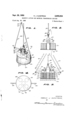
Figure l is a perspective view of a magnetic-type material elevating and transfer device constructed in acoordance with the teachings of one embodiment of this invention;
Figure 2 is a detail cross sectional view, partly in elevation, taken substantially on the vertical plane of line 22 of Figure 1, looking in the direction of the arrows;
Figure 3 is a detail cross sectional view, partly in elevation, Figure 3 being taken substantially on the vertical plane of line 33 of Figure 2, looking in the direction of the arrows:
Figure 4 is a bottom plan view of'the device illustrated in Figure l; v
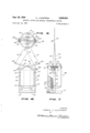
Figure 5 is a top plan view of a second embodiment of a material lifting and transfer device constructed in accordance with this invention;
Figure 6 is a side elevational view of the modification shown in Figure '5;
Figure 7 is an end elevational view of the material elevating and transfer device according to the second embodiment thereof, F igure 7 being partially broken away to illustrate certain component elements of the device;
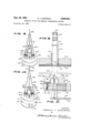
Figure 8 is a perspective view of a third embodiment of the instant invention;
Figure 9 is an enlarged detail cross sectional view, part- 2,905,554 Patented Sept. 29, 1959 2 ly in elevation, taken substantially on the vertical plane of line 9-9 of Figure 8, looking in the direction of the arrows;
Figure 10 is a perspective view of the device illustrated in Figure 8, Figure 10 illustrating the relative positions of the component elements of the device to effect material release; and
Figure 11 is an enlarged fragmentary detail cross sectional view taken substantially on line 1111 of Figure 10 looking in the direction of the arrows.
Referring more specifically to Figures 1 to 4, inclusive, reference numeral 20 designates, in general a permanent magnet type material lifting and transfer device constructed in accordance with the teachings of one embodiment of this invention. As illustrated in these figures, the device 20 is seen to comprise a substantially cylindrical solid main body portion or casing 22 provided with a plurality of radially spaced bores 24 and a centrally positioned bore 26, the bores 24, 26 extending transversely through the main body portion 22 from the top and bottom ends thereof.
Disposed within each of the bores 24 is a substantially cylindrical bar-type permanent magnet 28, the lower ends of the magnets 28 being flush with the bottom end of the main body portion 22 while the upper ends thereof terminate flush with the lower end of a cylindrical recess 30. A discoidal cover plate 32 having a central aperture 34 is received within the recess 30 and substantially fills the same with the aperture 34 being coaxially aligned with the bore 26.
The permanent magnets 23 may be press-fit or otherwise fixedly secured within their respective bores 24 or they may be otherwise fixedly secured therein by conventional means. Conventional means is also employed to fixedly secure the circumferential edge of the cover plate to adjacent areas of the main body portion 22. The latter, as well as the cover plate 32, are formed of non-magnetic material such as, for example, lead or brass. If preferred, the magnets 28 could be molded or cast in the main body portion 22.
To the upper sides of the main body portion 22 and the cover plate 32 is secured two pair of substantially diametrically opposed upright standards 36 with the standards of each pair being laterally spaced from each other, each'pair of the standards 36 having fixedly secured thereon and extending therebetween the opposed ends of pivot pins 38, and each of the latter are loosely received within elongated slots 40 formed in a pair of elongated actuating levers 42 adjacent one of their respective ends.
Reference numeral 44 denotes an elongated substantially cylindrical shaft which is mounted for reciprocation through the bore 26 and aperture 34. As is clearly seen in the drawings, two pair of substantially diametrically opposed lugs 46 project outwardly from the shaft 44 and disposed at the upper end thereof. The lugs 46 are laterally spaced from each other to receive and support the opposed ends of a pair of pivot pins 48. The pivot pins 48 pivotally connect the aforementioned one ends of the actuating levers 42 to the shaft 44. To the lower end of the shaft 44 is fixedly secured a discoidal shield 50 which is adapted, when in operative position, to fit flush across the lower ends of the magnets 28 and main body portion 22. Integral with the upper end of the shaft 44 is an open eye 52, the function of which will become more apparent below. The shaft 44 and the shield 50 are also formed of a non-magnetic material.
Reference numeral 54 denotes a flexible cable that terminates in a closed loop 56 which is received within the open eye 52 of the shaft 44. The other end of the cable54 is trained about a pulley of a crane or other hoist (not shown) in such a manner that the operator thereof may pay out or reel in the cable 54 in exercising the functions of the device 20.
As is clearly shown in Figure 3 of the drawings, the other ends of the levers 42 are apertured at 58 to receive therethrough closed loops 60 formed at one of the ends of the pair of flexible cables 62. The other ends of the cables 62 are joined by a connector 64 which is, in turn, connected to one end of a cable 66 the other end of the cable 66 is fitted over a pulley or drum of a conventional crane or hoist, in the manner described above, whereby the same may be payed out or reeled in under the control of an operator.
Referring now more specifically to Figure l of the drawings, the cable 54 is under tension and has drawn the shaft 44 upwardly through the bore 26 until the shield 50 abuts the lower end of the main body portion 22. The levers 42 have pivoted to their full line position illustrated in Figures 1 and 2 in the absence of tension of cable 62. The operator now manipulates the crane or hoist from which the device 20 depends to a position over the magnetizable material to be moved vand pays out both cables 54 and 66 until the shield 50 engages thereagainst. The magnetic fields of the permanent magnets 28 causes the material to adhere against the underside of the shield 50 and the cables 54 and 66 are then reeled in to effect an elevation of the magnetized material, care being exercised in reeling in the cable 66 to avoid tensioning the cables 62. The elevated magnetized material is moved to the site at which the same is to be deposited, and upon reaching this position, the operator reels in the cable 66 to such an extent as to cause the cable 62 to move upwardly therewith. As the cables 62 move upwardly, the levers 42 pivot about their respective pins 38 to force the main body portion 22 to move upwardly relative to the shaft 44 thereby separating the shield 50 therefrom, the shield 50 assuming the dotted line position indicated in Figure 3 of the drawings. The degree of movement between the shield 50 and the main body portion 22 is of such extent to move the magnetized material out of the magnetic field to permit the same to drop from the shield 50 onto the desired transfer site.
The operator then returns the device 10 into a position over the next load of material to be transferred and lowers the device 20 downwardly into engagement therewith. The shield 50 first engages the material, and the cables 54 and 66 are payed out until the component elements of the device 20 assume their relative positions as is illustrated in full lines in Figures 1 to 3, inclusive. Thereafter, the lifting and transfer operation is repeated as described supra.
Figures 5 to 7, inclusive, illustrate a second embodiment of this invention wherein reference 100 designates, in general, a magnetic material lifter and transport device constructed in accordance with the teachings of a second embodiment of this invention. The device 100 is seen to comp-rise a substantially cylindrical main body portion or casing 102 formed of a non-magnetic material such as,.for example, lead orbrass and having fixedly embedded therein a centrally disposed cylindrical permanent bar magnet 104 having its longitudinal axis coaxially aligned with the longitudinal axis of the main body portion 102. As is seen in Figures 6 and 7, the lower end of the main body portion 102 is formed with a circumferential bevel .106 to serve a function to be described, and the main body portion 102 has formed, integral with the upper end thereof, a pair of upright standards 108 which receive and support therein the opposed ends of a pivot pin 110 which extends therebetween.
Pivotally mounted on the pin 110, between the standards 108, are a pair of sleeves 112 to which are fixedly secured, respectively, a pair of elongated actuating levers 114 intermediate their respective ends. As is seen in 74 I the above referred to figures, the ends 114A of the levers 114 are loosely engaged within vertically elongated slots 116 formed in the upper ends of a pair of vertically elongated, diametrically opposed, substantially rectangular bars 118 mounted for reciprocation within vertically spaced pairs of lugs 120 which are integral with or otherwise rigidly secured to the main body portion 102. The bars 118 have a length greater than the longitudinal axis of the-main body portion '102, and to the lower ends thereof is secured a shield 122 which may be formed of stainless steel, soft or low carbon steel, brass, or of other suitable and related materials.
As is seen in Figures 6 and 7, the shield 122 is recessed at 124 in such a manner as to provide a beveled side 126 adapted, under' one condition of operation of the device, to mate against the beveled end 106 of the main body portion 102.
To the ends 114A of the levers 114 are secured one of the ends of a pair of flexible cables 128 (shown in dotted lines), the other ends of which are connected to a common flexible cable 130, the tension of which is controlled by the device operator to serve a function to be described. To the other ends 114B of the levers 114 are secured one of the ends of a pair of flexible cables 132 (shown in dotted lines), the other ends there- 'of being connected to a common lifting cable 134 (shown in dotted lines in Figure 7).
The cables 130, 134 are reeved over hoist pulleys (not shown) and are reeled on drums controlled by an operator. vAssuming that the device and its component elements are in the full line positions shown in Figure 6, and that the device is suspended over magnetizable material which is to be lifted and transported-to a new site, the cable 130 is reeled in to raise the ends 114A of the levers 114 to effect the closing of the shield 122 against the lower end of the main body portion 102 and the permanent magnet 104. Thereafter, the cables 130, 134 are payed out substantially simultaneously until the shield 122 engages the material to be lifted. The cables 128, 130 are then reeled in and the device 100 is moved to the site at which the material is to be deposited. Thereafter, the operator increases the tension on the cables 132, in the direction of the arrows, causing the ends 114B of levers 114 to pivot upwardly about the pivot pin to effect an elevation of the main body portion 102 relative to the shield 122. The relative movement of the main body portion 102 with respect to the shield 122 is of a sufiicient distance to diminish the efiective magnetic field to such an extent as to permit the material adhering to the shield 122 to be released therefrom and to drop into the new site.
Figures 8 to 11, inclusive, illustrate a third embodiment of this invention generally identified by reference numeral 200. The device 200 is seen to comprise a substantially solid cylindrical main body portion or casing 202 formedof a non-magnetizable material in which are embedded a plurality of cylindrical permanent bar magnets 204 which are radially spaced from one another. While the lower ends of the permanent magnets 204 are substantially flush with the end of the main body portion 202, the upper ends of the bar magnets 204 do not extend flush with the upper end of the main body portion 202. The cavity thus formed is filled with the metallic cap 206 formed of a non-magnetizable material. The main body portion 202 is formed with a central bore 208 and a coaxial upright integrally formed hollow boss 210. The boss 210 is provided with an axially extending key slot 212 which, at its lower end, is in open communication with one end of an axially extending key groove 214. The flange 218 is adapted to engage against the upper end of the boss 210 to limit the down- .ward movement of the shaft 216.
Mounted for reciprocation through the bore 208 is an elongated shaft 216 having a radial flange 218 adjacent the upperend thereof. The shaft 216 is provided with a key 220 adapted to reciprocate within the key slot 212 and the key groove 214. The upper end of the shaft 216 is provided with an axially extending passage 222 which, at its lower end, is in open communication with a diametrically extending passage 224. The radial flange 218 is adapted to abut against the upper end of the boss 210 in order to limit the downward movement of the shaft 216.
The lower end of the shaft 216 is necked down at 226 to receive thereon a substantially cylindrical flat centrally apertured shield 228, formed of the same material as the previously described shield. The shield 228 is provided with a plurality of radially extending circumferentially spaced reinforcing ribs 230 which are adapted to seat within grooves 232 formed in the lower end of the main body portion 202.
At diametrically opposed points, the main body portion 202 is constructed with tapped openings 234 which receive the threaded ends of a pair of screws 236 to the upper ends of which are rigidly mounted a yoke 238 having opposed side walls 240, 242. The side walls 240, 242 support therebetween the opposed ends of a pair of pivot pins 244 on which are rotatablysupported, respectively, a pair of pulleys 246.
One of the ends 248 of a pair of cables 250 are flexibly secured to the upper end of the shaft 216 by conventional means, and the other ends thereof are reeved around the pulleys 246 and are connected together by coupler 252 to a common cable 254.
Reference numeral 256 denotes a cable having an end thereof extending through the passage 222 and bent to extend through either end of passage 224, this end of the cable 256 being knotted at 258 to prevent its withdrawal from the shaft 216.
Assuming that the component elements of this embodiment of the invention are in their operative positions as is illustrated in Figure 8, the device 200 is lowered to effect engagement of the shield 228 with the magnetizable material to be transported. Thereafter, the device 200 is elevated with the magnetizable material held against the shield 228 under the influence of the mag netic fields of force generated by the permanent magnets 204. When the device 200 has been moved to a preselected site, the operator places increased tension on the cable 254 which, in turn, increases the tension on the cable 250 and drives the pulleys 246. As the pulleys 246 are driven the main body portion 202 is elevated relative to the shield 228. The extent of the movement of the main body portion 202 is suflicient to remove or diminish the magnetic field generated by the magnet 204 which previously exercised their influence on the material adhering to the shield 228. Consequently, the material is released from the shield 228 and falls under the force of gravity to the preselected site. The cables 250 are then released to return the main body portion to its operative position relative to the shield 228.
The sequential order of the operation of the above described embodiments of this invention need not necessarily be followed in order to obtain the release of the magnetizable material.
For example, in all cases, the cables 62, 32 and 50 could be placed under tension to cause the main body portion 22, 102 and 202 to move relative to their respective shields 50, 122 and 228, where conversely, the main body portions could be held stationary and the cables 50, 130 and 256 could be released to prevent the shields 50, 122 and 228 to move downwardly relative thereto under the force of gravity until the material adhering thereto has moved out of the magnetic field,
Having described and illustrated three embodiments of the instant invention, it will be understood that the same are offered merely by way of example, and that the instant invention is to be limited only by the scope of the appending claims.
What is claimed is:
l. A magnetic lifting device for magnetizable materials comprising a casing having embedded therein means for generating a magnetic field, a shield mounted on said casing, said shield being normally disposed in said magnetic field intermediate said first means and said magnetizable material, and means on said casing connected with said shield to effect movement of said shield toward and away from said casing.
2. A magnetic lifting device for magnetizable materials comprising a substantially cylindrical main body portion, said main body portion having a bore extending transversely therethrough, a shaft mounted for reciprocation within said bore and projecting beyond a pair of opposed ends of said main body portion, a plurality of bar-type permanent magnets disposed within said main body portion and circumferentially spaced around said bore, a pair of spaced standards fixedly secured to one end of said main body portion on diametrically opposed sides of said bore, a lever for each pair of said standards, means pivotally connecting each of said levers between said standards, means pivotally connecting one end of each of said levers to said shaft adjacent one end thereof, a shield extending across the other end of said main body portion, a lifting cable connected with said one end of said shaft for lifting said device, and a tripping cable connected with the other end of each of said levers, said tripping cable being operable to eifect pivotal movement of said levers and consequent relative movement between said main body portion and said shield.
3. A magnetic lifting device for magnetizable materials comprising an elongated substantially cylindrical main body portion formed of a non-magnetic material, an elongated substantially cylindrical bar-type permanent magnet embedded within said main body portion, said main body portion having a pair of standards projecting from one end thereof in diametrically spaced relation, a pivot pin mounted on and extending between said standards, a pair of levers connected intermediate their respective ends on said pivot pin, a substantially cylindrical shield adapted for extension across the other end of said main body portion, a pair of bars having one of their respective ends connected to said shield at diametrically opposed points, a pair of axially spaced lugs projecting laterally from said main body portion on diametrically opposed sides thereof, said bars being positioned for reciprocation within said pairs of lugs, each of said bars at their other respective ends having an opening extending transversely therethrough, each of said levers having one of their respective ends loosely received in one of said openings, a lifting cable connected with said one end of said levers to close said shield against said other end of said main body portion and to effect a lifting of said device, and a tripping cable connected to the other ends of said levers, said tripping cable being operable to effect relative movement between said shield and said main body portion.
47 A magnetic lifting device for magnetizable materials comprising a substantially cylindrical main body portion having a centrally disposed transversely extending bore, a plurality of permanent magnets of the bar-type embedded within said main body portion in circumferentially spaced relation relative to said bore, a shaft mounted for reciprocation in said bore, a shield connected with one end of said shaft and being adapted to extend across one end of said main body portion, means adjacent the other end of said shaft for limiting the movement thereof in one direction, means for preventing relative rotation between said main body portion and said shaft, a pair of diametrically opposed pulleys fixedly secured on the other end of said main body portion, a cable reeved around each of said pulleys and having one end thereof fixedly secured to the other end of said shaft, said cable comprising a tripping cable, and a lifting cable having one of its ends fixedly secured to said other end of said shaft, said lifting cable being operable to close said shield against said main body portion of said device and to lift said 7 shield and said main body portion as a unit, and said tripping cable being operable of effect relative movement between said main body portion and said shield.
5. A magnetic lifting device for magnetizable materials comprising an elongated casing having a pair of opposed ends, a bar magnet embedded within said casing and having an end thereof substantially flush with one of said opi posed ends, a closure member extending across said one end of said casing, said closure member being formed of a non-magnetic material, and means supported on the other end of said casing for efiecting relative movement be: tween said casing and said closure member.
References Cited in the file of this patent UNITED STATES PATENTS o, WWWM
Priority Applications (1)
| Application Number | Priority Date | Filing Date | Title |
|---|---|---|---|
| US757992A US2906554A (en) | 1958-08-29 | 1958-08-29 | Magnetic lifting and material transferring devices |
Applications Claiming Priority (1)
| Application Number | Priority Date | Filing Date | Title |
|---|---|---|---|
| US757992A US2906554A (en) | 1958-08-29 | 1958-08-29 | Magnetic lifting and material transferring devices |
Publications (1)
| Publication Number | Publication Date |
|---|---|
| US2906554A true US2906554A (en) | 1959-09-29 |
Family
ID=25050024
Family Applications (1)
| Application Number | Title | Priority Date | Filing Date |
|---|---|---|---|
| US757992A Expired - Lifetime US2906554A (en) | 1958-08-29 | 1958-08-29 | Magnetic lifting and material transferring devices |
Country Status (1)
| Country | Link |
|---|---|
| US (1) | US2906554A (en) |
Cited By (5)
| Publication number | Priority date | Publication date | Assignee | Title |
|---|---|---|---|---|
| US3009727A (en) * | 1957-11-27 | 1961-11-21 | Thew Shovel Co | Permanent magnet lifting device |
| US3198566A (en) * | 1963-07-17 | 1965-08-03 | Eriez Mfg Co | Material lifting device |
| DE2334446A1 (en) * | 1972-07-24 | 1974-02-07 | Inst Manipulacnich Dopravnich | METHOD AND DEVICE FOR SAFETY DURING LIFTING, CARRYING AND RELEASING FERROMAGNETIC LOADS AND A DEVICE TO DO SO |
| US4238095A (en) * | 1978-02-14 | 1980-12-09 | Hov-Air-Ship, Inc. | Method of and apparatus for anchoring airships and propulsion means for airships |
| US11235873B2 (en) * | 2018-03-22 | 2022-02-01 | King Abdullah University Of Science And Technology | Impulsive release mechanism and method |
Citations (5)
| Publication number | Priority date | Publication date | Assignee | Title |
|---|---|---|---|---|
| US1001689A (en) * | 1910-02-15 | 1911-08-29 | Arthur H Rogers | Stamp-handle. |
| US1685707A (en) * | 1927-09-15 | 1928-09-25 | Edward J Keedy | Toy magnetic crane |
| US2417762A (en) * | 1944-04-14 | 1947-03-18 | Koller Steven | Tool for magnetic lifting |
| US2623774A (en) * | 1950-01-26 | 1952-12-30 | Harold C Hubbard | Magnetic article grip for toy hoists |
| US2760809A (en) * | 1952-06-07 | 1956-08-28 | Ralph J Mallin | Devices for transferring magnetic materials |
-
1958
- 1958-08-29 US US757992A patent/US2906554A/en not_active Expired - Lifetime
Patent Citations (5)
| Publication number | Priority date | Publication date | Assignee | Title |
|---|---|---|---|---|
| US1001689A (en) * | 1910-02-15 | 1911-08-29 | Arthur H Rogers | Stamp-handle. |
| US1685707A (en) * | 1927-09-15 | 1928-09-25 | Edward J Keedy | Toy magnetic crane |
| US2417762A (en) * | 1944-04-14 | 1947-03-18 | Koller Steven | Tool for magnetic lifting |
| US2623774A (en) * | 1950-01-26 | 1952-12-30 | Harold C Hubbard | Magnetic article grip for toy hoists |
| US2760809A (en) * | 1952-06-07 | 1956-08-28 | Ralph J Mallin | Devices for transferring magnetic materials |
Cited By (5)
| Publication number | Priority date | Publication date | Assignee | Title |
|---|---|---|---|---|
| US3009727A (en) * | 1957-11-27 | 1961-11-21 | Thew Shovel Co | Permanent magnet lifting device |
| US3198566A (en) * | 1963-07-17 | 1965-08-03 | Eriez Mfg Co | Material lifting device |
| DE2334446A1 (en) * | 1972-07-24 | 1974-02-07 | Inst Manipulacnich Dopravnich | METHOD AND DEVICE FOR SAFETY DURING LIFTING, CARRYING AND RELEASING FERROMAGNETIC LOADS AND A DEVICE TO DO SO |
| US4238095A (en) * | 1978-02-14 | 1980-12-09 | Hov-Air-Ship, Inc. | Method of and apparatus for anchoring airships and propulsion means for airships |
| US11235873B2 (en) * | 2018-03-22 | 2022-02-01 | King Abdullah University Of Science And Technology | Impulsive release mechanism and method |
Similar Documents
| Publication | Publication Date | Title |
|---|---|---|
| US2906554A (en) | Magnetic lifting and material transferring devices | |
| EP0347626A2 (en) | Lever-type yarn guide device operated by a linear motor, for textile machines | |
| US3009727A (en) | Permanent magnet lifting device | |
| US2989666A (en) | Selective control valve | |
| US3032363A (en) | Magnetic tie plate lifter | |
| US2505904A (en) | Holding relay with permanent magnet | |
| CN109227590B (en) | A magnetic fluid mechanical gripper | |
| CN113675037B (en) | A load switching device and method thereof | |
| US2721904A (en) | Driving apparatus | |
| US1818584A (en) | Lifting device | |
| US2239750A (en) | Device of the crane type for the loading and unloading of magnetic materials | |
| ES347039A1 (en) | Knitting machines | |
| US2879618A (en) | Retriever for an underwater object | |
| US2588837A (en) | Automatic fishing reel brake | |
| US2493386A (en) | Antivibration plunger type electromagnet | |
| CN109659196A (en) | Trip free relay | |
| US2643477A (en) | Fish catching apparatus | |
| US2462482A (en) | Electromagnet with plunger | |
| US2219244A (en) | Current connection ring | |
| US4056257A (en) | Hoisting tackle block assembly | |
| US2447343A (en) | Electromagnet positioning device | |
| US2370038A (en) | Latched-in magnetic switch | |
| US2140700A (en) | Lifting magnet | |
| RU1776619C (en) | Magnetic grab | |
| US2514012A (en) | Current-limiting and protective arrangement |