US2884313A - Method of removing an electrically conducting film - Google Patents
Method of removing an electrically conducting film Download PDFInfo
- Publication number
- US2884313A US2884313A US532889A US53288955A US2884313A US 2884313 A US2884313 A US 2884313A US 532889 A US532889 A US 532889A US 53288955 A US53288955 A US 53288955A US 2884313 A US2884313 A US 2884313A
- Authority
- US
- United States
- Prior art keywords
- film
- electrically conducting
- electrode
- organic liquid
- conducting film
- Prior art date
- Legal status (The legal status is an assumption and is not a legal conclusion. Google has not performed a legal analysis and makes no representation as to the accuracy of the status listed.)
- Expired - Lifetime
Links
- 238000000034 method Methods 0.000 title claims description 20
- 239000007788 liquid Substances 0.000 claims description 20
- 229910001887 tin oxide Inorganic materials 0.000 claims description 14
- 239000011248 coating agent Substances 0.000 claims description 11
- 238000000576 coating method Methods 0.000 claims description 11
- 229910010293 ceramic material Inorganic materials 0.000 claims description 7
- ATJFFYVFTNAWJD-UHFFFAOYSA-N Tin Chemical compound [Sn] ATJFFYVFTNAWJD-UHFFFAOYSA-N 0.000 claims description 5
- 239000002253 acid Substances 0.000 claims description 3
- DDSPUNTXKUFWTM-UHFFFAOYSA-N oxygen(2-);tin(4+) Chemical compound [O-2].[O-2].[Sn+4] DDSPUNTXKUFWTM-UHFFFAOYSA-N 0.000 claims 1
- OKTJSMMVPCPJKN-UHFFFAOYSA-N Carbon Chemical compound [C] OKTJSMMVPCPJKN-UHFFFAOYSA-N 0.000 description 19
- PEDCQBHIVMGVHV-UHFFFAOYSA-N Glycerine Chemical compound OCC(O)CO PEDCQBHIVMGVHV-UHFFFAOYSA-N 0.000 description 16
- XOLBLPGZBRYERU-UHFFFAOYSA-N tin dioxide Chemical compound O=[Sn]=O XOLBLPGZBRYERU-UHFFFAOYSA-N 0.000 description 13
- 229910052799 carbon Inorganic materials 0.000 description 10
- 229910002804 graphite Inorganic materials 0.000 description 9
- 239000010439 graphite Substances 0.000 description 9
- 239000011521 glass Substances 0.000 description 8
- 235000011187 glycerol Nutrition 0.000 description 8
- 239000000463 material Substances 0.000 description 4
- 229910044991 metal oxide Inorganic materials 0.000 description 4
- 150000004706 metal oxides Chemical class 0.000 description 4
- 239000011368 organic material Substances 0.000 description 3
- 239000000919 ceramic Substances 0.000 description 2
- 238000012217 deletion Methods 0.000 description 2
- 230000037430 deletion Effects 0.000 description 2
- WABPQHHGFIMREM-UHFFFAOYSA-N lead(0) Chemical compound [Pb] WABPQHHGFIMREM-UHFFFAOYSA-N 0.000 description 2
- UFHFLCQGNIYNRP-UHFFFAOYSA-N Hydrogen Chemical compound [H][H] UFHFLCQGNIYNRP-UHFFFAOYSA-N 0.000 description 1
- BQCADISMDOOEFD-UHFFFAOYSA-N Silver Chemical compound [Ag] BQCADISMDOOEFD-UHFFFAOYSA-N 0.000 description 1
- 229910021627 Tin(IV) chloride Inorganic materials 0.000 description 1
- 208000027418 Wounds and injury Diseases 0.000 description 1
- 230000015572 biosynthetic process Effects 0.000 description 1
- 239000004020 conductor Substances 0.000 description 1
- 230000006378 damage Effects 0.000 description 1
- 238000000354 decomposition reaction Methods 0.000 description 1
- 229910052739 hydrogen Inorganic materials 0.000 description 1
- 239000001257 hydrogen Substances 0.000 description 1
- 208000014674 injury Diseases 0.000 description 1
- 238000004519 manufacturing process Methods 0.000 description 1
- 229910052751 metal Inorganic materials 0.000 description 1
- 239000002184 metal Substances 0.000 description 1
- 235000019645 odor Nutrition 0.000 description 1
- 229910052709 silver Inorganic materials 0.000 description 1
- 239000004332 silver Substances 0.000 description 1
- 150000003606 tin compounds Chemical class 0.000 description 1
- HPGGPRDJHPYFRM-UHFFFAOYSA-J tin(iv) chloride Chemical compound Cl[Sn](Cl)(Cl)Cl HPGGPRDJHPYFRM-UHFFFAOYSA-J 0.000 description 1
Images
Classifications
-
- B—PERFORMING OPERATIONS; TRANSPORTING
- B41—PRINTING; LINING MACHINES; TYPEWRITERS; STAMPS
- B41M—PRINTING, DUPLICATING, MARKING, OR COPYING PROCESSES; COLOUR PRINTING
- B41M5/00—Duplicating or marking methods; Sheet materials for use therein
- B41M5/24—Ablative recording, e.g. by burning marks; Spark recording
- B41M5/245—Electroerosion or spark recording
-
- H—ELECTRICITY
- H01—ELECTRIC ELEMENTS
- H01B—CABLES; CONDUCTORS; INSULATORS; SELECTION OF MATERIALS FOR THEIR CONDUCTIVE, INSULATING OR DIELECTRIC PROPERTIES
- H01B1/00—Conductors or conductive bodies characterised by the conductive materials; Selection of materials as conductors
Definitions
- the present invention is particularly applicable in providing a plurality of areas of electrically conducting films which are separated by nonconducting areas which are in the form of thin lines.
- Another object of this invention is the provision of a method of removing such films in the form of a narrow line by electrical means.
- a further object is the provision of a method of removing a line of electrically conducting material in which the removal may be done accurately and quickly and in which the line removed is of a uniform width throughout.
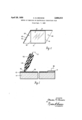
- Fig. 1 is a diagrammatic showing of a preferred form of the method in which my invention may be carried out.
- Fig. 2 is a perspective view illustrating a sheet of glass having a transparent electrically conducting film in which lines have been deleted therefrom according to this invention.
- an electrically conducting film may have a portion thereof deleted in the form of a line by coating the film with an organic liquid, applying an electric potential between the film and an electrode, and contacting the electrically conducting film with the electrode.
- an organic liquid acts as a dielectric and that an arc travels therethrough due to the electric potential between the electrode and the electrically conducting film.
- This arc probably causes a decomposition of the organic material in which hydrogen is formed or at least reducing conditions are provided so that the tin oxide film is reduced to metallic tin.
- the remaining metallic tin is substantially nonconducting but, if desired, it may be removed with a dilute acid solution.
- a light of glass 10 having a fired-on electrode 11 and an electrically conducting film 12 of a metal oxide and preferably tin oxide.
- an organic material 13 such as glycerin is brushed, sprayed or otherwise applied over the film 12.
- a carbon electrode 14 is sharpened to a point 15 having a width corresponding to the desired width of the line of material to be deleted.
- an ordinary graphite pencil may be used having a rod for the electrode 14 and a wooden case 16 which encloses the electrode 14.
- a direct current is used, and the carbon electrode is connected to the positive post through lead wire 17, and the bus bar or fired-on silver strip 11 is connected to the negative post of the direct current supply through lead wire 18.
- the film may be deleted when the electrical connection is in the reverse of that given or even when an alternating current is applied.
- the carbon electrode is placed in contacted position, as shown in Fig. 1, and moved over the surface 12 to form a line of deleted electrical conducting film in the desired pattern.
- any organic liquid may be used, but some are superior to others.
- light oil may be used but it is not so easily removed as glycerin.
- Other operable materials may have disagreeable odors or create a. fire hazard or for other reasons be inferior to glycerin, but it is to be understood that such materials may be used in the practice of this invention.
- carbon is used for the electrode although other materials may be used. Carbon has the advantage of being easily sharpened to the desired width.
- the voltage must be sufficient to produce an are through the organic material, but excessive voltages should be avoided due to excessive temperatures produced thereby.
- the voltage used is between 25 and volts.
- Fig. 2 there is shown light of glass having lines 19 deleted thereon to form separate areas 20, 21 and 22 of electrically conducting film.
- Such lights of glass are used in the aircraft industry and the illustrated shape is often used.
- Lights having portions deleted therefrom are also proposed for use in automobiles. In such situations, the whole light is filmed with tin oxide to provide a light of a uniform appearance.
- the lines 19 are narrow enough so that the uniform appearance is maintained while at the same time the area 21 is uniformly heated to prevent frost formation or remove the same in the critical area.
- a method of removing selected portions of an electrically conducting metal oxide film from ceramic material comprising, coating the film with a dielectric organic liquid, establishing a voltage between an electrode and the metal oxide film, and contacting the organic liquid overlying the metal oxide film with the electrode.
- a method of removing selected portions of an electrically conducting tin oxide film from ceramic material comprising, coating the film with a dielectric organic liquid, establishing a voltage between a carbon electrode and the electrically conducting film, and contacting the organic liquid with the carbon electrode.
- a method of removing selected portions of an electrically conducting tin oxide film from ceramic material comprising, coating the film with a dielectric organic liquid, establishing a voltage of between 25 and 100 volts between a graphite electrode and the electrically conducting film, and contacting the organic liquid with the graphite electrode.
- a method of removing selected portions of an electrically conducting tin oxide film from ceramic material comprising, coating the film with a dielectric organic liquid, establishing a voltage of between 25 and 100 volts between a sharpened graphite electrode and the electrically conducting film, contacting the organic liquid with the graphite electrode, and moving the electrode lineally over the surface of the organic liquid.
- a method of removing selected portions of an electrically conducting tin oxide film from ceramic material comprising, coating the film with a dielectric organic liquid, establishing a direct current voltage of between 25 and volts between a sharpened graphite electrode and the electrically conducting film, the electrode being connected to the positive post of the direct current source and the film being connected to the negative post of the direct current source, contacting the organic liquid with the graphite electrode, and moving the electrode lineally over the surface of the organic liquid.
- a method of removing selected portions of an electrically conducting tin oxide film from a ceramic body comprising, coating the film with glycerin, establishing a voltage between a carbon electrode and the electrically conducting film, and contacting the exposed surface of the glycerin with the carbon electrode.
- a method of removing selected portions of an electrically conducting tin oxide film from a ceramic body comprising, coating the film with glycerin, establishing a voltage of between 25 and 100 volts between a graphite electrode having a sharpened point and the electrically conducting film, and contacting the exposed surface of the glycerin with the point of the graphite electrode.
- a method of removing selected portions of an electrically conducting tin oxide film from ceramic material comprising coating the film with a dielectric organic liquid, establishing a voltage between an electrode and the electrically conducting film, contacting the organic liquid on the film with the electrode and moving the same lineally over the surface of the film to reduce a line of tin oxide substantially to metallic tin, and subjecting the film to an acid solution to remove the newly formed tin metal.
Landscapes
- Surface Treatment Of Glass (AREA)
Description
April 28, 1959 c. BROWNE 2,884,313
METHOD OF REMOVING AN ELECTRICALLY CONDUCTING FILM Filed Sept. '7, 1955 INVENTOR.
Chad. 520mm BY awe {drama A TTORNE YS United States Patent METHOD OF REMOVING AN ELECTRICALLY CONDUCTING FILM Charles M. Browne, Toledo, Ohio, assignor to Libbey- Owens-Ford Glass Company, Toledo, Ohio, a corporation of Ohio Application September 7, 1955, Serial No. 532,889
9 Claims. (Cl. 4143) of softening, with tin tetrachloride or other suitable tin compounds to produce a film primarily of a tin oxide which is electrically conducting. One of the characteristics of these films is their extremely tight adherence to vitreous surfaces, like glass, when applied thereto. In fact, it has been said that a properly applied electrically conducting coating of tin oxide on a glass sheet is very nearly as hard and'as difiicult to remove as the glass surface itself.
Nevertheless, it is very often necessary in the production of glass articles provided with such a film to remove selected strips or areas of the'film" to facilitate testing of the unit, to improve its appearance or utility, or to control or regulate the conductivity of the filmed surface.
The present invention is particularly applicable in providing a plurality of areas of electrically conducting films which are separated by nonconducting areas which are in the form of thin lines. 1
It is a primary object of this invention to provide a method for removing films of the above character quickly and without injury to the supporting surface.
Another object of this invention is the provision of a method of removing such films in the form of a narrow line by electrical means.
A further object is the provision of a method of removing a line of electrically conducting material in which the removal may be done accurately and quickly and in which the line removed is of a uniform width throughout.
Other objects and advantages of the invention will become more apparent during the course of the following description, when taken in connection with the accompanying drawings.
In the drawings, wherein like numerals are employed to designate like parts throughout the same:
Fig. 1 is a diagrammatic showing of a preferred form of the method in which my invention may be carried out; and
Fig. 2 is a perspective view illustrating a sheet of glass having a transparent electrically conducting film in which lines have been deleted therefrom according to this invention.
Generally stated, my invention is based on the discovery that an electrically conducting film may have a portion thereof deleted in the form of a line by coating the film with an organic liquid, applying an electric potential between the film and an electrode, and contacting the electrically conducting film with the electrode. In order 2,884,313 Patented Apr. 28, 1959 to remove the film in the form of a line it is only necessary to move the electrode over the electrically conducting film at a writing speed. It is not known exactly how the deletion is accomplished, but it is believed that the organic liquid acts as a dielectric and that an arc travels therethrough due to the electric potential between the electrode and the electrically conducting film. This arc probably causes a decomposition of the organic material in which hydrogen is formed or at least reducing conditions are provided so that the tin oxide film is reduced to metallic tin. The remaining metallic tin is substantially nonconducting but, if desired, it may be removed with a dilute acid solution.
In Fig. 1 there is shown a light of glass 10 having a fired-on electrode 11 and an electrically conducting film 12 of a metal oxide and preferably tin oxide. In order to remove a portion of the electrically conducting film 12 a layer of an organic material 13 such as glycerin is brushed, sprayed or otherwise applied over the film 12. A carbon electrode 14 is sharpened to a point 15 having a width corresponding to the desired width of the line of material to be deleted. In fact, an ordinary graphite pencil may be used having a rod for the electrode 14 and a wooden case 16 which encloses the electrode 14. Preferably, a direct current is used, and the carbon electrode is connected to the positive post through lead wire 17, and the bus bar or fired-on silver strip 11 is connected to the negative post of the direct current supply through lead wire 18. However, the film may be deleted when the electrical connection is in the reverse of that given or even when an alternating current is applied. After the electric potential has been connected, the carbon electrode is placed in contacted position, as shown in Fig. 1, and moved over the surface 12 to form a line of deleted electrical conducting film in the desired pattern.
Generally, any organic liquid may be used, but some are superior to others. For example, light oil may be used but it is not so easily removed as glycerin. Other operable materials may have disagreeable odors or create a. fire hazard or for other reasons be inferior to glycerin, but it is to be understood that such materials may be used in the practice of this invention.
Preferably, carbon is used for the electrode although other materials may be used. Carbon has the advantage of being easily sharpened to the desired width.
The voltage must be sufficient to produce an are through the organic material, but excessive voltages should be avoided due to excessive temperatures produced thereby. Preferably, the voltage used is between 25 and volts.
In Fig. 2, there is shown light of glass having lines 19 deleted thereon to form separate areas 20, 21 and 22 of electrically conducting film. Such lights of glass are used in the aircraft industry and the illustrated shape is often used. Lights having portions deleted therefrom are also proposed for use in automobiles. In such situations, the whole light is filmed with tin oxide to provide a light of a uniform appearance. The lines 19 are narrow enough so that the uniform appearance is maintained while at the same time the area 21 is uniformly heated to prevent frost formation or remove the same in the critical area.
It is contemplated that other uses may be made of the present deletion method, and it is to be understood that the use illustrated in Fig. 2 is not to be construed as the only use to which this method is applicable.
Although this method of deleting a portion of an electrically conducting film is particularly valuable in deleting an area in the form of a line, it is to be understood other areas may be deleted simply by moving the carbon electrode to delete juxtaposed parallel lines so that an area of unlimited width may be formed, or that a line may be formed in such a way that an area is enclosed within the line which is completely set off from the main electrically conducting film. It has been found that a line may be traced in the form of a circle and that the resistance between the film on the inside of the circle and the film outside the circle is in the range of megohms. Accordingly, areas may be deleted as well as lines.
It is to be understood that the forms of the invention herewith shown and described are to be taken as illustrative embodiments only of the same, and that various procedural changes may be resorted, to without departing from the spirit of the invention or the scope of the subjoined claims.
I claim:
1. A method of removing selected portions of an electrically conducting metal oxide film from ceramic material comprising, coating the film with a dielectric organic liquid, establishing a voltage between an electrode and the metal oxide film, and contacting the organic liquid overlying the metal oxide film with the electrode.
2. A method of removing selected portions of an electrically conducting tin oxide film from ceramic material comprising, coating the film with a dielectric organic liquid, establishing a voltage between a carbon electrode and the electrically conducting film, and contacting the organic liquid with the carbon electrode.
3. A method of removing selected portions of an electrically conducting tin oxide film from ceramic material comprising, coating the film with a dielectric organic liquid, establishing a voltage of between 25 and 100 volts between a graphite electrode and the electrically conducting film, and contacting the organic liquid with the graphite electrode.
4. A method of removing selected portions of an electrically conducting tin oxide film from ceramic material comprising, coating the film with a dielectric organic liquid, establishing a voltage of between 25 and 100 volts between a sharpened graphite electrode and the electrically conducting film, contacting the organic liquid with the graphite electrode, and moving the electrode lineally over the surface of the organic liquid.
5. A method of removing selected portions of an electrically conducting tin oxide film from ceramic material comprising, coating the film with a dielectric organic liquid, establishing a direct current voltage of between 25 and volts between a sharpened graphite electrode and the electrically conducting film, the electrode being connected to the positive post of the direct current source and the film being connected to the negative post of the direct current source, contacting the organic liquid with the graphite electrode, and moving the electrode lineally over the surface of the organic liquid.
6. A method of removing selected portions of an electrically conducting tin oxide film from a ceramic body comprising, coating the film with glycerin, establishing a voltage between a carbon electrode and the electrically conducting film, and contacting the exposed surface of the glycerin with the carbon electrode.
7. A method of removing selected portions of an electrically conducting tin oxide film from a ceramic body comprising, coating the film with glycerin, establishing a voltage of between 25 and 100 volts between a graphite electrode having a sharpened point and the electrically conducting film, and contacting the exposed surface of the glycerin with the point of the graphite electrode.
8. A method of removing selected portions of an electrically conducting tin oxide film from ceramic material, comprising coating the film with a dielectric organic liquid, establishing a voltage between an electrode and the electrically conducting film, contacting the organic liquid on the film with the electrode and moving the same lineally over the surface of the film to reduce a line of tin oxide substantially to metallic tin, and subjecting the film to an acid solution to remove the newly formed tin metal.
9. A method of removing an electrically conducting film as defined in claim 8, in which the organic liquid is glycerin.
References Cited in the file of this patent UNITED STATES PATENTS 2,248,057 Bond July 8, 1941 2,486,281 Henry Oct. 25, 1949 2,513,838 Beall July 4, 1950 2,722,511 Butler et a1. Nov. 1, 1955 2,739,112 Ferguson Mar. 20, 1956 FOREIGN PATENTS 637,793 Great Britain May 24, 1950 718,442 Great Britain Nov. 17, 1954
Claims (1)
- 8. A METHOD OF REMOVING SELECTED PORTIONS OF AN ELECTRICALLY CONDUCTING TIN OXIDE FILM FROM CERAMIC MATERIAL, COMPRISING COATING THE FILM WITH A DIELECTRIC ORGANIC LIQUID, ESTABLISHING A VOLTAGE BETWEEN AN ELECTRODE AND THE ELECTRICALLY CONDUCTING FILM, CONTACTING THE ORGANIC LIQUID ON THE FILM WITH THE ELECTRODE AND MOVING THE SAME LINEALLY OVER THE SURFACE OF THE FILM TO REDUCE A LINE OF OXIDE SUBSTANTIALLY TO METALLIC TIN, AND SUBJECTING THE FILM TO AN ACID SOLUTION TO REMOVE THE NEWLY FORMED TIN METAL.
Priority Applications (1)
| Application Number | Priority Date | Filing Date | Title |
|---|---|---|---|
| US532889A US2884313A (en) | 1955-09-07 | 1955-09-07 | Method of removing an electrically conducting film |
Applications Claiming Priority (1)
| Application Number | Priority Date | Filing Date | Title |
|---|---|---|---|
| US532889A US2884313A (en) | 1955-09-07 | 1955-09-07 | Method of removing an electrically conducting film |
Publications (1)
| Publication Number | Publication Date |
|---|---|
| US2884313A true US2884313A (en) | 1959-04-28 |
Family
ID=24123607
Family Applications (1)
| Application Number | Title | Priority Date | Filing Date |
|---|---|---|---|
| US532889A Expired - Lifetime US2884313A (en) | 1955-09-07 | 1955-09-07 | Method of removing an electrically conducting film |
Country Status (1)
| Country | Link |
|---|---|
| US (1) | US2884313A (en) |
Cited By (9)
| Publication number | Priority date | Publication date | Assignee | Title |
|---|---|---|---|---|
| US3084245A (en) * | 1958-10-24 | 1963-04-02 | Raffinage Cie Francaise | Electro-discharge machining of metals and the like |
| US3168638A (en) * | 1962-06-14 | 1965-02-02 | Cincinnati Milling Machine Co | Method of electro-discharge machining and fluids for use therein |
| US3205155A (en) * | 1961-10-19 | 1965-09-07 | Motorola Inc | Method of fabricating thin film resistive elements |
| US3324276A (en) * | 1962-04-19 | 1967-06-06 | Philips Corp | Spark erosion apparatus and method of removing thin metal layers |
| US3440388A (en) * | 1966-04-04 | 1969-04-22 | Monsanto Co | Method for machining with laser beam |
| US3463898A (en) * | 1965-07-09 | 1969-08-26 | Tokyo Shibaura Electric Co | Welding device utilizing laser beams |
| US3775274A (en) * | 1970-06-30 | 1973-11-27 | Hughes Aircraft Co | Electrolytic anticompromise process |
| US3935333A (en) * | 1971-12-18 | 1976-01-27 | Kansai Paint Company, Ltd. | Method for forming a transparent image on a sheet |
| US4536633A (en) * | 1980-02-18 | 1985-08-20 | Mitsubishi Denki Kabushiki Kaisha | Dielectric fluid for electrical discharge machining |
Citations (7)
| Publication number | Priority date | Publication date | Assignee | Title |
|---|---|---|---|---|
| US2248057A (en) * | 1939-01-25 | 1941-07-08 | Bell Telephone Labor Inc | Electrical cutting device |
| US2486281A (en) * | 1948-12-22 | 1949-10-25 | Valley Mould & Iron Corp | Arc cutting of metal and electrode therefor |
| GB637793A (en) * | 1946-09-24 | 1950-05-24 | Boris Romanovitch Lazarenko | A method of working metals and other electro-conductive materials and means for applying same |
| US2513838A (en) * | 1946-07-11 | 1950-07-04 | Herbert W Beall | Method of making porous fabric |
| GB718442A (en) * | 1951-11-29 | 1954-11-17 | Bradley And Foster Ltd | Improvements in or relating to machining metals and alloys by the electro-erosion method |
| US2722511A (en) * | 1952-11-28 | 1955-11-01 | Sylvania Electric Prod | Method of removing conductive coating |
| US2739112A (en) * | 1952-04-08 | 1956-03-20 | Ferguson Carl | Decoating process |
-
1955
- 1955-09-07 US US532889A patent/US2884313A/en not_active Expired - Lifetime
Patent Citations (7)
| Publication number | Priority date | Publication date | Assignee | Title |
|---|---|---|---|---|
| US2248057A (en) * | 1939-01-25 | 1941-07-08 | Bell Telephone Labor Inc | Electrical cutting device |
| US2513838A (en) * | 1946-07-11 | 1950-07-04 | Herbert W Beall | Method of making porous fabric |
| GB637793A (en) * | 1946-09-24 | 1950-05-24 | Boris Romanovitch Lazarenko | A method of working metals and other electro-conductive materials and means for applying same |
| US2486281A (en) * | 1948-12-22 | 1949-10-25 | Valley Mould & Iron Corp | Arc cutting of metal and electrode therefor |
| GB718442A (en) * | 1951-11-29 | 1954-11-17 | Bradley And Foster Ltd | Improvements in or relating to machining metals and alloys by the electro-erosion method |
| US2739112A (en) * | 1952-04-08 | 1956-03-20 | Ferguson Carl | Decoating process |
| US2722511A (en) * | 1952-11-28 | 1955-11-01 | Sylvania Electric Prod | Method of removing conductive coating |
Cited By (9)
| Publication number | Priority date | Publication date | Assignee | Title |
|---|---|---|---|---|
| US3084245A (en) * | 1958-10-24 | 1963-04-02 | Raffinage Cie Francaise | Electro-discharge machining of metals and the like |
| US3205155A (en) * | 1961-10-19 | 1965-09-07 | Motorola Inc | Method of fabricating thin film resistive elements |
| US3324276A (en) * | 1962-04-19 | 1967-06-06 | Philips Corp | Spark erosion apparatus and method of removing thin metal layers |
| US3168638A (en) * | 1962-06-14 | 1965-02-02 | Cincinnati Milling Machine Co | Method of electro-discharge machining and fluids for use therein |
| US3463898A (en) * | 1965-07-09 | 1969-08-26 | Tokyo Shibaura Electric Co | Welding device utilizing laser beams |
| US3440388A (en) * | 1966-04-04 | 1969-04-22 | Monsanto Co | Method for machining with laser beam |
| US3775274A (en) * | 1970-06-30 | 1973-11-27 | Hughes Aircraft Co | Electrolytic anticompromise process |
| US3935333A (en) * | 1971-12-18 | 1976-01-27 | Kansai Paint Company, Ltd. | Method for forming a transparent image on a sheet |
| US4536633A (en) * | 1980-02-18 | 1985-08-20 | Mitsubishi Denki Kabushiki Kaisha | Dielectric fluid for electrical discharge machining |
Similar Documents
| Publication | Publication Date | Title |
|---|---|---|
| GB748921A (en) | Electrically conducting coated glass or ceramic articles suitable for use as a lens,a window or a windshield | |
| GB632256A (en) | Electrically conducting films and method of application | |
| GB1091916A (en) | Improvements in or relating to electrical resistance elements | |
| GB499816A (en) | Improvements in or relating to electric circuit interrupters | |
| US2527720A (en) | Glass resistor welding method | |
| US2953507A (en) | Method for electrolytic thickness reduction of metal wires | |
| GB806189A (en) | Electrical resistor and method | |
| US2692836A (en) | Method of increasing the electrical conductivity of tin oxide films | |
| US2726179A (en) | Recording tapes having a metal layer applied by vapour deposition | |
| GB718189A (en) | Improvements in and relating to the production of electrically conductive films | |
| GB1145142A (en) | Improvements relating to the manufacture of flat glass | |
| US2694761A (en) | Method of producing electroconductive articles | |
| US3063881A (en) | Method of making an electrically conductive article | |
| US2920005A (en) | Electrical resistors | |
| US3114045A (en) | Photo-conductive translucent electroluminescent device and method of manufacture | |
| US2722511A (en) | Method of removing conductive coating | |
| GB842628A (en) | Improvements in or relating to objects provided with an electrically conductive layer and method of providing such layers | |
| GB1511052A (en) | Method of providing an electrically conductive surface of an object with an electrically conductive coating | |
| US2769778A (en) | Method of making transparent conducting films by cathode sputtering | |
| DE1020160B (en) | Process for removing an electrically conductive metal oxide film applied to glass or ceramic material | |
| GB994389A (en) | Process and apparatus for filming glass sheets of irregular outline | |
| US2887412A (en) | Electrically conducting glass unit and method of making same | |
| DE976509C (en) | Self-healing electrical capacitor | |
| US1738044A (en) | Electric material and process for making same | |
| US2371379A (en) | High ohmic resistances |