US2731107A - Filter - Google Patents
Filter Download PDFInfo
- Publication number
- US2731107A US2731107A US428243A US42824354A US2731107A US 2731107 A US2731107 A US 2731107A US 428243 A US428243 A US 428243A US 42824354 A US42824354 A US 42824354A US 2731107 A US2731107 A US 2731107A
- Authority
- US
- United States
- Prior art keywords
- filter elements
- filter
- plunger
- aperture
- pressure
- Prior art date
- Legal status (The legal status is an assumption and is not a legal conclusion. Google has not performed a legal analysis and makes no representation as to the accuracy of the status listed.)
- Expired - Lifetime
Links
- 239000007789 gas Substances 0.000 description 42
- 238000011144 upstream manufacturing Methods 0.000 description 27
- 239000002245 particle Substances 0.000 description 17
- 239000000463 material Substances 0.000 description 15
- NJPPVKZQTLUDBO-UHFFFAOYSA-N novaluron Chemical compound C1=C(Cl)C(OC(F)(F)C(OC(F)(F)F)F)=CC=C1NC(=O)NC(=O)C1=C(F)C=CC=C1F NJPPVKZQTLUDBO-UHFFFAOYSA-N 0.000 description 11
- 239000000428 dust Substances 0.000 description 7
- 230000007246 mechanism Effects 0.000 description 7
- 238000005192 partition Methods 0.000 description 7
- 230000035508 accumulation Effects 0.000 description 6
- 238000009825 accumulation Methods 0.000 description 6
- 238000004140 cleaning Methods 0.000 description 6
- 238000001914 filtration Methods 0.000 description 6
- 238000009434 installation Methods 0.000 description 5
- 230000009471 action Effects 0.000 description 4
- 239000010425 asbestos Substances 0.000 description 3
- 230000008901 benefit Effects 0.000 description 3
- 230000007423 decrease Effects 0.000 description 3
- 239000010419 fine particle Substances 0.000 description 3
- 239000012530 fluid Substances 0.000 description 3
- 239000011148 porous material Substances 0.000 description 3
- 229910052895 riebeckite Inorganic materials 0.000 description 3
- 210000002268 wool Anatomy 0.000 description 3
- 230000000712 assembly Effects 0.000 description 2
- 238000000429 assembly Methods 0.000 description 2
- 238000006073 displacement reaction Methods 0.000 description 2
- 230000014509 gene expression Effects 0.000 description 2
- 230000000977 initiatory effect Effects 0.000 description 2
- 239000002184 metal Substances 0.000 description 2
- 230000009467 reduction Effects 0.000 description 2
- 229910000639 Spring steel Inorganic materials 0.000 description 1
- 238000013019 agitation Methods 0.000 description 1
- 238000013459 approach Methods 0.000 description 1
- 238000004891 communication Methods 0.000 description 1
- 239000012141 concentrate Substances 0.000 description 1
- 238000010276 construction Methods 0.000 description 1
- 230000008602 contraction Effects 0.000 description 1
- 239000011521 glass Substances 0.000 description 1
- 239000011491 glass wool Substances 0.000 description 1
- 238000011065 in-situ storage Methods 0.000 description 1
- 210000003141 lower extremity Anatomy 0.000 description 1
- 238000012423 maintenance Methods 0.000 description 1
- 238000012986 modification Methods 0.000 description 1
- 230000004048 modification Effects 0.000 description 1
- 238000000465 moulding Methods 0.000 description 1
- 238000011084 recovery Methods 0.000 description 1
- 239000011435 rock Substances 0.000 description 1
- 230000035945 sensitivity Effects 0.000 description 1
- 230000035939 shock Effects 0.000 description 1
- 239000007787 solid Substances 0.000 description 1
- 238000010408 sweeping Methods 0.000 description 1
- XLYOFNOQVPJJNP-UHFFFAOYSA-N water Substances O XLYOFNOQVPJJNP-UHFFFAOYSA-N 0.000 description 1
Images


Classifications
-
- B—PERFORMING OPERATIONS; TRANSPORTING
- B01—PHYSICAL OR CHEMICAL PROCESSES OR APPARATUS IN GENERAL
- B01D—SEPARATION
- B01D29/00—Filters with filtering elements stationary during filtration, e.g. pressure or suction filters, not covered by groups B01D24/00 - B01D27/00; Filtering elements therefor
- B01D29/11—Filters with filtering elements stationary during filtration, e.g. pressure or suction filters, not covered by groups B01D24/00 - B01D27/00; Filtering elements therefor with bag, cage, hose, tube, sleeve or like filtering elements
- B01D29/13—Supported filter elements
- B01D29/15—Supported filter elements arranged for inward flow filtration
-
- B—PERFORMING OPERATIONS; TRANSPORTING
- B01—PHYSICAL OR CHEMICAL PROCESSES OR APPARATUS IN GENERAL
- B01D—SEPARATION
- B01D29/00—Filters with filtering elements stationary during filtration, e.g. pressure or suction filters, not covered by groups B01D24/00 - B01D27/00; Filtering elements therefor
- B01D29/50—Filters with filtering elements stationary during filtration, e.g. pressure or suction filters, not covered by groups B01D24/00 - B01D27/00; Filtering elements therefor with multiple filtering elements, characterised by their mutual disposition
- B01D29/52—Filters with filtering elements stationary during filtration, e.g. pressure or suction filters, not covered by groups B01D24/00 - B01D27/00; Filtering elements therefor with multiple filtering elements, characterised by their mutual disposition in parallel connection
-
- B—PERFORMING OPERATIONS; TRANSPORTING
- B01—PHYSICAL OR CHEMICAL PROCESSES OR APPARATUS IN GENERAL
- B01D—SEPARATION
- B01D29/00—Filters with filtering elements stationary during filtration, e.g. pressure or suction filters, not covered by groups B01D24/00 - B01D27/00; Filtering elements therefor
- B01D29/60—Filters with filtering elements stationary during filtration, e.g. pressure or suction filters, not covered by groups B01D24/00 - B01D27/00; Filtering elements therefor integrally combined with devices for controlling the filtration
- B01D29/606—Filters with filtering elements stationary during filtration, e.g. pressure or suction filters, not covered by groups B01D24/00 - B01D27/00; Filtering elements therefor integrally combined with devices for controlling the filtration by pressure measuring
-
- B—PERFORMING OPERATIONS; TRANSPORTING
- B01—PHYSICAL OR CHEMICAL PROCESSES OR APPARATUS IN GENERAL
- B01D—SEPARATION
- B01D29/00—Filters with filtering elements stationary during filtration, e.g. pressure or suction filters, not covered by groups B01D24/00 - B01D27/00; Filtering elements therefor
- B01D29/62—Regenerating the filter material in the filter
- B01D29/64—Regenerating the filter material in the filter by scrapers, brushes, nozzles, or the like, acting on the cake side of the filtering element
- B01D29/6407—Regenerating the filter material in the filter by scrapers, brushes, nozzles, or the like, acting on the cake side of the filtering element brushes
- B01D29/6423—Regenerating the filter material in the filter by scrapers, brushes, nozzles, or the like, acting on the cake side of the filtering element brushes with a translational movement with respect to the filtering element
-
- B—PERFORMING OPERATIONS; TRANSPORTING
- B01—PHYSICAL OR CHEMICAL PROCESSES OR APPARATUS IN GENERAL
- B01D—SEPARATION
- B01D29/00—Filters with filtering elements stationary during filtration, e.g. pressure or suction filters, not covered by groups B01D24/00 - B01D27/00; Filtering elements therefor
- B01D29/62—Regenerating the filter material in the filter
- B01D29/66—Regenerating the filter material in the filter by flushing, e.g. counter-current air-bumps
- B01D29/665—Regenerating the filter material in the filter by flushing, e.g. counter-current air-bumps by using pistons
-
- B—PERFORMING OPERATIONS; TRANSPORTING
- B01—PHYSICAL OR CHEMICAL PROCESSES OR APPARATUS IN GENERAL
- B01D—SEPARATION
- B01D29/00—Filters with filtering elements stationary during filtration, e.g. pressure or suction filters, not covered by groups B01D24/00 - B01D27/00; Filtering elements therefor
- B01D29/62—Regenerating the filter material in the filter
- B01D29/66—Regenerating the filter material in the filter by flushing, e.g. counter-current air-bumps
- B01D29/668—Regenerating the filter material in the filter by flushing, e.g. counter-current air-bumps with valves, e.g. rotating valves for coaxially placed filtering elements
-
- B—PERFORMING OPERATIONS; TRANSPORTING
- B01—PHYSICAL OR CHEMICAL PROCESSES OR APPARATUS IN GENERAL
- B01D—SEPARATION
- B01D29/00—Filters with filtering elements stationary during filtration, e.g. pressure or suction filters, not covered by groups B01D24/00 - B01D27/00; Filtering elements therefor
- B01D29/62—Regenerating the filter material in the filter
- B01D29/70—Regenerating the filter material in the filter by forces created by movement of the filter element
-
- B—PERFORMING OPERATIONS; TRANSPORTING
- B01—PHYSICAL OR CHEMICAL PROCESSES OR APPARATUS IN GENERAL
- B01D—SEPARATION
- B01D46/00—Filters or filtering processes specially modified for separating dispersed particles from gases or vapours
- B01D46/02—Particle separators, e.g. dust precipitators, having hollow filters made of flexible material
- B01D46/04—Cleaning filters
-
- B—PERFORMING OPERATIONS; TRANSPORTING
- B01—PHYSICAL OR CHEMICAL PROCESSES OR APPARATUS IN GENERAL
- B01D—SEPARATION
- B01D46/00—Filters or filtering processes specially modified for separating dispersed particles from gases or vapours
- B01D46/66—Regeneration of the filtering material or filter elements inside the filter
- B01D46/68—Regeneration of the filtering material or filter elements inside the filter by means acting on the cake side involving movement with regard to the filter elements
- B01D46/681—Regeneration of the filtering material or filter elements inside the filter by means acting on the cake side involving movement with regard to the filter elements by scrapers, brushes or the like
-
- B—PERFORMING OPERATIONS; TRANSPORTING
- B01—PHYSICAL OR CHEMICAL PROCESSES OR APPARATUS IN GENERAL
- B01D—SEPARATION
- B01D46/00—Filters or filtering processes specially modified for separating dispersed particles from gases or vapours
- B01D46/66—Regeneration of the filtering material or filter elements inside the filter
- B01D46/70—Regeneration of the filtering material or filter elements inside the filter by acting counter-currently on the filtering surface, e.g. by flushing on the non-cake side of the filter
-
- B—PERFORMING OPERATIONS; TRANSPORTING
- B01—PHYSICAL OR CHEMICAL PROCESSES OR APPARATUS IN GENERAL
- B01D—SEPARATION
- B01D2201/00—Details relating to filtering apparatus
- B01D2201/04—Supports for the filtering elements
- B01D2201/043—Filter tubes connected to plates
- B01D2201/0446—Filter tubes connected to plates suspended from plates at the upper side of the filter elements
-
- B—PERFORMING OPERATIONS; TRANSPORTING
- B01—PHYSICAL OR CHEMICAL PROCESSES OR APPARATUS IN GENERAL
- B01D—SEPARATION
- B01D2265/00—Casings, housings or mounting for filters specially adapted for separating dispersed particles from gases or vapours
- B01D2265/06—Details of supporting structures for filtering material, e.g. cores
Definitions
- My present invention relates to apparatus for removing particles from gases in which they are entrained and more particularly to such apparatus commonly designated as dust filters utilized to remove dust from air to purify the same as well as such apparatus utilized in the recovery or removal of fine particles suspended or entrained in a gaseous atmosphere.
- One of the problems attending such apparatus is that of maintaining the porosity of the filter elements in a desired range so as to insure uniformity as well as high efiiciency in the operation of the filter unit. Both excessive and insufiicient cleaning result in wide fluctuations in the performance of the unit. Furthermore, variations in conditions such as humidity or the particle load of the gas being treated may require wide variations in the cleaning rate to insure continued optimum operation without shutting down the filter.
- Another object is to provide such apparatus which is compact and of simple construction.
- a further object is to provide such an apparatus in which a counterflow as distinguished from a localized jet of gas or air is forced through all of one or more filter elements of a multiple element filter in a direction counter to that of the gas being filtered.
- Yet another object is to provide such apparatus in which a counterflow of gas or air, produced simultaneously through substantially the entirety of one or more filter elements, is automatically controlled by the porosity of the filter elements themselves.
- the filter unit has a plurality of filter elements in the form of tubular members open at one end.
- a rotatably mounted chamber or cylinder in which a plunger is reciprocable has an opening Which registers in turn with the filter elements at least one by one.
- Drive means rotate the cylinder while a clutch mechanism serves to couple the plunger to the drive means when and to the degree called for by the pressure drop across the filter elements.
- Movement of the plunger in one direction serves to load a spring which, when the clutch mechanism releases, serves to forcibly propel the plunger in the opposite direction thereby creating the desired counterflow.
- the clutch mechanism together with the control means connected thereto determines the degree of travel of the plunger and hence whether and to what extent a counterflow is initiated.
- the area of the plunger and the volume under or swept out by the plunger are such that even a less than full plunger stroke initiates a counterflow which is both rapid and sudden thereby causing considerable physical agitation of the filter elements in addition to flowing through the pores thereof.
- I may mount the filter elements from resilient bellowslike members which are normally collapsed under the full Weight of the 'filter element and accumulated dust but which expand when the filter elements are struck by the counterflow and contract to agitate additionally the filter elements.
- Figure 1 is a sectional view through the line 1-1 of Figure 2 of a filter unit constructed inaccordance with my invention
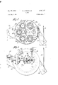
- Figure 2 is a sectional view thereof through the line 2-2 of Figure 1;
- Figure 3 is a top plan view of the filter unit shown in Figure 1;
- Figure 4 is a sectional view through the line 44 of Figure 1 on an exaggerated scale
- Figures 5 and 6 are views similar to Figure 4 showing other positions of the members shown in Figure 4;
- Figure 7 is a fragmentary elevational view of one of the filter elements and its mounting in which brushes are utilized to provide additionally a sweeping or wiping action.
- filter 10 comprises a generally cylindrical housing or body 11 closed at its lower end, as viewed in the drawing, by a collector or bin 12 into which dust or other particles may fall and from which they may be removed.
- a collector or bin 12 Joined to the other end of housing 11 is a cylindrical member 13 with an apertured plate 14 secured between the adjacent portions of housing 11 and cylindrical member 13.
- Cylindrical member 13 is closed at its end remote from housing 11 by a plate-like cover member 15 which, as will be pointed out in detail, serves to support a drive means and control mechanism for actuating a piston-like plunger 16 translatable within cylindrical member 13.
- rotatable plunger housing 17 having an axially extending spindle-like portion 17a of reduced diameter seated in and extending through a hub 18 supported in a central aperture formed in apertured plate 14. Suitable bearings and retainers are provided, as indicated, to secure and facilitate rotation of spindle-like portion 17a.
- Plunger 16 is secured to and translatable with a shaft 19 supported by a bushing 20 mounted in spindle-like portion 17a preferably within the portion thereof encompassed by hub 18 for structural reasons. Adjacent its end remote from plunger 16, shaft 19 carries a collar 21 movement of which in the direction away from plunger 16 is limited by a suitable stop such as nut 22. A coil spring 23 surrounds shaft 19 and extends from collar 21 to a second collar 24 which may abut bushing 20, as shown, or may otherwise be limited in its movement away from collar 21. Thus, when plunger 16 is raised in its housing 17, shaft 13 in its movement therewith serves to compress and load spring 23 between collars 21 and 24.
- Plunger housing 17 is substantially closed except for an opening 25 formed in the bottom thereof through which the area under plunger 16 may communicate with one or more of the filter elements in turn, as will now be described.
- the center of opening 25 is offset from the axis of body 11 by an amount substantially equal to the radius of an annular array of openings 2611-1 formed in plate 14. Openings 26a-f and opening 25 have substantially the same diameter.
- Cages 29 each comprise widely spaced members which extend in generally parallel relation, as shown.
- each of the apertures 26 there is a cage 29 for each of the apertures 26 and each serves to engage and clampingly secure a flange 3dr: formed at one end of a bellows 30. To the other end of bellows 30 there is clamped a perforated or expanded metal filter element support 31 which serves to support filter element 32.
- Bellows 31 may be formed of any suitable material sufiiciently strong and resilient to support the filter element assembly and accumulated dust load and yet normally remain collapsed.
- bellows 30 is constructed of material suitable for high temperature operation, such as asbestos reinforced by helical spring steel wire.
- Flange 3th is formed by suitably molding the asbestos.
- Suitable filter materials vary with the type of installation and. the conditions under which the operation is carried out, as is well known. Matted glass, asbestos fibres, wool felt, as well as other materials, may be utilized. Of course, such material as wool felt may not be utilized successfully where elevated temperatures are encountered.
- the filter element When the filter element is formed of material which is not sufliciently strong to withstand the counterflow, it may be held in place by a wire screen 33 or the like which is also secured by clamps 34. It will be noted that the lower extremities of filter elements 32 are closed as by metal discs 35 which may be part of the supports 31. As will be more fully described, the filter elements may be intermittently forced downward and this downward movement may cause the lower end thereof to strike against the respective cages 29 when an especially violent shake or jolt is desired. In that event, discs 35 receive the full force of the impact rather than the relatively fragile filter material.
- outlet duct 37 may, though not necessarily, open into cylindrical member 13 just below plunger housing 17; the fluid reaching the outlet duct through any of the openings 26 not in registration with opening 25 in plunger housing 17. In some instances, the outlet duct may be dispensed with and cylindrical member 13 may be left open to the atmosphere surrounding it.
- a drive shaft 38 rotatably supported on cover member 15 by bearings 38a, is driven by means of a motor 39 connected thereto through a belt it? and suitable pulleys.
- a gear drive including a pinion 4-1 is connected to drive shaft 33 with pinion 41 extending through cover member 15 to engage a ring gear 64 mounted on end wall 17b of plunger housing 17.
- pinion 41 may engage in holes formed in end wall 17b. in the present instance, with six filter element assemblies mounted in filter it the gear ratio between ring gear 6 and pinion 41 is six to one.
- drive shaft 38 may be rotated relatively slowly and is therefore connected to motor 39 through a suitable speed reduction mechanism. If desired, other sequences and arrangements of the filter elements may be utilized. For example, every other filter element may be brought into registry with opening 25 in which case an odd number of filter elements may be utilized.
- a pulley 42 is rotatably mounted on drive shaft 33 and normally does not rotate with the drive shaft.
- a wire rope or cable 43 is fixed to pulley 42 and to plunger shaft 19 and when pulley 42 rotates with drive shaft rope 43 is wound on pulley 42 thereby raising plunger 16 and compressing spring 23.
- a clutch mechanism is provided to control engagement of pulley 42 with drive shaft 33 and includes a dog 44 rockably mounted on drive shaft 38 and conveniently supported in a slot formed in the end of drive shaft 38 by a pin 52 adjacent to pulley 42.
- Dog 44 has a laterally extending nose portion 45 on one side of its pivot point dimensioned to enter any one of a plurality of holes or recesses 46a-d formed in an array in the side of pulley 42 toward which nose portion 45 is biased by means of a spring 47 engaged between collar 48 fixed to drive shaft 33 and dog 44.
- dog 44 On the other side of its pivot point and extending away from pulley 42, dog 44 carries two spaced apart lugs 59, 50. Dog 44 rotates with drive shaft 38 and lug 49 is positioned on dog 44 so as to engage a pedestal 51 having a cam surface and fixed to cover member 15. As most clearly shown in Figure 4, lug 49 engages the cam surface of pedestal 51 just before it reaches a vertical position and serves to rock. dog 44 about its pivot to carry nose portion 45 away from pulley 42.
- pedestal 51 is positioned adjacent to one side of pulley 42 so as to engage lug 49.
- a bearing block 53 rotatably supports a pivot pin 54 on the side of pedestal 51 away from pulley 42.
- Fixed to the end of pivot pin 54 presented toward pulley 42 is a cam plate 55 while to the opposite end thereof there is fixed a crank arm 56. Lug fit) is positioned on dog 44 so as to clear pedestal 51 as dog 44 rotates with shaft 38 and to engage cam plate 55.
- lug 5b is somewhat longer than lug 49 so.
- crank arm 56 is connected by suitable linkage such as links 57 to one side of a bellows 58 the other side of which is fixed.
- Bellows 58 may communicate directly or, as shown, through a conduit 59 with the interior of inlet duct 36.
- conduit 59 may open into body ill on the upstream side of the filter elements.
- crank arm 56 As bellows 58 expands with increase of pressure, levers 57 serve to rotate crank arm 56 counterclockwise ( Figures 4-6). Conversely, when bellows 53 contracts, crank arm 56 is rotated clockwise.
- Cam plate 55 being connected to crank arm as through pivot pin 54, partakes of this movement of crank arm 56 and its position relative to lug 50 of dog d4 varies, therefore, in accordance with the pressure in inlet duct 3-5 or on the upstream side of the filter elements and, consequently, the pressure differential across filter ill.
- Variations in the porosity of the filter elements serves as a convenient measure of the effectiveness of the filtering operation. Thoroughly clean, fresh filter elements will have maximum porosity and a filtering efiiciency somewhat below that desired. Therefore, when filter unit l d is first put into operation with fresh filter elements, the pressure in inlet duct 36 will be at a correspondingly low level.
- the sensitivity of bellows 53 is adjusted as by varying the tension of calibrating spring as so that it is collapsed and unresponsive to this pressure. Since the eificiency of the filter elements increases with use as its porosity decreases due to trapping of particles within the filter material, there will be an increase in the pressure drop across the filter and a consequent increase in the pressure within inlet duct 36.
- the filter will be performing with substantially maximum efiiciency and this condition is represented by a given range of pressure values upstream and in the inlet duct 36 and by a range of pressure differential magnitudes which may vary somewhat with different filter materials but may be readily determined. For example, with the present installation a pressure differential across the filter corresponding to from 3 to 4 inches of water is suitable.
- a further increase in pressure in the inlet duct 36 above the given pressure range is indicative of a loss in capacity due to choking and blinding of the filter material.
- Bellows 58 is adjusted to respond and expand as the pressure exceeds the desired range with a resultant clockwise rotation of cam plate 55.
- the various parts are in the position occupied thereby when the pressure in inlet duct 36 is below the upper limit of the desired operating pressure range.
- Plunger 16 is in its lowermost position and the tension of coil spring 23 on wire rope 43 maintains the same taut and the rope thereby holds pulley 42 against rotation while drive shaft 38 and dog 44 rotate under the influence of motor 39 which is now energized.
- cam plate 55 When the pressure drop across filter it has increased to just beyond the upper limit of the desired operating range, cam plate 55 reaches the position shown in Figure 6 and lug 54% clears the cam plate with each revolution of drive shaft 38 at a position relative to pulley 42 to permit nose portion 45 of dog 44 to engage in hole 46a. As thus engaged, pulley 42 is rotated about 200, thereby raising plunger it? a corresponding amount and compressing spring 23. At the same time, continued rotation of drive shaft 38 positions opening 25 of plunger housing 17 in registration with one of the openings 26a-f just as lug 49 again engages pedestal 51 to release pulley 42 and to permit spring 23 to urge plunger 16 downward to thereby deliver a relatively mild puff of air to the filter element 32 in registration with, say, opening 26a.
- the Volume of air forced through each of the openings Zeain turn by movement of plunger 16 is sufiiciently large and at such pressure that a counterflow of air takes place through the entire area of each of the filter elements 32 which results in an evenly distributed particle removing action.
- the amount of air delivered when plunger 16 makes its minimum stroke is insufiicient to restore the pressure drop across the filter to desired range under average operating conditions. Thus, when lighter-than-average conditions exist, overcleaning is avoided.
- the relative size of the various parts will, of course, determine the nature of the counterfiow for each position of the dog 4a relative to pulley Q2.
- the force of the counterfiow in any instance will cause expansion of the bellows 3b to produce shaking of the filter element simultaneously with the counterfiow of air therethrough.
- the stroke of the plunger 16 is increased the violence of the shaking action will be correspondingly increased.
- the bellows 3th may be so extended that the discs 35 will strike the bottoms of cages 29 to enhance the shock or particle disturbing action.
- the wide variation in cleaning rate afforded by the structure just described makes practical the maintenance of filter medium density at substantially the optimum level in spite of changing conditions which are so frequently encountered. This is particularly valuable when felted or matted filter mediums, such as wool felt, glass wool batting and the like, are employed.
- 1 may mount a plurality of annular brushes 61 interiorly of each of the cages 29 with the bristles thereof surrounding and engaging the outer surface of filter elements 32 or at least en "cin an excessive accumulation of particles thereon.
- 61 may be spaced apart axially relative to the filter elements a distance corresponding to the axial displacement of filter elements 32 when bellows are each expanded about the average amount for any given installation.
- An advantage of the brushes 61 resides the fact that they will tend to level the accumulated particles on the outer surface or" the filter medium and actually may remove some of the particles thereby preventing the accumulation in certain spots of unduly thick accumulations which might ofier such resistance to the counterfiow and shalting operation as to persist in remaining on the filter me dium, thus reducing its capacity. Also, such spotty accumulations would tend to concentrate the counterilow to those areas devoid of the unusual accumulations and perhaps cause overcleaning of some areas while others remain plugged or blinded by the unusual accumulations.
- arcuate bafiles d2 may be mounted on cages 29 intermediate adjacent filter elements.
- the bafiles may be in tr e form of plate-like members radially disposed in housing 11 intermediate the adjacent filter assemblies.
- housing ll as well as the junctions between it and other members such as apertured plate cylindrical member 23 and inlet duct 36 and elsewhere may readily be rendered substantially gas-tight to avoid leakage of particle-laden fiuid.
- Such connections are well known and need not be described in detail here.
- a filter comprising at least one porous filter element having an upstream and a downstream side, means for leading a particle-laden gas under pressure to the upstream side of said filter element, means adjacent to and communicating with the downstream side of said filter element defining a space having a volume which is large compared to the volume occupied by said filter element, a plunger mounted in said space for movement toward and away from said filter element, and means for rapidly moving said plunger through a distance such that it sweeps a volume which is large compared to that occupied by said filter element and compresses the gas under the same thereby to force gas suddenly to counterfiow substantially simultaneously through all of said filter element against said pressure.
- a filter comprising at least one porous filter element having an upstream and a downstream side, means for leading a particle-laden gas under pressure to the upstream side of said filter element, enclosure means adjacent to and. communicating with the downstream side of said filter element defining a space having a volume which is large compared to the volume occupied by said filter element, a plunger mounted in said space for movement toward and away from said filter element, plunger actuating means for rapidly moving said plunger toward said filter element through a distance such that it sweeps a volume which is large compared to that occupied by said filter element and compresses the gas under the same thereby to force gas suddenly to counter-flow substantially simultaneously through all of said filter element against said pressure, and means including pressure responsive control means for initiating operation of said plunger actuating means and varying the distance traveled by said plunger in accordance with said pressure.
- a filter comprising a generally closed body memher, a plurality of filter elements having upstream and downstream sides and supported in said body member, means for leading a particle-laden gas under pressure into said body member on the upstream side of said filter elements, means for permitting egress of said gas on the downstream side of said filter elements, a housing in said body member and defining a space substantially closed oil from said body member, said space having a volume which is large compared to that of any one of said filter elements, said housing having an aperture formed therethrough, means for successively registering said aperture and at least one of said filter elements whereby said downstream side of said one filter element conmumicates substantially solely with said space, a plunger mounted in said space and movable toward and away "rorn said aperture and any one of said filter elements in registration therewith, and means for rapidly movi.
- said plunger through a distance such that it sweeps a volume which is large compared to that of any one of said filter elements and compresses the gas under the same thereby to force gas suddenly to counterilow substantially simultaneously through all of the filter element in registration with said aperture against said pressure.
- a filter comprising a generally closed body, a plurality of filter elements having upstream and downstream sides and supported in said body, means for leading a particle-laden gas under pressure into said body on the upstream side of said filter elements, means for permitting egress of said gas on the downstream side of said filter elements, a housing in said body and defining a space substantially closed off from said body, said space having a volume which is large compared to that of any one of said filter elements, said housing having an aperture formed therethrough, means for successively registering said aperture and at least one of said filter elements.
- a plunger translatably mounted in said housing and having an effective area large compared to said aperture, and means for translating said plunger in said housing away from said aperture and rapidly toward said aperture through a distance such that the plunger sweeps a volume which is large compared to that of any one of said filter elements and compresses the gas under the same thereby to force gas suddenly to counterfiow substantially simultaneously through all of the filter element in registration with said aperture against said pressure.
- a filter comprising a generally closed body, a plurality of generally tubular filter elements each open at one end thereof and having upstream and downstream sides, means resiliently supporting each of said filter elements in said body in spaced array, inlet means for leading a particle-laden gas under pressure into said body on the upstream side of said filter elements, outlet means for permitting egress of said gas and on the downstream side of said filter elements, a housing in said body and defining a space substantially closed oil from said body, said space having a volume which is large compared to that of any one of said filter elements, said housing having an aperture formed therethroughhaving a size substantially equal to the open end of any one of said filter elements, means for successively registering said aperture and the open ends of said filter elements one by one, a plunger mounted in said space for movement toward and away from said aperture and having an effective area which is large compared to that of said aperture and the open end of any one of said filter elements, and means for rapidly moving said plunger toward said aperture through a distance such that it sweeps a volume which is large
- a filter comprising a generally closed body, a plurality of spaced filter elements having upstream and downstream sides and supported in a circular array in said body, means for leading a particle-laden gas under pressure into said body on the upstream side of said filter elements, outlet means for permitting egress of said gas and on the downstream side of said filter elements, a housing in said body and defining a space substantially closed off from said body, said space having a volume which is large compared to that of any one of said filter elements, said housing having an aperture formed therethrough, means rotatably supporting said housing on said downstream side of said filter elements, drive means, means for engaging said housing with said drive means for rotating said housing and successively registering said aperture with said filter elements, a plunger translatably mounted in said housing 'for movement toward and away from said aperture and having an effective area large compared to said aperture, plunger translating means engaging said plunger for rapidly moving the same through a distance such that it sweeps a volume which is large compared to that of any one of said filter elements, and means for re
- a filter comprising a generally closed body, a plurality of spaced filter elements having upstream and downstream sides and supported in a circular array in said body, means for leading a particle-laden gas under pressure into said body on the upstream side of said filter elements, outlet means for permitting egress of said gas and on the downstream side of said filter elements, a housing in said body and defining a space substantially closed off from said body, said housing having an aperture formed therethrough, means rotatably supporting said housing on said downstream side of said filter elements, drive means, means for engaging said housing with said drive means for rotating said housing and successively registering said aperture with said filter elements, a plunger translatably mounted in said housing for movement toward and away from said aperture and having an elfective area large compared to said aperture, plunger translating means engaging said plunger, clutch means for releasably engaging said drive means with said plunger translating means, and means responsive to the pressure differential across said filter elements for controlling said clutch means, said plunger in its movement toward said aperture causing a counterflow therethrough and substantially
- a filter comprising a generally closed body, a plurality of spaced filter elements having upstream and downstream sides and supported in a circular array in said body, means for leading a particle-laden gas under pressure into said body on the upstream side of said filter elements, outlet means for permitting egress of said gas and on the downstream side of said filter elements, a housing in said body and defining a space substantially closed ofi from said body, said housing having an aperture formed therethrough, means rotatably supporting said housing on said downstream side of said filter elements, drive means, means for engaging said housing with said drive means for rotating said housing and successively registering said aperture with said filter elements,
- a filter comprising a generally closed body, a plurality of spaced filter elements having upstream and downstream sides and supported in a circular array in said body, means for leading a particle-laden gas under pressure into said body on the upstream side of said filter elements, outlet means for permitting egress of said gas and on the downstream side of said filter elements, a housing in said body and defining a space substantially closed off from said body, said housing having an aperture formed therethrough, means rotatably supporting said housing on said downstream side of said filter elements, drive means, means for engaging said housing with said drive means for rotating said housing and successively registering said aperture with said filter elements, a plunger translatably mounted in said housing for movement toward and away from said aperture and having an effective area large compared to said aperture, plunger translating means engaging said plunger, clutch means for releasably engaging said drive means with said plunger translating means which when so engaged serves to move said plunger away from said aperture, and pressureresponsive means connected to said clutch means and responsive to the pressure differential across said filter elements for controlling said clutch means to
- a filter comprising a casing, a plurality of generally tubular filter elements each having an open end, a plurality of resilient expansible tubular bellows members each connected to one of said filter elements adjacent the open end thereof, means supporting said bellows members and the filter elements connected thereto in a cylindric array, inlet means for leading a particle-laden gas under pressure into said body on the upstream side of said filter elements, outlet means for permitting egress of said gas and on the downstream side of said filter elements, partition means defining a space on said downstream side of said filter elements and having an aperture formed therethrough adapted for registration with at least one of said bellows members and the filter elements connected thereto, said space having a volume which is large compared to the volume enclosed by any one of said filter elements, means for successively registering said aperture and said bellows members and thereby putting said space in communication with the interior of said filter elements, a plunger translatably mounted in said space for movement toward and away from said aperture and having an effective area large compared to the cross-
- a filter comprising a casing, a plurality of generally tubular filter elements each having an open end, aplurality of resilient expansible tubular bellows members each connected to one of said filter elements adjacent the open end thereof, means supporting said bellows members and the filter elements connected thereto in a cylindric array, inlet means for leading a particle-laden gas under pressure into said body on the upstream side ofsaid filter elements, outlet means for permitting egress of said gas and on the downstream side of said filter elements, partition means defining a space on said downstream side of said filter elements and having an aperture formed therethrough adapted for registration with at least one of said bellows members and the filter elements connected thereto, drive means, means for engaging said partition means with said drive means for rotating said partition means and successively registering said aperture with each of said bellows members and the filter elements connected thereto whereby said space communicates in succession with the interior of each of said filter elements, a plunger transl'atably mountedin said space for movement toward and away from said aperture and having an effective area
- a filter comprising a casing, a plurality of gen erally tubular filter elements each having an open end, a plurality of resilient expansible tubular bellows members each connected to one of said filter elements adjacent the open end thereof, means supporting said bellows members and the filter elements connected thereto in a cylindrical array, inlet means for leading a particle-laden gas under pressure into said body on the upstream side of said filter elements, outlet means for permitting egress of said gas and on the downstream side of said filter elements, partition means defining a space on saiddownstream side of said filter elements and having an aperture formed therethrough adapted for registration with at least one of said bellows members and the filter elements connected thereto, drive means, means for engaging said partition means with said drive means for rotating said partition means and successively registering said aperture with each-of said bellows members and the filter elements connected thereto whereby said space communicates in succession with the interior of each of said filter elements, a plunger translatably mounted in said space for movement toward and away from said aperture and having an effective area large
Landscapes
- Chemical & Material Sciences (AREA)
- Chemical Kinetics & Catalysis (AREA)
- Filtering Of Dispersed Particles In Gases (AREA)
Description
Jan. 17, W56 H. J. HERSEY, JR
FILTER 3 Sheets-Sheet 2 Filed May 7, 1954 Jan. 17, 1956 H. J. HERSEY, JR
FILTER 5 Sheets-Sheet 3 Filed May 7, 1954 United States PatentO FILTER Henry J. Hersey, Jr., Chatham, N. 1.
Application May 7, 1954, Serial No. 428,243
12 Claims. (Cl. 183-61) My present invention relates to apparatus for removing particles from gases in which they are entrained and more particularly to such apparatus commonly designated as dust filters utilized to remove dust from air to purify the same as well as such apparatus utilized in the recovery or removal of fine particles suspended or entrained in a gaseous atmosphere.
it is known that when a gas laden with solid particles is passed through porous filter material, the particles in time clog the pores of the filter material with a consequent reduction in capacity. As a result, it is necessary in one way or another to recondition the filter material so that the gas may pass through the same at the desired rate. It is also known that where relatively fine particles are being treated there is a serious loss in filter efliciency when new filters or improperly treated filters are utilized. This will be readily understood when it is appreciated that in the case of fine particle sizes the interstices or pores of even the best filter material presently available are large compared thereto and when a new, completely clean filter is put into service the filtration processes are relatively inefiicient at first. As filtration continues, the porosity of the filter material decreases and the desired efficiency is not attained until some appreciable time after the start of the operation.
it is apparent from the foregoing that not only is it costly but also highly inefiicient to replace filter elements Where porosity has become so low as to be objectionable with thoroughly clean or new elements. Thus, numerous efforts have been made to provide means for cleaning or reconditioning the filter elements of a dust filter. The arrangements heretofore provided have included means for cleaning the filter elements in situ and certain refinements have made possible successive cleaning of the filter elements of a multi-element unit without shutting down the filter unit. However, especially where the median particle size of the dust is very small, such arrangements leave much to be desired. 7
One of the problems attending such apparatus is that of maintaining the porosity of the filter elements in a desired range so as to insure uniformity as well as high efiiciency in the operation of the filter unit. Both excessive and insufiicient cleaning result in wide fluctuations in the performance of the unit. Furthermore, variations in conditions such as humidity or the particle load of the gas being treated may require wide variations in the cleaning rate to insure continued optimum operation without shutting down the filter.
It has been found that by periodically causing a reverse flow of gas through the filter element, as by causing a counterflow of air through the entire element, sufficient of the particles which have accumulated to such an extent as to reduce the capacity of the element may be removed so as to reestablish the desired capacity without overcleaning. That is, sufl'lcient particles remain so as to preserve filtering etficiency. By controlling the reverse flow in accordance with the degree to which the porosity of the filter elements has been reduced, bothfiltering 2,731,107 Patented Jan. 17, 1956 lCC capacity and filtering efficiency may be maintained under rather widely varying conditions.
It is therefore a principal object of my invention to provide a self-reconditioning filter unit in which the porosity of the filter elements is automatically maintained at a desired level during long periods of continuous operation.
Another object is to provide such apparatus which is compact and of simple construction.
A further object is to provide such an apparatus in which a counterflow as distinguished from a localized jet of gas or air is forced through all of one or more filter elements of a multiple element filter in a direction counter to that of the gas being filtered.
Yet another object is to provide such apparatus in which a counterflow of gas or air, produced simultaneously through substantially the entirety of one or more filter elements, is automatically controlled by the porosity of the filter elements themselves.
In accordance with my invention I provide means for producing a counterflow through the entirety of one or more filter elements of a filter unit. Furthermore, the intensity and periodicity of the counterflow is automatically controlled by variations in the porosity of the filter elements. Thus, in one embodiment, the filter unit has a plurality of filter elements in the form of tubular members open at one end. A rotatably mounted chamber or cylinder in which a plunger is reciprocable has an opening Which registers in turn with the filter elements at least one by one. Drive means rotate the cylinder while a clutch mechanism serves to couple the plunger to the drive means when and to the degree called for by the pressure drop across the filter elements. Movement of the plunger in one direction serves to load a spring which, when the clutch mechanism releases, serves to forcibly propel the plunger in the opposite direction thereby creating the desired counterflow. The clutch mechanism together with the control means connected thereto determines the degree of travel of the plunger and hence whether and to what extent a counterflow is initiated.
Preferably, the area of the plunger and the volume under or swept out by the plunger are such that even a less than full plunger stroke initiates a counterflow which is both rapid and sudden thereby causing considerable physical agitation of the filter elements in addition to flowing through the pores thereof. To take full advantage of this I may mount the filter elements from resilient bellowslike members which are normally collapsed under the full Weight of the 'filter element and accumulated dust but which expand when the filter elements are struck by the counterflow and contract to agitate additionally the filter elements.
Further objects as well as advantages of my invention will be apparent from the following description thereof in conjunction with the accompanying drawing in which:
Figure 1 is a sectional view through the line 1-1 of Figure 2 of a filter unit constructed inaccordance with my invention;
Figure 2 is a sectional view thereof through the line 2-2 of Figure 1;
Figure 3 is a top plan view of the filter unit shown in Figure 1;
Figure 4 is a sectional view through the line 44 of Figure 1 on an exaggerated scale;
Figures 5 and 6 are views similar to Figure 4 showing other positions of the members shown in Figure 4; and
Figure 7 is a fragmentary elevational view of one of the filter elements and its mounting in which brushes are utilized to provide additionally a sweeping or wiping action.
Referring now to the drawing in detail, filter 10 comprises a generally cylindrical housing or body 11 closed at its lower end, as viewed in the drawing, by a collector or bin 12 into which dust or other particles may fall and from which they may be removed. Joined to the other end of housing 11 is a cylindrical member 13 with an apertured plate 14 secured between the adjacent portions of housing 11 and cylindrical member 13. Cylindrical member 13 is closed at its end remote from housing 11 by a plate-like cover member 15 which, as will be pointed out in detail, serves to support a drive means and control mechanism for actuating a piston-like plunger 16 translatable within cylindrical member 13. Mounted within cylindrical member 13 and enclosing plunger 16 is rotatable plunger housing 17 having an axially extending spindle-like portion 17a of reduced diameter seated in and extending through a hub 18 supported in a central aperture formed in apertured plate 14. Suitable bearings and retainers are provided, as indicated, to secure and facilitate rotation of spindle-like portion 17a.
Plunger 16 is secured to and translatable with a shaft 19 supported by a bushing 20 mounted in spindle-like portion 17a preferably within the portion thereof encompassed by hub 18 for structural reasons. Adjacent its end remote from plunger 16, shaft 19 carries a collar 21 movement of which in the direction away from plunger 16 is limited by a suitable stop such as nut 22. A coil spring 23 surrounds shaft 19 and extends from collar 21 to a second collar 24 which may abut bushing 20, as shown, or may otherwise be limited in its movement away from collar 21. Thus, when plunger 16 is raised in its housing 17, shaft 13 in its movement therewith serves to compress and load spring 23 between collars 21 and 24.
Gas or air laden with particles is led into filter unit 10 through an inlet duct 36 tangentially disposed with respect to body 11 and communicating with the interior thereof. The fluid is under pressure in inlet duct 36 and due to the pressure differential across the filter normally passes through filter elements 32 Where the particles are trapped and passes out through outlet duct 37. As shown, outlet duct 37 may, though not necessarily, open into cylindrical member 13 just below plunger housing 17; the fluid reaching the outlet duct through any of the openings 26 not in registration with opening 25 in plunger housing 17. In some instances, the outlet duct may be dispensed with and cylindrical member 13 may be left open to the atmosphere surrounding it.
The mechanism for initiating and controlling the counterfiow which serves to maintain the filter elements in a substantially ideal condition will now be described in greater detail. A drive shaft 38, rotatably supported on cover member 15 by bearings 38a, is driven by means of a motor 39 connected thereto through a belt it? and suitable pulleys. A gear drive including a pinion 4-1 is connected to drive shaft 33 with pinion 41 extending through cover member 15 to engage a ring gear 64 mounted on end wall 17b of plunger housing 17. Alternatively, pinion 41 may engage in holes formed in end wall 17b. in the present instance, with six filter element assemblies mounted in filter it the gear ratio between ring gear 6 and pinion 41 is six to one. Thus, for every six revolutions of drive shaft 38, plunger housing 17 will complete one traverse or revolution about its axis. Each revolution of drive shaft 38 brings opening 25 into registration with a different one of the openings 26. In practice, drive shaft 38 may be rotated relatively slowly and is therefore connected to motor 39 through a suitable speed reduction mechanism. If desired, other sequences and arrangements of the filter elements may be utilized. For example, every other filter element may be brought into registry with opening 25 in which case an odd number of filter elements may be utilized.
A pulley 42 is rotatably mounted on drive shaft 33 and normally does not rotate with the drive shaft. A wire rope or cable 43 is fixed to pulley 42 and to plunger shaft 19 and when pulley 42 rotates with drive shaft rope 43 is wound on pulley 42 thereby raising plunger 16 and compressing spring 23. A clutch mechanism is provided to control engagement of pulley 42 with drive shaft 33 and includes a dog 44 rockably mounted on drive shaft 38 and conveniently supported in a slot formed in the end of drive shaft 38 by a pin 52 adjacent to pulley 42. Dog 44 has a laterally extending nose portion 45 on one side of its pivot point dimensioned to enter any one of a plurality of holes or recesses 46a-d formed in an array in the side of pulley 42 toward which nose portion 45 is biased by means of a spring 47 engaged between collar 48 fixed to drive shaft 33 and dog 44. On the other side of its pivot point and extending away from pulley 42, dog 44 carries two spaced apart lugs 59, 50. Dog 44 rotates with drive shaft 38 and lug 49 is positioned on dog 44 so as to engage a pedestal 51 having a cam surface and fixed to cover member 15. As most clearly shown in Figure 4, lug 49 engages the cam surface of pedestal 51 just before it reaches a vertical position and serves to rock. dog 44 about its pivot to carry nose portion 45 away from pulley 42.
As shown most clearly in Figures 1 and 3, pedestal 51 is positioned adjacent to one side of pulley 42 so as to engage lug 49. A bearing block 53 rotatably supports a pivot pin 54 on the side of pedestal 51 away from pulley 42. Fixed to the end of pivot pin 54 presented toward pulley 42 is a cam plate 55 while to the opposite end thereof there is fixed a crank arm 56. Lug fit) is positioned on dog 44 so as to clear pedestal 51 as dog 44 rotates with shaft 38 and to engage cam plate 55. As
will be noted, lug 5b is somewhat longer than lug 49 so.
as to extend beyond pedestal 51 and engage cam plate 55 after lug 49 has engaged and been urged inward by pedestal 51 but before lug 49 has cleared pedestal 51. The free end of crank arm 56 is connected by suitable linkage such as links 57 to one side of a bellows 58 the other side of which is fixed. Bellows 58 may communicate directly or, as shown, through a conduit 59 with the interior of inlet duct 36. Alternatively, conduit 59 may open into body ill on the upstream side of the filter elements. Thus, expansion and contraction of bellows 58 is representative of the pressure on the upstream side of the filter elements and consequently displacement of the free side of the bellows varies with this pressure. Normally, variations of this pressure are indicative of variations in the pressure differential across the filter elements. As bellows 58 expands with increase of pressure, levers 57 serve to rotate crank arm 56 counterclockwise (Figures 4-6). Conversely, when bellows 53 contracts, crank arm 56 is rotated clockwise. Cam plate 55, being connected to crank arm as through pivot pin 54, partakes of this movement of crank arm 56 and its position relative to lug 50 of dog d4 varies, therefore, in accordance with the pressure in inlet duct 3-5 or on the upstream side of the filter elements and, consequently, the pressure differential across filter ill. in some installations, where the pressure on the downstream side of the filter elements differs markedly from that of the atmosphere, it may be necessary to enclose bellows 58 and immerse it in an atmosphere at the same pressure obtaining on the downstream side of the filter elements as by leading a conduit therefrom to the bellows enclosure. Alternatively, suitable pressure differential controllers are readily available. Assuming no variation in the condition of filter it the pressure on the upstream side will remain substantially constant since in normal practice the fluid in the inlet duct is led to the filter by a steady, substantially constant pressure source. Thus, when the porosity of the filter elements to the fiuid varies in use, the pressure on the upstream side or the pressure differential across the filter wil vary accordingly.v
Variations in the porosity of the filter elements serves as a convenient measure of the effectiveness of the filtering operation. Thoroughly clean, fresh filter elements will have maximum porosity and a filtering efiiciency somewhat below that desired. Therefore, when filter unit l d is first put into operation with fresh filter elements, the pressure in inlet duct 36 will be at a correspondingly low level. The sensitivity of bellows 53 is adjusted as by varying the tension of calibrating spring as so that it is collapsed and unresponsive to this pressure. Since the eificiency of the filter elements increases with use as its porosity decreases due to trapping of particles within the filter material, there will be an increase in the pressure drop across the filter and a consequent increase in the pressure within inlet duct 36. As the operation continues, the filter will be performing with substantially maximum efiiciency and this condition is represented by a given range of pressure values upstream and in the inlet duct 36 and by a range of pressure differential magnitudes which may vary somewhat with different filter materials but may be readily determined. For example, with the present installation a pressure differential across the filter corresponding to from 3 to 4 inches of water is suitable.
A further increase in pressure in the inlet duct 36 above the given pressure range is indicative ofa loss in capacity due to choking and blinding of the filter material. Bellows 58 is adjusted to respond and expand as the pressure exceeds the desired range with a resultant clockwise rotation of cam plate 55. As shown in Figure 5, the various parts are in the position occupied thereby when the pressure in inlet duct 36 is below the upper limit of the desired operating pressure range. Plunger 16 is in its lowermost position and the tension of coil spring 23 on wire rope 43 maintains the same taut and the rope thereby holds pulley 42 against rotation while drive shaft 38 and dog 44 rotate under the influence of motor 39 which is now energized. Even when lug 49 has cleared pedestal 51, nose portion is held out of engagement wtih holes 46 by reason of lug being engaged by cam plate as nose portion 45 traverses that portion of pulley 42 in which holes 46ad are located. It is to be noted that as lug 50 clears cam plate 55, nose portion 45 in its corresponding position has progressed beyond the point at which it can enter the last of the holes 46a-d and it therefore slides along the smooth side surface of pulley 44 until lug 49 once again engages pedestal 51.
When the pressure drop across filter it has increased to just beyond the upper limit of the desired operating range, cam plate 55 reaches the position shown in Figure 6 and lug 54% clears the cam plate with each revolution of drive shaft 38 at a position relative to pulley 42 to permit nose portion 45 of dog 44 to engage in hole 46a. As thus engaged, pulley 42 is rotated about 200, thereby raising plunger it? a corresponding amount and compressing spring 23. At the same time, continued rotation of drive shaft 38 positions opening 25 of plunger housing 17 in registration with one of the openings 26a-f just as lug 49 again engages pedestal 51 to release pulley 42 and to permit spring 23 to urge plunger 16 downward to thereby deliver a relatively mild puff of air to the filter element 32 in registration with, say, opening 26a. The next revolution of drive shaft 38 serves to rotate plunger housing 17 just enough to position its opening 5 in registration with the opening 26 During this revolution of the drive shaft, pulley 42 is again engaged and rotates about 290 to rewind rope 43 and raise plunger 16. Release of pulley 42 new results in delivery of air to the filter element under opening 26).
As has been pointed out, the Volume of air forced through each of the openings Zeain turn by movement of plunger 16 is sufiiciently large and at such pressure that a counterflow of air takes place through the entire area of each of the filter elements 32 which results in an evenly distributed particle removing action. Preferably, for any particular installation the amount of air delivered when plunger 16 makes its minimum stroke is insufiicient to restore the pressure drop across the filter to desired range under average operating conditions. Thus, when lighter-than-average conditions exist, overcleaning is avoided.
Under average or heavier-than-average conditions there will be a continued increase in the pressure drop across filter unit it This would indicate that the limited stroke of plunger 16 corresponding to engagement of dog 44 in pulley hole 46:: has been insufficient to keep pace with the continuing decrease in capacity of the filter. Consequently, bellows 58 will continue to expand and thereby rotate cam plate 55 counterclockwise to permit dog 44 to engage pulley holes 46b, 0 or d and thereby increase the stroke of plunger to. When dog d4 engages hole 46d, pulley 42 is wound about 315, as shown in Figure 4; cam plate 55 now being positioned so that lug 5b does not come into engagement therewith and plunger 16 being raised to its full height before being released.
The relative size of the various parts will, of course, determine the nature of the counterfiow for each position of the dog 4a relative to pulley Q2. The force of the counterfiow in any instance will cause expansion of the bellows 3b to produce shaking of the filter element simultaneously with the counterfiow of air therethrough. As the stroke of the plunger 16 is increased the violence of the shaking action will be correspondingly increased. When conditions are such that the plunger approaches its maximum stroke, the bellows 3th may be so extended that the discs 35 will strike the bottoms of cages 29 to enhance the shock or particle disturbing action. The wide variation in cleaning rate afforded by the structure just described makes practical the maintenance of filter medium density at substantially the optimum level in spite of changing conditions which are so frequently encountered. This is particularly valuable when felted or matted filter mediums, such as wool felt, glass wool batting and the like, are employed.
As shown in Figure 7, 1 may mount a plurality of annular brushes 61 interiorly of each of the cages 29 with the bristles thereof surrounding and engaging the outer surface of filter elements 32 or at least en "cin an excessive accumulation of particles thereon. 61 may be spaced apart axially relative to the filter elements a distance corresponding to the axial displacement of filter elements 32 when bellows are each expanded about the average amount for any given installation. An advantage of the brushes 61 resides the fact that they will tend to level the accumulated particles on the outer surface or" the filter medium and actually may remove some of the particles thereby preventing the accumulation in certain spots of unduly thick accumulations which might ofier such resistance to the counterfiow and shalting operation as to persist in remaining on the filter me dium, thus reducing its capacity. Also, such spotty accumulations would tend to concentrate the counterilow to those areas devoid of the unusual accumulations and perhaps cause overcleaning of some areas while others remain plugged or blinded by the unusual accumulations.
To avoid the immediate redeposit of particles removed from one filter element 32 unto an adjacent filter element, arcuate bafiles d2 may be mounted on cages 29 intermediate adjacent filter elements. Alternatively, the bafiles may be in tr e form of plate-like members radially disposed in housing 11 intermediate the adjacent filter assemblies.
it is to be understood that housing ll as well as the junctions between it and other members such as apertured plate cylindrical member 23 and inlet duct 36 and elsewhere may readily be rendered substantially gas-tight to avoid leakage of particle-laden fiuid. Such connections are well known and need not be described in detail here.
The terms and expressions which i have employed are used as terms of description and not of limitation, and l have no intention, in the use of such terms and expressions, of excluding any equivalents of the features shown and described or portions thereof, but recognize that various modifications are possible within the scope of the invention claimed.
What is claimed is:
1. A filter, comprising at least one porous filter element having an upstream and a downstream side, means for leading a particle-laden gas under pressure to the upstream side of said filter element, means adjacent to and communicating with the downstream side of said filter element defining a space having a volume which is large compared to the volume occupied by said filter element, a plunger mounted in said space for movement toward and away from said filter element, and means for rapidly moving said plunger through a distance such that it sweeps a volume which is large compared to that occupied by said filter element and compresses the gas under the same thereby to force gas suddenly to counterfiow substantially simultaneously through all of said filter element against said pressure.
2. A filter, comprising at least one porous filter element having an upstream and a downstream side, means for leading a particle-laden gas under pressure to the upstream side of said filter element, enclosure means adjacent to and. communicating with the downstream side of said filter element defining a space having a volume which is large compared to the volume occupied by said filter element, a plunger mounted in said space for movement toward and away from said filter element, plunger actuating means for rapidly moving said plunger toward said filter element through a distance such that it sweeps a volume which is large compared to that occupied by said filter element and compresses the gas under the same thereby to force gas suddenly to counter-flow substantially simultaneously through all of said filter element against said pressure, and means including pressure responsive control means for initiating operation of said plunger actuating means and varying the distance traveled by said plunger in accordance with said pressure.
3. A filter, comprising a generally closed body memher, a plurality of filter elements having upstream and downstream sides and supported in said body member, means for leading a particle-laden gas under pressure into said body member on the upstream side of said filter elements, means for permitting egress of said gas on the downstream side of said filter elements, a housing in said body member and defining a space substantially closed oil from said body member, said space having a volume which is large compared to that of any one of said filter elements, said housing having an aperture formed therethrough, means for successively registering said aperture and at least one of said filter elements whereby said downstream side of said one filter element conmumicates substantially solely with said space, a plunger mounted in said space and movable toward and away "rorn said aperture and any one of said filter elements in registration therewith, and means for rapidly movi. g said plunger through a distance such that it sweeps a volume which is large compared to that of any one of said filter elements and compresses the gas under the same thereby to force gas suddenly to counterilow substantially simultaneously through all of the filter element in registration with said aperture against said pressure.
4. A filter, comprising a generally closed body, a plurality of filter elements having upstream and downstream sides and supported in said body, means for leading a particle-laden gas under pressure into said body on the upstream side of said filter elements, means for permitting egress of said gas on the downstream side of said filter elements, a housing in said body and defining a space substantially closed off from said body, said space having a volume which is large compared to that of any one of said filter elements, said housing having an aperture formed therethrough, means for successively registering said aperture and at least one of said filter elements. a plunger translatably mounted in said housing and having an effective area large compared to said aperture, and means for translating said plunger in said housing away from said aperture and rapidly toward said aperture through a distance such that the plunger sweeps a volume which is large compared to that of any one of said filter elements and compresses the gas under the same thereby to force gas suddenly to counterfiow substantially simultaneously through all of the filter element in registration with said aperture against said pressure.
5. A filter, comprising a generally closed body, a plurality of generally tubular filter elements each open at one end thereof and having upstream and downstream sides, means resiliently supporting each of said filter elements in said body in spaced array, inlet means for leading a particle-laden gas under pressure into said body on the upstream side of said filter elements, outlet means for permitting egress of said gas and on the downstream side of said filter elements, a housing in said body and defining a space substantially closed oil from said body, said space having a volume which is large compared to that of any one of said filter elements, said housing having an aperture formed therethroughhaving a size substantially equal to the open end of any one of said filter elements, means for successively registering said aperture and the open ends of said filter elements one by one, a plunger mounted in said space for movement toward and away from said aperture and having an effective area which is large compared to that of said aperture and the open end of any one of said filter elements, and means for rapidly moving said plunger toward said aperture through a distance such that it sweeps a volume which is large compared to that of, any one of said filter elements and compresses the gas under the same thereby to force gas suddenly to counterflow substantially simultaneously through all of the filter element in registration with said aperture against said pressure.
6. A filter, comprising a generally closed body, a plurality of spaced filter elements having upstream and downstream sides and supported in a circular array in said body, means for leading a particle-laden gas under pressure into said body on the upstream side of said filter elements, outlet means for permitting egress of said gas and on the downstream side of said filter elements, a housing in said body and defining a space substantially closed off from said body, said space having a volume which is large compared to that of any one of said filter elements, said housing having an aperture formed therethrough, means rotatably supporting said housing on said downstream side of said filter elements, drive means, means for engaging said housing with said drive means for rotating said housing and successively registering said aperture with said filter elements, a plunger translatably mounted in said housing 'for movement toward and away from said aperture and having an effective area large compared to said aperture, plunger translating means engaging said plunger for rapidly moving the same through a distance such that it sweeps a volume which is large compared to that of any one of said filter elements, and means for releasably engaging said drive means with said plunger translating means, said plunger in its movement toward said aperture causing a counterflow therethrough and substantially simultaneously through the entire surface of said filter elements when in registration with said aperture and against said pressure.
7. A filter, comprising a generally closed body, a plurality of spaced filter elements having upstream and downstream sides and supported in a circular array in said body, means for leading a particle-laden gas under pressure into said body on the upstream side of said filter elements, outlet means for permitting egress of said gas and on the downstream side of said filter elements, a housing in said body and defining a space substantially closed off from said body, said housing having an aperture formed therethrough, means rotatably supporting said housing on said downstream side of said filter elements, drive means, means for engaging said housing with said drive means for rotating said housing and successively registering said aperture with said filter elements, a plunger translatably mounted in said housing for movement toward and away from said aperture and having an elfective area large compared to said aperture, plunger translating means engaging said plunger, clutch means for releasably engaging said drive means with said plunger translating means, and means responsive to the pressure differential across said filter elements for controlling said clutch means, said plunger in its movement toward said aperture causing a counterflow therethrough and substantially simultaneously through the entire surface of said filter elements when in registration with said aperture and against said pressure.
8. A filter, comprising a generally closed body, a plurality of spaced filter elements having upstream and downstream sides and supported in a circular array in said body, means for leading a particle-laden gas under pressure into said body on the upstream side of said filter elements, outlet means for permitting egress of said gas and on the downstream side of said filter elements, a housing in said body and defining a space substantially closed ofi from said body, said housing having an aperture formed therethrough, means rotatably supporting said housing on said downstream side of said filter elements, drive means, means for engaging said housing with said drive means for rotating said housing and successively registering said aperture with said filter elements,
a plunger translatably mounted in said housing for movement toward and away from said aperture and having an effective area large compared to said aperture, plunger translating means engaging said plunger, clutch means for releasably engaging said drive means with said plunger translating means which when so engaged serves to move said plunger away from said aperture, and means responsive to the pressure differential across said filter elements and for controlling said clutch means to thereby determine the movement of said plunger away from said aperture, said plunger in its movement toward said aperture causing a counterflow therethrough and substantially simultaneously through the entire surface of said filter elements when in registration with said aperture and against said pressure.
9. A filter, comprising a generally closed body, a plurality of spaced filter elements having upstream and downstream sides and supported in a circular array in said body, means for leading a particle-laden gas under pressure into said body on the upstream side of said filter elements, outlet means for permitting egress of said gas and on the downstream side of said filter elements, a housing in said body and defining a space substantially closed off from said body, said housing having an aperture formed therethrough, means rotatably supporting said housing on said downstream side of said filter elements, drive means, means for engaging said housing with said drive means for rotating said housing and successively registering said aperture with said filter elements, a plunger translatably mounted in said housing for movement toward and away from said aperture and having an effective area large compared to said aperture, plunger translating means engaging said plunger, clutch means for releasably engaging said drive means with said plunger translating means which when so engaged serves to move said plunger away from said aperture, and pressureresponsive means connected to said clutch means and responsive to the pressure differential across said filter elements for controlling said clutch means to thereby control the movement of said plunger away from said aperture, said plunger in its movement toward said aperture causing a counterflow therethrough and substantially simultaneously through the entire surface of said filter elements when in registration with said aperture and against said pressure.
10. A filter, comprising a casing, a plurality of generally tubular filter elements each having an open end, a plurality of resilient expansible tubular bellows members each connected to one of said filter elements adjacent the open end thereof, means supporting said bellows members and the filter elements connected thereto in a cylindric array, inlet means for leading a particle-laden gas under pressure into said body on the upstream side of said filter elements, outlet means for permitting egress of said gas and on the downstream side of said filter elements, partition means defining a space on said downstream side of said filter elements and having an aperture formed therethrough adapted for registration with at least one of said bellows members and the filter elements connected thereto, said space having a volume which is large compared to the volume enclosed by any one of said filter elements, means for successively registering said aperture and said bellows members and thereby putting said space in communication with the interior of said filter elements, a plunger translatably mounted in said space for movement toward and away from said aperture and having an effective area large compared to the cross-sectional area of any one of said filter elements, and means for translating said plunger in said space away from said aperture and rapidly toward said aperture through a distance such that the plunger sweeps a volume which is large compared to that enclosed by any one of said filter elements for causing a counterflow of gas substantially simultaneously through the entire surface of the filter element in registration with said aperture against said pressure.
11. A filter, comprising a casing, a plurality of generally tubular filter elements each having an open end, aplurality of resilient expansible tubular bellows members each connected to one of said filter elements adjacent the open end thereof, means supporting said bellows members and the filter elements connected thereto in a cylindric array, inlet means for leading a particle-laden gas under pressure into said body on the upstream side ofsaid filter elements, outlet means for permitting egress of said gas and on the downstream side of said filter elements, partition means defining a space on said downstream side of said filter elements and having an aperture formed therethrough adapted for registration with at least one of said bellows members and the filter elements connected thereto, drive means, means for engaging said partition means with said drive means for rotating said partition means and successively registering said aperture with each of said bellows members and the filter elements connected thereto whereby said space communicates in succession with the interior of each of said filter elements, a plunger transl'atably mountedin said space for movement toward and away from said aperture and having an effective area large compared to the area of any one of said filter elements, plunger translating means engaging said plunger, clutch means for releasably engaging said drive means with said plunger translating means which when so engaged serves to move said plunger away from said aperture, and means responsive to the pressure dilferential across said filter elements and connected to said clutch means for controlling the same and thereby controlling the movement of said plunger away from said aperture, said plunger in its movement toward said aperture causing a counterfiow therethrough and substantially simultaneously through the entire surface of said filter elements when in registration with said aperture and against said pressure, said counterfiow causing said bellows members connected to the filter elements receiving said counterfiow to expand and move the filter elements connected thereto.
12. A filter, comprising a casing, a plurality of gen erally tubular filter elements each having an open end, a plurality of resilient expansible tubular bellows members each connected to one of said filter elements adjacent the open end thereof, means supporting said bellows members and the filter elements connected thereto in a cylindrical array, inlet means for leading a particle-laden gas under pressure into said body on the upstream side of said filter elements, outlet means for permitting egress of said gas and on the downstream side of said filter elements, partition means defining a space on saiddownstream side of said filter elements and having an aperture formed therethrough adapted for registration with at least one of said bellows members and the filter elements connected thereto, drive means, means for engaging said partition means with said drive means for rotating said partition means and successively registering said aperture with each-of said bellows members and the filter elements connected thereto whereby said space communicates in succession with the interior of each of said filter elements, a plunger translatably mounted in said space for movement toward and away from said aperture and having an effective area large compared to the area of any one of said filter elements, plungertranslating means engaging said plunger, clutch means for releasably engaging said drive means with said plunger translating means which when so engaged serves to move said plunger away from said aperture and when released serves to rapidly move said plunger toward said aperture, means responsive to the pressure differential across said filter elements and connected to said clutch means for controlling the same and thereby controlling the movement of said plunger away from said aperture, said plunger in its movement toward said aperture causing a counterfiow therethrough and through substantially simultaneously the entire surface of said filter elements when in registration with said aperture and against said pressure, and a plurality of spaced brushes contacting the outer surface of each of said filter elements, said bellows members expanding when the filter elements connected thereto receive said counterflow and thereby moving said filter elements relative to said brushes.
References Cited in the file of this patent UNITED STATES PATENTS 996,519 Peter June 27, 1911 1,516,444 Lough Nov. 18, 1924 2,391,534 Yerrick et al Dec. 25, 1945 FOREIGN PATENTS 9,390 Great Britain June 26, 1915 368,731 Great Britain Mar. 1, 1932 521,165 Germany Mar, 18, 1931 700,782 Great Britain Dec. 9, 1953 875,908 Germany May 7, 1.953 1,040,053 France May 21, 1953
Priority Applications (3)
| Application Number | Priority Date | Filing Date | Title |
|---|---|---|---|
| US428243A US2731107A (en) | 1954-05-07 | 1954-05-07 | Filter |
| GB12132/55A GB768918A (en) | 1954-05-07 | 1955-04-27 | Improvements in or relating to gas filters |
| FR1130258D FR1130258A (en) | 1954-05-07 | 1955-05-06 | Improvements to a filter |
Applications Claiming Priority (1)
| Application Number | Priority Date | Filing Date | Title |
|---|---|---|---|
| US428243A US2731107A (en) | 1954-05-07 | 1954-05-07 | Filter |
Publications (1)
| Publication Number | Publication Date |
|---|---|
| US2731107A true US2731107A (en) | 1956-01-17 |
Family
ID=23698081
Family Applications (1)
| Application Number | Title | Priority Date | Filing Date |
|---|---|---|---|
| US428243A Expired - Lifetime US2731107A (en) | 1954-05-07 | 1954-05-07 | Filter |
Country Status (3)
| Country | Link |
|---|---|
| US (1) | US2731107A (en) |
| FR (1) | FR1130258A (en) |
| GB (1) | GB768918A (en) |
Cited By (31)
| Publication number | Priority date | Publication date | Assignee | Title |
|---|---|---|---|---|
| US2796950A (en) * | 1955-04-11 | 1957-06-25 | Jr Henry Johnson Hersey | Filter |
| US2844216A (en) * | 1956-04-02 | 1958-07-22 | Day Company | Air filtering apparatus |
| US2887176A (en) * | 1956-12-06 | 1959-05-19 | Apra Precipitator Corp | Purge means for rectangular precipitator |
| US2911060A (en) * | 1957-10-16 | 1959-11-03 | Apra Precipitator Corp | Horizontal plane purge for precipitator |
| US2976953A (en) * | 1958-05-16 | 1961-03-28 | Koppers Co Inc | Filter |
| US3080694A (en) * | 1959-06-22 | 1963-03-12 | Lofton H Smith | Air filter |
| US3176846A (en) * | 1961-10-17 | 1965-04-06 | Renard P Adams | Automatic strainer |
| US3271936A (en) * | 1963-01-30 | 1966-09-13 | Ventola Sa Atel Const | Apparatus for collecting automatically fibrous materials suspended in air |
| US3280980A (en) * | 1966-01-03 | 1966-10-25 | William R King | Self-cleaning filter |
| DE1228130B (en) * | 1956-07-09 | 1966-11-03 | Slick Ind Company | Process for cleaning hollow filter elements from dust collectors by pressure surge backwashing using scavenging air and pressurized gas backwashing device |
| US3356215A (en) * | 1965-04-22 | 1967-12-05 | Dorr Oliver Inc | Apparatus and method for the filtration-thickening of suspensions of solids |
| US3365065A (en) * | 1965-04-16 | 1968-01-23 | Varjabedian Jack | Filter with liquid displacing piston |
| US3813853A (en) * | 1971-08-30 | 1974-06-04 | Andersons | Dust filter |
| US4306890A (en) * | 1979-10-17 | 1981-12-22 | Bahco Industri Ab | Apparatus for cleaning of filter elements |
| US4642188A (en) * | 1985-05-29 | 1987-02-10 | Dover Corporation | Backwash apparatus for multi element filter unit |
| US4865627A (en) * | 1987-10-30 | 1989-09-12 | Shell Oil Company | Method and apparatus for separating fine particulates from a mixture of fine particulates and gas |
| US5616171A (en) * | 1994-01-07 | 1997-04-01 | Donaldson Company, Inc. | Pulse jet filter cleaning system |
| US5792373A (en) * | 1996-05-31 | 1998-08-11 | Delaware Capital Formation, Inc. | Backwash filter system |
| WO2001066222A1 (en) * | 2000-03-04 | 2001-09-13 | Boll & Kirch Filterbau Gmbh | Elutriation filter |
| EP1254690A3 (en) * | 2001-05-04 | 2003-03-05 | H. William Morgan, Jr. | Liquid filtration device with backwashing feature |
| US6576146B2 (en) | 2001-10-05 | 2003-06-10 | Nmw, Incorporated | Filtration element employing improved backwash feature and method of utilizing same |
| WO2011003490A1 (en) * | 2009-07-07 | 2011-01-13 | Khs Gmbh | Precoat filter and filtering elements for use in a filter of this type |
| CN105381636A (en) * | 2015-12-15 | 2016-03-09 | 中核第四研究设计工程有限公司 | Full-automatic self-cleaning filter |
| EP2704811B1 (en) * | 2011-05-05 | 2017-11-08 | Hydac Process Technology GmbH | Filtering apparatus |
| US20210039023A1 (en) * | 2018-03-23 | 2021-02-11 | Blue Skies Global LLC | Regenerative media filtration |
| US20210245078A1 (en) * | 2018-06-13 | 2021-08-12 | Cargill, Incorporated | Liquid discharge filter and its use |
| US20210346824A1 (en) * | 2020-04-13 | 2021-11-11 | Evoqua Water Techhnologies LLC | Regenerative Media Filtration Apparatus Improvements |
| CN114772915A (en) * | 2022-05-05 | 2022-07-22 | 赋腾河北节能科技有限责任公司 | Air duct system of energy-saving glass tempering unit |
| CN115006940A (en) * | 2022-06-08 | 2022-09-06 | 山东省地质矿产勘查开发局八〇一水文地质工程地质大队(山东省地矿工程勘察院) | A new type of urban ecological environment protection device |
| US20230001335A1 (en) * | 2015-09-10 | 2023-01-05 | 1934612 Ontario Inc. | Methods and systems for dewatering solid particles in a contaminated liquid mixture |
| US20240318514A1 (en) * | 2023-03-21 | 2024-09-26 | Saudi Arabian Oil Company | Systems and methods for operating candle filters to recover glycols from drilling operations |
Families Citing this family (8)
| Publication number | Priority date | Publication date | Assignee | Title |
|---|---|---|---|---|
| US4231770A (en) * | 1979-09-18 | 1980-11-04 | Johnson Jr Allen S | Bag-type filter apparatus with internal air diffuser |
| DE19734588A1 (en) * | 1997-08-09 | 1999-02-11 | Boll & Kirch Filter | Backwashing filter |
| CN107754489B (en) * | 2017-12-14 | 2018-09-07 | 王柱盛 | A kind of energy conservation and environmental protection dust high-efficient treatment device |
| CN109647069B (en) * | 2019-01-31 | 2021-04-27 | 蔡德秀 | Self-cleaning dust filtering device for filter screen |
| CN109772009B (en) * | 2019-03-08 | 2021-01-29 | 苏州吉态来胺生物科技有限公司 | Chemical industry is with crossing jar |
| CN111921288A (en) * | 2020-08-28 | 2020-11-13 | 戴旭凡 | Pulse bag type dust collector |
| CN113198281B (en) * | 2021-05-08 | 2022-12-09 | 威克特(山东)生物科技有限公司 | Environment-friendly air purification treatment device and treatment method |
| CN114259802B (en) * | 2021-11-22 | 2022-12-20 | 江苏东方滤袋股份有限公司 | High-efficient dust removal filter bag with dust collecting function |
Citations (9)
| Publication number | Priority date | Publication date | Assignee | Title |
|---|---|---|---|---|
| US996519A (en) * | 1909-09-02 | 1911-06-27 | Jacob Peter | Multitubular dust-collector. |
| GB191509390A (en) * | 1915-06-26 | 1915-11-04 | Sturtevant Eng Co Ltd | Improvements in and connected with Air Filters. |
| US1516444A (en) * | 1921-05-10 | 1924-11-18 | Gerald A Lough | Drying apparatus and process |
| DE521165C (en) * | 1931-03-18 | Steitz & Co G M B H | Control device for bag filter | |
| GB368731A (en) * | 1930-12-01 | 1932-03-01 | Gen Electric Co Ltd | Improvements in or relating to gas filtering apparatus |
| US2391534A (en) * | 1944-06-02 | 1945-12-25 | Air Preheater | Separator |
| DE875908C (en) * | 1948-10-02 | 1953-05-07 | Intensiv Filter Gmbh | Bag filter |
| FR1040053A (en) * | 1951-07-24 | 1953-10-13 | Device for obtaining mechanical degumming of air filters | |
| GB700782A (en) * | 1951-05-21 | 1953-12-09 | Prep Ind Combustibles | Improvements in or relating to gas-filtering devices |
-
1954
- 1954-05-07 US US428243A patent/US2731107A/en not_active Expired - Lifetime
-
1955
- 1955-04-27 GB GB12132/55A patent/GB768918A/en not_active Expired
- 1955-05-06 FR FR1130258D patent/FR1130258A/en not_active Expired
Patent Citations (9)
| Publication number | Priority date | Publication date | Assignee | Title |
|---|---|---|---|---|
| DE521165C (en) * | 1931-03-18 | Steitz & Co G M B H | Control device for bag filter | |
| US996519A (en) * | 1909-09-02 | 1911-06-27 | Jacob Peter | Multitubular dust-collector. |
| GB191509390A (en) * | 1915-06-26 | 1915-11-04 | Sturtevant Eng Co Ltd | Improvements in and connected with Air Filters. |
| US1516444A (en) * | 1921-05-10 | 1924-11-18 | Gerald A Lough | Drying apparatus and process |
| GB368731A (en) * | 1930-12-01 | 1932-03-01 | Gen Electric Co Ltd | Improvements in or relating to gas filtering apparatus |
| US2391534A (en) * | 1944-06-02 | 1945-12-25 | Air Preheater | Separator |
| DE875908C (en) * | 1948-10-02 | 1953-05-07 | Intensiv Filter Gmbh | Bag filter |
| GB700782A (en) * | 1951-05-21 | 1953-12-09 | Prep Ind Combustibles | Improvements in or relating to gas-filtering devices |
| FR1040053A (en) * | 1951-07-24 | 1953-10-13 | Device for obtaining mechanical degumming of air filters |
Cited By (42)
| Publication number | Priority date | Publication date | Assignee | Title |
|---|---|---|---|---|
| US2796950A (en) * | 1955-04-11 | 1957-06-25 | Jr Henry Johnson Hersey | Filter |
| US2844216A (en) * | 1956-04-02 | 1958-07-22 | Day Company | Air filtering apparatus |
| DE1228130B (en) * | 1956-07-09 | 1966-11-03 | Slick Ind Company | Process for cleaning hollow filter elements from dust collectors by pressure surge backwashing using scavenging air and pressurized gas backwashing device |
| US2887176A (en) * | 1956-12-06 | 1959-05-19 | Apra Precipitator Corp | Purge means for rectangular precipitator |
| US2911060A (en) * | 1957-10-16 | 1959-11-03 | Apra Precipitator Corp | Horizontal plane purge for precipitator |
| US2976953A (en) * | 1958-05-16 | 1961-03-28 | Koppers Co Inc | Filter |
| US3080694A (en) * | 1959-06-22 | 1963-03-12 | Lofton H Smith | Air filter |
| US3176846A (en) * | 1961-10-17 | 1965-04-06 | Renard P Adams | Automatic strainer |
| US3271936A (en) * | 1963-01-30 | 1966-09-13 | Ventola Sa Atel Const | Apparatus for collecting automatically fibrous materials suspended in air |
| US3365065A (en) * | 1965-04-16 | 1968-01-23 | Varjabedian Jack | Filter with liquid displacing piston |
| US3356215A (en) * | 1965-04-22 | 1967-12-05 | Dorr Oliver Inc | Apparatus and method for the filtration-thickening of suspensions of solids |
| US3280980A (en) * | 1966-01-03 | 1966-10-25 | William R King | Self-cleaning filter |
| US3813853A (en) * | 1971-08-30 | 1974-06-04 | Andersons | Dust filter |
| US4306890A (en) * | 1979-10-17 | 1981-12-22 | Bahco Industri Ab | Apparatus for cleaning of filter elements |
| US4642188A (en) * | 1985-05-29 | 1987-02-10 | Dover Corporation | Backwash apparatus for multi element filter unit |
| US4865627A (en) * | 1987-10-30 | 1989-09-12 | Shell Oil Company | Method and apparatus for separating fine particulates from a mixture of fine particulates and gas |
| US5616171A (en) * | 1994-01-07 | 1997-04-01 | Donaldson Company, Inc. | Pulse jet filter cleaning system |
| US5792373A (en) * | 1996-05-31 | 1998-08-11 | Delaware Capital Formation, Inc. | Backwash filter system |
| US20020158002A1 (en) * | 2000-03-04 | 2002-10-31 | Birgit Trotzki | Elutriation filter |
| WO2001066222A1 (en) * | 2000-03-04 | 2001-09-13 | Boll & Kirch Filterbau Gmbh | Elutriation filter |
| US6872310B2 (en) * | 2000-03-04 | 2005-03-29 | Boll & Kirch Filderbzu Gmbh | Precoated filter for the filtration of flowing media |
| US20020038783A1 (en) * | 2000-03-04 | 2002-04-04 | Birgit Trotzki | Precoated filter for the filtration of flowing media |
| EP1254690A3 (en) * | 2001-05-04 | 2003-03-05 | H. William Morgan, Jr. | Liquid filtration device with backwashing feature |
| US6576146B2 (en) | 2001-10-05 | 2003-06-10 | Nmw, Incorporated | Filtration element employing improved backwash feature and method of utilizing same |
| WO2011003490A1 (en) * | 2009-07-07 | 2011-01-13 | Khs Gmbh | Precoat filter and filtering elements for use in a filter of this type |
| US20120061303A1 (en) * | 2009-07-07 | 2012-03-15 | Khs Gmbh | Precoat filter and filtering elements for use in a filter of this type |
| EP2704811B1 (en) * | 2011-05-05 | 2017-11-08 | Hydac Process Technology GmbH | Filtering apparatus |
| US20230001335A1 (en) * | 2015-09-10 | 2023-01-05 | 1934612 Ontario Inc. | Methods and systems for dewatering solid particles in a contaminated liquid mixture |
| US12083453B2 (en) * | 2015-09-10 | 2024-09-10 | 1934612 Ontario Inc. | Methods and systems for dewatering solid particles in a contaminated liquid mixture |
| CN105381636A (en) * | 2015-12-15 | 2016-03-09 | 中核第四研究设计工程有限公司 | Full-automatic self-cleaning filter |
| US20210039023A1 (en) * | 2018-03-23 | 2021-02-11 | Blue Skies Global LLC | Regenerative media filtration |
| US20210229006A1 (en) * | 2018-03-23 | 2021-07-29 | Blue Skies Global LLC | Regenerative media filtration |
| US12330093B2 (en) * | 2018-03-23 | 2025-06-17 | Blue Skies Global LLC | Regenerative media filtration |
| US12330094B2 (en) * | 2018-03-23 | 2025-06-17 | Blue Skies Global LLC | Regenerative media filtration |
| US20210245078A1 (en) * | 2018-06-13 | 2021-08-12 | Cargill, Incorporated | Liquid discharge filter and its use |
| US11717775B2 (en) * | 2018-06-13 | 2023-08-08 | Cargill, Incorporated | Liquid discharge filter and its use |
| US20210346824A1 (en) * | 2020-04-13 | 2021-11-11 | Evoqua Water Techhnologies LLC | Regenerative Media Filtration Apparatus Improvements |
| CN114772915A (en) * | 2022-05-05 | 2022-07-22 | 赋腾河北节能科技有限责任公司 | Air duct system of energy-saving glass tempering unit |
| CN115006940A (en) * | 2022-06-08 | 2022-09-06 | 山东省地质矿产勘查开发局八〇一水文地质工程地质大队(山东省地矿工程勘察院) | A new type of urban ecological environment protection device |
| CN115006940B (en) * | 2022-06-08 | 2023-09-22 | 山东省地质矿产勘查开发局八〇一水文地质工程地质大队(山东省地矿工程勘察院) | Novel urban ecological environment protection device |
| US20240318514A1 (en) * | 2023-03-21 | 2024-09-26 | Saudi Arabian Oil Company | Systems and methods for operating candle filters to recover glycols from drilling operations |
| US12215555B2 (en) * | 2023-03-21 | 2025-02-04 | Saudi Arabian Oil Company | Systems and methods for operating candle filters to recover glycols from drilling operations |
Also Published As
| Publication number | Publication date |
|---|---|
| GB768918A (en) | 1957-02-20 |
| FR1130258A (en) | 1957-02-04 |
Similar Documents
| Publication | Publication Date | Title |
|---|---|---|
| US2731107A (en) | Filter | |
| CA1040114A (en) | Bag filter cleaning device | |
| US2167236A (en) | Filtering apparatus | |
| US4218227A (en) | Dust collector | |
| US3509698A (en) | Filter arrangement | |
| US4270935A (en) | Filter assembly for high temperature glass fiber filter media | |
| US3379312A (en) | Fluid strainers | |
| US2765048A (en) | Rigid filter with reverse jet cleaning device | |
| US3018896A (en) | Fluid propelling and filtering apparatus | |
| US2468354A (en) | Filtration apparatus | |
| US2932362A (en) | Dust collector and element for use in same | |
| CA1161768A (en) | Method and apparatus for filtering particulates from a fluid | |
| US2713921A (en) | Filter means for collecting and recovering air-borne fibrous and other material | |
| US3653188A (en) | Dust collector | |
| US4548623A (en) | Perforated trough conditioning device | |
| US3670478A (en) | Self-cleaning air filter | |
| US5181945A (en) | High-temperature fabric filter media | |
| US2586692A (en) | Filter | |
| US3816977A (en) | Method and apparatus for bag collection of dirt | |
| US3997446A (en) | Filter apparatus with an accordion-type filter medium for compaction and removal of sludgy filter cake | |
| US2575876A (en) | Filter apparatus | |
| US2559428A (en) | Dust filter | |
| US2844216A (en) | Air filtering apparatus | |
| US2994406A (en) | Cleanable gas filter | |
| NO119131B (en) |