US2652194A - Electrical computer - Google Patents
Electrical computer Download PDFInfo
- Publication number
- US2652194A US2652194A US12633A US1263348A US2652194A US 2652194 A US2652194 A US 2652194A US 12633 A US12633 A US 12633A US 1263348 A US1263348 A US 1263348A US 2652194 A US2652194 A US 2652194A
- Authority
- US
- United States
- Prior art keywords
- circuit
- voltage
- time
- value
- equation
- Prior art date
- Legal status (The legal status is an assumption and is not a legal conclusion. Google has not performed a legal analysis and makes no representation as to the accuracy of the status listed.)
- Expired - Lifetime
Links
- 230000000694 effects Effects 0.000 description 177
- 241001646071 Prioneris Species 0.000 description 35
- 238000005070 sampling Methods 0.000 description 32
- 230000001151 other effect Effects 0.000 description 19
- 238000010586 diagram Methods 0.000 description 10
- 238000004804 winding Methods 0.000 description 10
- 230000001419 dependent effect Effects 0.000 description 9
- 208000028659 discharge Diseases 0.000 description 6
- 230000001976 improved effect Effects 0.000 description 6
- 238000004146 energy storage Methods 0.000 description 5
- 230000014509 gene expression Effects 0.000 description 5
- 230000008878 coupling Effects 0.000 description 4
- 238000010168 coupling process Methods 0.000 description 4
- 238000005859 coupling reaction Methods 0.000 description 4
- 230000010355 oscillation Effects 0.000 description 4
- 238000007493 shaping process Methods 0.000 description 4
- 230000000977 initiatory effect Effects 0.000 description 3
- 230000001960 triggered effect Effects 0.000 description 3
- 230000009471 action Effects 0.000 description 2
- 238000007792 addition Methods 0.000 description 2
- 238000004458 analytical method Methods 0.000 description 2
- 230000008901 benefit Effects 0.000 description 2
- 238000004364 calculation method Methods 0.000 description 2
- 238000010276 construction Methods 0.000 description 2
- 230000003111 delayed effect Effects 0.000 description 2
- 238000013461 design Methods 0.000 description 2
- 238000000034 method Methods 0.000 description 2
- 101100289061 Drosophila melanogaster lili gene Proteins 0.000 description 1
- 238000005513 bias potential Methods 0.000 description 1
- 230000000903 blocking effect Effects 0.000 description 1
- 230000008859 change Effects 0.000 description 1
- 238000012937 correction Methods 0.000 description 1
- 238000007599 discharging Methods 0.000 description 1
- 230000001939 inductive effect Effects 0.000 description 1
- 238000012886 linear function Methods 0.000 description 1
- 239000000463 material Substances 0.000 description 1
- 238000005259 measurement Methods 0.000 description 1
- 230000007246 mechanism Effects 0.000 description 1
- 238000012986 modification Methods 0.000 description 1
- 230000004048 modification Effects 0.000 description 1
- 230000003534 oscillatory effect Effects 0.000 description 1
- 238000000053 physical method Methods 0.000 description 1
- 238000011160 research Methods 0.000 description 1
- 230000004044 response Effects 0.000 description 1
- 230000035939 shock Effects 0.000 description 1
Images
Classifications
-
- G—PHYSICS
- G06—COMPUTING; CALCULATING OR COUNTING
- G06G—ANALOGUE COMPUTERS
- G06G7/00—Devices in which the computing operation is performed by varying electric or magnetic quantities
- G06G7/12—Arrangements for performing computing operations, e.g. operational amplifiers
- G06G7/24—Arrangements for performing computing operations, e.g. operational amplifiers for evaluating logarithmic or exponential functions, e.g. hyperbolic functions
-
- G—PHYSICS
- G06—COMPUTING; CALCULATING OR COUNTING
- G06G—ANALOGUE COMPUTERS
- G06G7/00—Devices in which the computing operation is performed by varying electric or magnetic quantities
- G06G7/12—Arrangements for performing computing operations, e.g. operational amplifiers
- G06G7/14—Arrangements for performing computing operations, e.g. operational amplifiers for addition or subtraction
-
- G—PHYSICS
- G06—COMPUTING; CALCULATING OR COUNTING
- G06G—ANALOGUE COMPUTERS
- G06G7/00—Devices in which the computing operation is performed by varying electric or magnetic quantities
- G06G7/12—Arrangements for performing computing operations, e.g. operational amplifiers
- G06G7/16—Arrangements for performing computing operations, e.g. operational amplifiers for multiplication or division
- G06G7/161—Arrangements for performing computing operations, e.g. operational amplifiers for multiplication or division with pulse modulation, e.g. modulation of amplitude, width, frequency, phase or form
-
- G—PHYSICS
- G06—COMPUTING; CALCULATING OR COUNTING
- G06G—ANALOGUE COMPUTERS
- G06G7/00—Devices in which the computing operation is performed by varying electric or magnetic quantities
- G06G7/12—Arrangements for performing computing operations, e.g. operational amplifiers
- G06G7/18—Arrangements for performing computing operations, e.g. operational amplifiers for integration or differentiation; for forming integrals
- G06G7/1806—Arrangements for performing computing operations, e.g. operational amplifiers for integration or differentiation; for forming integrals with respect to a variable other than time
-
- G—PHYSICS
- G06—COMPUTING; CALCULATING OR COUNTING
- G06G—ANALOGUE COMPUTERS
- G06G7/00—Devices in which the computing operation is performed by varying electric or magnetic quantities
- G06G7/12—Arrangements for performing computing operations, e.g. operational amplifiers
- G06G7/19—Arrangements for performing computing operations, e.g. operational amplifiers for forming integrals of products, e.g. Fourier integrals, Laplace integrals, correlation integrals; for analysis or synthesis of functions using orthogonal functions
- G06G7/1921—Arrangements for performing computing operations, e.g. operational amplifiers for forming integrals of products, e.g. Fourier integrals, Laplace integrals, correlation integrals; for analysis or synthesis of functions using orthogonal functions for forming Fourier integrals, harmonic analysis and synthesis
-
- G—PHYSICS
- G06—COMPUTING; CALCULATING OR COUNTING
- G06G—ANALOGUE COMPUTERS
- G06G7/00—Devices in which the computing operation is performed by varying electric or magnetic quantities
- G06G7/12—Arrangements for performing computing operations, e.g. operational amplifiers
- G06G7/22—Arrangements for performing computing operations, e.g. operational amplifiers for evaluating trigonometric functions; for conversion of co-ordinates; for computations involving vector quantities
Definitions
- This invention relates to an electrical computer for solving equations involving known and '1m-known parameters.
- a great many relation! ships may be expressed in the form of such equations, in which the known parameters include one or moreindependent variables, some of which may be assigned constant values in a particular case, and in which the unknown parameter is the dependent variable.
- One general type of prior art computer which ⁇ may be referred to as a digital computer, includes relay machinesy punch-card machines, and adding and multiplying machines utilizing either mechanical or electronic counting devices.
- These computers can handle numerical data after theA problem has been reduced to a numerical routine susceptible to solution by digital methods, which. often requires extensive programming of the operation of the machine. The accuracy usually is limited onlyI by the number oi places to which a computation is carried out, but the machine may have to perform a very extensive counting operation to solve even a simple algebraic expression.
- Computers of this type tend to be bulky and cumbersome in operation, particularly when the problem is at all complex.
- Another type of prior art computer may be classified generally as a continuously variable computer. These computers deal with quantities bycontinuous correlation with mechanical dis- Tachometer inplacements or electrical effects. struments come under this classification.
- Another example of this type of computer is the resolver, in which a primary winding carrying a voltage the amplitude of which represents a vector is coupled to two secondary windings on a rotor mechanism. The rotor is moved in such a waythat the coupling of the primary winding to these two secondaryT windings varies as the sine and cosine respectively of the angular direction of the vector.
- the amplitudes of the voltages induced in the two secondary Windings may represent respectively the components of the vector as projected on the axes of a system of Cartesian co-ordinates.
- the continuously variable computers usually have the advantage of high speed and facility of setting up the compu-ter to solve a given problem, but have the disadvantage that their accuracy tends to be lower.
- Much ingenuity has ⁇ been exercised to devise mechanical, electrical, or electromechanical devices suitable for accomplishing these purposes and for providing a useful indication of the result of the computation.
- each such computer can be used to solve only a very restricted form of problem, and hence usually is permanently coupled mechanically or electrically t0 the Source of the independent variable involved in the computation.
- This specialization of function dictated by the special nature of the mechanical or electrical devices utilized in the computer, makes the continuously variable computers o i limited usefulness in the solution of the mathematical problems or algebraic expressions most frequently encountered.
- an electrical computer for solving equations involving known and unknown parameters comprises an electrical reference circuit having circuit elements with resistance and reactance values so proportioned as to develop an electrical eiect varying as a predetermined time function the value of which at some time represents a known parameter of an equation to be solved; a source of potential adjustable to a value representative of a parameter of said equation; and means for utilizing vthe adjustable potential and the effect at the the predetermined time to develop a control effect.
- the computer includes an electrical controlled circuit having circuit elements with resistance and reactance values so proportioned as to develop another electrical effect having a value electrically independent of the value of the first-mentioned effect and varying as a predetermined tirne function a value of which at some time is related to the value of an unknown parameter of the equation.
- the computer also includes means responsive to the control effect for evaluating the other effect to derive a resultant effect which represents an unknown parameter of the equation, and means for utilizing the resultant effect representative of the unknown parameter.
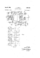
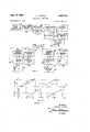
- Fig. 1 is a circuit diagram of an electrical computer embodying the present invention
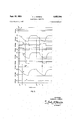
- Fig. 2 is a graph utilized in explaining the operation of the Fig. 1 arrangement
- Fig. 3 is a circuit diagram, partly schematic, of a modified form of the Fig. 1 arrangement which has a Inode of operation also represented by the graphs of Fig. 2
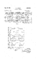
- Figs. 4, 6, 8, l0, 12, and 14 are circuit diagrams, partly schematic, of other embodiments of the invention
- Figs. 5, 7, 9, l1, 13, and 15 are graphs utilized in explaining the operation of the last-mentioned modified forms of computer.
- Fig. 1 of the drawings there is shown a circuit diagram of an electrical computer for solving equations involving known and unknown parameters and particularly well adapted for performing the mathematical operation of raising a number to a power either greater or less than unity.
- the computer comprises a plurality of circuits in the form of energy-storage networks each effective upon energization to produce a measurable effect having a value which is a predetermined function of time, the known and unknown parameters being represented by values assumed by the time functions of these effects at related times.
- One of these networks is a reference circuit I I comprising a shunt combination of an adjustable resistor R and an adjustable condenser C.
- This network is effective to develop a voltage effect varying as a predetermined function of time, specifically an exponential decay-time function, the value of which at some time represents a known parameter.
- the voltage effect Vdeveloped across the network II has a value which is solely dependent upon the value of the initial voltage applied to the network and the predetermined timeconstant characteristic thereof.
- the energication of the network II is controlled by a source of voltage E1', in the form of an adjustable battery I2 which is coupled to an outer control electrode of an energizing-circuit vacuum tube I3 the anode of which is connected to a source of space current indicated as +B.
- the cathode circuit of the tube I3 includes the network II.
- the computer also includes another energystorage network I comprising an adjustable resistor R" and shunt-connected adjustable condenser C. This network is effective upon energization thereof, at a time related to the time of the energization of the reference circuit II,
- the voltage effect developed across the network I5 has a value which is solely dependent upon the value of the initial voltage applied to the last-mentioned network and the predetermined time-constant characteristic thereof. Therefore, the value of the effect developed in either network II or I5 is electrically independent of the value of the effect developed in the other network.
- the energization of the network I5 also is controlled by a source of a voltage E1, in the form of an adjustable battery I5, coupled to another energizing-circuit vacuum tube I1.
- This vacuum tube has an outer control electrode to which the battery I5 is coupled and an anode which is energized from a space-current source +B.
- the cathode circuit of the tube Il includes the network I 5.
- a timing-pulse generator I8 is provided for repeatedly energizing both the reference network II and the controlled network I5.
- the unit I3 is a multivibrator having two vacuum tubes I9 and 2li coupled to a source of space curtrodes of the two energizing tubes I3 and II.
- the computer arrangement also includes means responsive to the value of the effect developed in the reference network II at a particular time after each of the repeated energizations thereof for evaluating the other effect developed in the Y network I5 to derive an effect which represents an unknown parameter.
- This means comprises a comparison circuit 5I coupled to the network il and a triggered pulse generator 32 having an input circuit coupled to the comparison circuit 3l and having an output circuit coupled to an input circuit of a sampling circuit 33.
- the sampling circuit also has an input circuit coupled to the controlled network I5.
- is provided with a source of voltage E2 in the form 0f an adjustable battery 34.
- the comparison circuit 3i also includes a tube 35 having a cathode-load resistor 36.
- the control electrode of the tube is connected to the battery 34, while the anode is connected to a source of space current +B.
- the cathode of the tube 35 also is coupled through a resistor 3 ⁇ I to the anode of a diode vacuum tube 33 the cathode of which is coupled to the network II.
- the anode of the tube 38 is coupled through a condenser 39 to the anode of a vacuum tube III in the pulse generator 32.
- the pulse generator 32 is of the blocking oscillator type.
- the anode of the tube 4I is coupled through one winding of a transformer 42 to a source of space current +B.
- Another winding of the transformer i2 has one terminal connected to the control electrode of the tube 4I and the other terminal coupled through a resistor 53 to a source of biasing potential indicated as -C.
- the resistor 43 also is connected to a pulse-forming delay line 44 the remote terminals of which are open-circuited. If the output signal from the comparison circuit 3l has insufcient magnitude, a pulse. amplifier may be inserted between the condenser 33 and the anode oi tube 4 I.
- the sampling circuit 33 is of the bridge-rectiier type and comprises four diode vacuum tubes 'I, 48, 49, 56 arranged in a conventional bridgerectier circuit.
- One pair of diagonal terminals of this bridge circuit is connected between the network I5 and a grounded resistor 52.
- the other pair of diagonal terminals of the bridge is connected to an actuating circuit comprising an output winding 45 provided on the transformer 42 of the unit 32.
- the actuating circuit also includes in series with the winding 45 a source of bias potential 53.
- a vacuum-tube voltmeter 54 For utilizing the effect representative of the unknown parameter, this eiiect being a voltage Ez" derived across the resistor 52, there also is provided a vacuum-tube voltmeter 54.
- rlhis volt meter includes a vacuum tube 55 having a control electrode coupled to the resistor 52 and an anode connected to a source of space current +B.
- the cathode circuit of the tube 55 comprises a condenser 55 across which is connected a voltmeter V for reading the voltage E2".
- the capacitance of condenser 55 and the resistance of the voltmeter V have values so selected as to provide for the latter element a suitably large time constant.
- the timing-pulse generator i8 operates in a conventional manner to generate across the resistor 35 a series of timing pulses of negative polarity represented by curve A. of In the computer described, lthese pulses repeat at a regular rate, and the time of starting of one such negative pulse is identied by the time t1. These negative pulses are applied to the inner control electrodes of the energizing tubes I3 and Il.
- the pulses have a magnitude ils suln cient to cause these tubes to become remain nonc-onductive for the duration of the negative timing pulses regardless of the voltages which may be applied to the outer control electrodes of tubes I3 and Il and even when the voltages developed across the networks II and I5 are quite small.
- the inner control elec trodes of the tubes I 3 and I1 Prior to the start of each negative timing pulse, the inner control elec trodes of the tubes I 3 and I1 have a positive pulse applied thereto from the generator I8 and thus permit the now of space current through the respective networks I I and I5.
- the condenser C is charged up to and maintained at the voltage E1 of ⁇ the battery I2 by virtue of the well-known cathode-follower mode oi operation of the tube i5.
- the tube 35 also operating as a cathode follower develops across its cathode-load resistor 36 a voltage E2 equal to that applied to the control electrode of the tube 35 from the bat tery 34.
- E2 the difference voltage between the voltage of the network I I and the voltage developed across the cathode resistor 36 appears across the series combination of the resistor 3l and the diode 38.
- the diode 38 conducts to develop across the resistor 31 a pulse of voltage having negative polarity. This latter voltage is applied through the condenser 39 to the pulse generator 32 at a time t2, as represented by curve C ⁇ of Fig. 2.
- rlhe leading edge of this pulse at the time t2 initiates the generation oi a single potential pulse of short duration in the pulse generator 32.
- the duration of the pulse thus generated in unit 32 is determined by the time required for a negative pulse to be reflected from the open end of the delay line 44 back to the control electrode of the tube 4I, and rthis duration is chosen just great enough to provide Y for adequate sampling of the voltage present across the network I5 at and immediately after the time t2,
- the resulting pulse from the unit 312, represented by curve D of Fig. 2, is applied from the output winding 45 of the transformer 42 to the sampling circuit 33 with proper polarity and magnitude to overcome the biasing voltage E@ of the source of potential 53. Accordingly, the bridge circuit 4l, 48, 49, 50 is actuated and rendered conductive for the duration of the applied pulse with the result that the voltage then existing across the controlled network I5 appears across the resistor 52.
- the controlled network I5 is energized under control of the tube I1 in essentially the same manner as the network II is energized under control of the tube I3. Also, the network I5 is energized at the same time t1 as is the reference network I I.
- the value E2 which the voltage across the network I 5 reaches at time t2 is dependent solely on the value E1" of the voltage initially applied to this network and the predetermined time-constant characteristic of the network I5.
- the values E2 and E2 are obtained electrically independently of one another,
- the voltage across the network II decays from the value E1 at time t1 to the value Es at time t2 in accordance with the expression:
- Equation 4 it is necessary only to adjust the batteries I2 and I6 so that the voltages E1 and E1" are equal to unity on any suitable voltage scale.
- Equation 4 then reduces to the form:
- the voltage E2 thereupon represents the parameter y and the voltage E2 represents the parameter :c of Equation 5.
- .r in Equation 5 0.6
- the time constant of the network I I is given a value relative to the time constant of the network I5 by suitable adjustments of the values of the resistors R', R and the condensers C', C" such that the ratio n of the two time constants equals 2.1, to satisfy Equation 3 above.
- voltage E2 equal 0.6 on the same scale on which the voltages of the batteries I2 and i5 were set to unity.
- the voltage E2, as read on the meter V then is found to be 0.34 which is the value of the dependent-variable parameter y of Equation 5.
- Equation 5 Another method of using the arangement of Fig. 1, when :1: in Equation 5 is greater than unity, lies in making a suitable choice for the value ci E1" in Equation 4.
- This equation can be rewrit ten as follows:
- E1" is made equal to (E1' Equation 7- the resistors R', R, and 36 at time t1 may be slightly different than the voltages E1', E1", and' E2', respectively.
- a further compensation of the voltage scale used in adjusting the battery 34 to the proper voltage may be desirable because of the slight difference in voltages between the voltage of the network II and the voltage across the resistor 35 required to cause the diode 38 to conduct.
- Fig. 3 Most of the circuit arrangement of Fig. 3 is the same as that of Fig. 1, elements which are the' rameter so that the voltage E1 to which the network I5 is charged initially must be adjusted to the value necessary to obtain the preset value of E2. Accordingly, there is included a source I6 of voltage controllable to provide the requisite voltage E1.
- the unit I6 comprises a battery 62 having a voltage E and connected to an input circuit of the energizing circuit I'I through a voltagedropping resistor 63.
- the resulting voltage E1" at the input circuit of the energizing circuit Il is read on a voltmeter 54.
- a source of voltage E2, 1n the form of an adjustable battery 64, and a control circuit 66 is included for adjusting the voltage E1 provided by the unit I6.
- the control unit 66 the voltage appearing across the output circuit of the sampling circuit 33 is developed across a tapped resistor 6'! in series withV a resistor 68.
- the resistors 6l and 38 together have such a high resistance that the rate of diS- charge of a condenser 69 connected across the two resistors in series is low.
- the unit 66 also includes two vacuum tubes 'II and l2, the cathodes of which are connected to the junction of resistors 61 and 68. is connected to the output circuit of the source I 6 while its control electrode is connected to the tap on the resistor 61.
- the scale of the voltmeter V mayy be compensated to take into account the small The accuracy
- the anode of the tube 'II ⁇ The anode 0f thev tube 12 is connected to a source of space cur' 9 rent +B, While its control electrode is connected to the battery E4.
- Equation 4 then reduces to the form:
- the voltage Ei thereupon represents the parameter y and the voltage Ei represents the parameter .r oi Equation 5.
- r 1.6 and n equal 2.1.
- Battery i2 then is adjusted to make the voltage E1 equal 1.6.
- the voltage E1 as read on the voltmeter 54', then is found to be 2.7 and indicates the value of the dependent-variable parameter y of Equation 5.
- Curve G of Fig. 2 in this case represents the voltage developed across the condenser 6.9 of the control circuit 66.
- Equation 4 By making suitable choice of the voltages Ei', E2', E1, E2", and setting the value 1t in Equation 4 equal to unity, it will be ⁇ apparent that equations of various forms may be solved. For example, if the ratio n is made unity and the voltage E1 of the Fig. 1 arrangement is adjusted to be unity, Equation 4 reduces to the form:
- Equation 4 may be rearranged to the form in which it represents the parameters of an equation having the form:
- Equation 4 may be changed to the form:
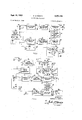
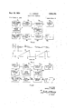
- Fig. 4 is a partly schematic circuit diagram illustrati-ng a modiiication of the Fig. 1 arrangement particularly suitable for the solution of equations of the form of Equation 10.
- a battery i2 is a source of an initial voltage preferably higher than any of the voltages representing parameters involved in the computation.
- 2 is coupled to the anode of a triode vacuum tube i3', which is included an energizing circuit for the unit Ii and has its control electrode coupled to the output circuit of the timing-pulse generator I 8. Referring to curves of 5, illustrative of the operation of the Fig.
- a timing pulse of negative polarity delivered by the unit iii ⁇ is represented by curve lei ⁇ starting at the time to.
- the ⁇ @Ondenser C" of the time-constant circuit R C of a circuit has been charged to any suitable initial voltage E0".
- the circuit I i then commences at time to to discharge exponentially, as represented by curve J of Fig'. 5.
- the circuit is coupled to a comparison circuit 3
- a pulse of positive polarity is developed across the resistor 31 and is applied through a series condenser 39 and a shunt resistor 33 to the input circuit of a univibrator 15.
- the wave form of the pulse so applied is ⁇ represented by curve K of Fig. 5.
- the time of commencement of this pulse is identified aS t1.
- the univibrator 15 is of conventional design and includes two vacuum Ytubes 16, 11 having a common cathode resistor 18.
- the anode of the tube 16 is coupled to a source of space current
- the latter control electrode is so biased as normally to .cause space-current conduction in the tube 11.
- the control electrode of tube 11 is coupled to a source of biasing potential +B through a resistor 32.
- the anode of the tube 11 is connected directly to the space-current source +B.
- the vacuum tube 16 When a positive pulse is applied by the unit 3
- Another input circuit of the energizing circuit i1 is connected to a source of a voltage E1 in the form of an adjustable battery I6.
- the energizing circuit l1 serves to Aenergize a time-constant circuit R', C in a unit l5 which at time t1 initiates an exponential discharge, represented by curve M of Fig. 5, startn ing at the voltage E1.
- the comparison circuit derives a pulse of ⁇ negative polarity represented by curve N.
- This pulse triggers the pulse generator 32 to provide a pulse of short duration having the wave form represented by curve P.
- the latter iilse is applied to actuate a sampling circuit
- the timing-pulse generator i8' has applied, at time to, a timing pulse of negative polarity to an energizing circuit 86 coupled to the battery I6'.
- Equation 16 may be evaluated by substituting in it the value of t2 obtained from Equations 14 and 15. From Equation 14:
- Equation 25 Equation 25 becomes:
- Eo will decay from 100 to 40 volts in the total time required for Eo" to decay from 10 to 5 volts plus the time required for E1 to decay from l0 to 8 volts.
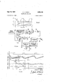
- FIG. 6 The block diagram of Fig. 6 represents another modied form of the invention essentially similar to that of Fig. 1.
- a source of a conveniently high initial voltage En provided by a battery IZ' is applied to an energizing circuit I3' controlled from a timingpulse generator I8 so as to energize a timeconstant circuit R', C in a unit Il'.
- the timing pulse from generator I8' is applied to a triggered pulse generator 32 to develop a pulse of short duration which is applied to an adjustable delay circuit 9i
- This delay circuit includes a rod or strip 92 of magnetostrictive material having energy-absorbing clamps 93, 93 at the ends thereof.
- the output circuit of the pulse generator 32 is coupled to a coil 94 magnetically coupled to the strip 92 and adjustable therealong.
- An output coil 95 also magnetically coupled to the strip 92, is coupled to the input circuit of a pulse-shaping circuit 97 of conventional construction.
- the input circuit of the pulse-shaping circuit 91 may include a source of biasing current for the output coil as is desirable to obtain a desirable magnetic condition in the magnetostrictive strip 92 in the region of the output coil 95.
- are described and claimed in the following copending applications: Alan Hazeltine, Serial No. 785,248, led November 12, 1947, entitled Magnetostrictve Signal-Translating Arrangement, now Patent No. 2,526,229; Theodore J.
- the timing pulse of negative polarity developed in the generator I8 of Fig. 6 is represented by curve S.
- the leading edge of the negative timing pulse causes the generation at a time to of a pulse of short duration in the pulse generator 32', as represented by curve T.
- This pulse is applied to the delay circuit 9
- the delayed pulse induced in the coil 95 has the form represented by curve U and oc'- curs at the time t2.
- the leading edge of the pulse generated in the univibrator 15 energizes at the time t1 the timeoonstant circuit R", C in the unit I5, through the action of an energizing circuit I1 having an input circuit coupled to the univibrator 15 and an output circuit coupled to the circuit I5.
- a voltage Ei provided by an adjustable battery I6 is applied to another input circuit of the energizing circuit I1, so that the voltage in the circuit I5 at the time of its energization is E1.
- the delayed pulse, curve U, of the pulse-shaping circuit 91 actuates a sampling circuit 33 coupled to the time-constant circuit I5 to derive therefrom a voltage E2, which is indicated on the voltmeter 54.
- the curve Y represents the voltage of the circuit I5, and the curve Z represents the voltage E2 derived in the sampling circuit 33.
- Equation 4 Assuming the time constants of the two circuits and I5 to be the same., the Equation 4 reduces to the form:
- Equation 29 may be given the form:
- the voltage E2' may happen to occur at a point of the exponential discharge of the condenser C where the slope of curve V is relatively small so thaJ the circuit would be insensitive to physical measurements at the time t2.
- En is a voltage greater than any value which the voltage E1 may assume and, although arbitrary, must be maintained constant during successive computations because it alects the time interval t2-to.
- a controlling pulse representing the internal tz-tu is obtained in the Fig. 6 arrangement by the setting of the movable coil 9400i the delayhcircuit 9
- the voltages E2 and Ei" of Equation 30 may be used as representative of the parameters l1,/ Vand respectively, of Equation 31. If the values of Ei" and Ez', Equations 29 and 30, are chosen so that the constant lc equals unity, then the Fig. 6 .arrangement maybe used to determine the reciprocal y of the parameter a: of Equation 3l.
- Fig. 8 is a circuit diagram, partly schematic, representing an .embodiment of the invention useful for Aperforming addition or subtraction.
- all of the variables involved are ⁇ represented by a voltage relative to ground which is proportional to the variable.
- a timing.- pulse generator I8 triggers a single-sweep sawtootli circuit 9
- a zero-adjusting circuit 92 is included ⁇ to provide for the initiation of the saw-tooth wave at Yaero voltage at the .time tu.
- This circuit comprises a .coupling condenser ⁇ 93 included in series with a.
- resistor 94 across the output circuit of the 4unit 9
- a suitable single-sweep saw-tooth circuit is disclosed in Principles of Radar, published by McGraw-Hill Fublishing Co., Inc., New York, N. Y. (second edition, 1946) pages 3-2(), Fig. 10.
- the saw tooth represented by curve AA .of Fig. V9 reaches a value E1' as determined by a source I6 of ⁇ voltage E1.
- a comparison circuit 3 I then develops a potential pulse adapted to cause the generation of a potential pulse in a univibrator 15 having a wave form suitable ⁇ .for ⁇ energizing another single-sweep saw-tooth circuit 91.
- VThe latter ⁇ then develops a saivetooth voltage starting at the time ti and represented by the curve BB of Fig. 9.
- provides a zero reference voltage Vfor the saw-tooth wave of curve BB.
- the output circuit of the adjusting circuit 918 is connected to the switch blade of a singlepole double-throw switch
- the sawtooth circuit 91 is coupled through the adjusting circuit 98 to a sampling circuit 33, to an output circuit of which is connected a voltmeter 54.
- is coupled through the ad- ⁇ iusting circuit 92 to a comparison circuit 3
- produces a potential pulse which is utilized to trigger a pulse generator 32 to produce a pulse suitable for actuating the sampling circ-uit 33. The latter then samples the voltage of the sawtooth circuit 51 to derive the corresponding voltage E2 which is indicated bythe voltmeter 54.
- Equation 32 The values of the voltages in Equation 32 may Irepresent the corresponding parameters of the equation:
- the Fig. 8 arrangement is useful to perform additions.
- the voltage of the saw-tooth circuit 91 is compared in a comparison circuit 3
- the voltage of the saw-tooth circuit 91 reaches the voltage E2 and a poential pulse is developed in the comparison circuit 3
- the latter circuit is coupled to the saw-tooth circuit 9
- Equation 32 may be rearranged in the form:
- the values of the voltages in Equation 34 may represent the parameters of the equation:
- Substantially linear time functions such as those developed in the saw-tooth circuits of the Fig. 8 arrangement also may be used for multiplying a number by a factor greater or less than unity.
- An arrangement of this type is represented by the block diagram of Fig. 10 and the curves of Fig. 1l.
- a timing-pulse generator I8 causes the initiation at a time to of a substantially linear saw-tooth wave of voltage in a reference saw-tooth circuit 9
- the wave forms of the voltages developed in the two circuits 92 and 93 are represented by the curves CC and DD, respectively, of Fig. 11.
- the adjusting circuit 92 is coupled to a comparison circuit 3
- triggers a pulse generator 32 to'develop a potential pulse suitable for actuating a sampling circuit 33 to which the adjusting circuit 98 is coupled.
- the voltage E1 then present in the saw-tooth circuit 91 is derived in the sampling circuit 33 and may be indicated on a voltmeter 54.
- Equation x ay (38)
- An arrangement of this type may be used, for example, to multiply the parameter 1j by any convenient constant a such as l0.
- a computer of the type described is used to solve an equation represented by the voltages of Equation l0 hereinabove, and the range of voltages over which the voltage E2 in that equation may vary is such that the voltage E2 is always quite small, this voltage may be multiplied by any constant such as 10 by using a computer of the Fig. 10 type.
- the resulting voltage is then applied as a source oi voltage E2 of the next higher order of magnitude to the computer for performing multiplication, as in computation involving an equation of the type represented by Equation ll.
- the product e read from the computer then must be divided by the constant a employed, for example 10, to obtain the ⁇ correct solution.
- the Fig. l0 arrangement has the advantage of a fixed accuracy no matter when the time t1 occurs along the saw tooth, and may be made to multiply or divide by large factors because of the linearity of the circuits available for generating voltages of sawtooth Wave form. Since the amplitudes of the saw-tooth wave forni increase rather than decrease with time, the only limit to the voltages which may be measured is imposed by the duration of the saw-tooth Wave of voltage'itself.
- one of the computation eiects varies as a time function analogous to an equation to be solved.
- a timing-pulse generator i8 causes the energization of both a single-sweep saw-tooth circuit 91 and, through an energizing circuit I3, the time-constant circuit R', C of ⁇ a unit
- Both of the units il and 91 are energized at a time which is indicated to in the explanatory curves of Fig. 13.
- a voltage En as determined by the adjustment of a source I2 of such a voltage.
- the resulting exponentially decaying voltage in the circuit Il is represented by curve FF of Fig. 13, While the saw-.tooth circuit 9.1 is provided with a zero-adjusting circuit 93 which develops a voltage represented by curve GG of Fig. i3.
- develops a potential pulse adapted to trigger a pulse generator 32 which in turn provides a potential pulse for actuating a sampling circuit 33 having an input circuit coupled to the adjusting circuit 98.
- the circuit i reaches the voltage E1 at a time ti
- the voltage E1" in the adjusting circuit 98 is derived at that time in the sampling circuit 33 and is indicated on the voltmeter E.
- Equation Li3 The voltage developed by the saw-tooth circuit 91 4.EVEN Efmoie'n '0' 43) Equation Li3 maybe transformed into the form:
- the voltage E1" may be made 4to represent -the .dependent variable .andthe-voltage E1 to represent the independent variable, so that rEquation 48 takes the form:
- Fig. 12 arrangement may be used for ending iogarithms andantilocarithms :to any .desired base.
- fthe ltiming-pulse generator I8 is coupled through a ⁇ single-sweep saw-tooth circuit -91 to a zero-adjusting circuit 02.
- the output ⁇ circuit -of the latter ⁇ coupled to a phase-control circuit ⁇ which-includes ⁇ a voltage divider
- 2 is connected to a xed contact T of a singlepole ⁇ double-throwswitch .
- 03 viscoupled ⁇ to thehputcircut of 18 a comparison kcircuit 3
- the output circuit Aof the timing-pulse generator I8 is also coupled to a sine-Wave ringing generator
- 2 is adjustably coupled to the inductor
- 8 and represented by curve HH is applied to the saw-tooth circuit 91 to initiate a signal of saw-tooth wave form represented .by curve JJ.
- the signal o f periodic-pulse wave form generated ⁇ by the generator :I8 is also applied to the sine-wave ringing ⁇ generator
- 06 is biased to anode-current cutoii at the trailing edge of each pulse. The consequent sudden conduction of space current through the tube
- 03 and It are moved to close their contacts T so that the phase-.adjusting circuit
- the triggered pulse generator 32 When the voltage translated through the phase-control circuit
- 05 initiates the generation at time tu of oscillations in its resonant circuit
- the voltage thus applied to the sampling 'circuit 33. at anytime t is therefore given by the relation:
- Equation 54 The value of the timetl is thus seen from Equation 54 to have the value:
- Equation 60 Equation 60 becomesof the form:
- an electrical computer involving the invention is applicable generally to solving equations the solutions of which involve the common mathematical relationships and yet is one free of mechanical moving parts, is compact and of small weight, and is capable of computation at high speeds.
- the computer of the invention is capable of continuously and rapidly recalculating a problem involving parameters subject to change, and is well adapted to perform algebraic operations in which all of the independent and dependent variables are represented by voltages referred to a conventional reference datum voltage.
- An electrical computer for solving equations involving known and unknown parameters comprising: an electrical reference circuit having circuit elements With resistance and reactance values so proportioned as todevelop an electrical effect varying as a predetermined time function the value of which at some time represents a known parameter of an equation to be solved; a source of potential having a value representative of a parameter of said equation; means for utilizing said potential of said source and said effect at said predetermined time to develop a control effect; an electrical controlled circuit having circuit elements with resistance and reactance Values so proportioned as to developanother electrical effect having a value electrically independent of the value of said first-mentioned effect and Varying as a predetermined time function a value of which at some time is related to the value of an unknown parameter of said equation; means responsive to said control effect for evaluating said other effect to derive a resultant eifect which represents an unknown parameter of said equation; and means forutilizing said resultant effect.
- An electrical computer for solving equations involving known and unknown parameters comprising: an electrical reference circuit having circuit elements with resistance and reactance values so proportioned as to develop an electrical effect varying as a predetermined time function which at an instant'of time determined by an independent variable known parameter of an equation to be solved reaches a value representing said known parameter; a source of potential having a value representative of said independent variable known parameter; means for utilizing said potential of said source and said eifect at said predetermined time to develop a control effect; an electrical controlled circuit having circuit elements with resistance and reactance values so proportioned as to develop another electrical effect having a value electrically independent of the value of said first-mentioned effect and Varying as a predetermined time function a value of which at some time is related to the value of an unknown parameter of said equation; means responsive to said controlelfect for evaluating said other effect to derive a resultant effect which represents an unknown parameter of said equation; and means for utilizing said resultant effect.
- An electrical computer for solving equations involving known and unknown parameters comprisingzan electrical reference circuit having circuit elements with resistance and reactance Values so proportioned as to develop an electrical effect varying as apredetermined time function the value of which at some time ⁇ represents a known parameter of an equation to be solved; a source of potential having @Value representative of a parameter of said equa-tion; means for utilizing said potentialof sadsource and ys aid eifect at said predetermined timetodevelop a control effect; an electrical controlled circuit having circuit elements with resistancel and reactance values so proportioned as tode'velop another electrical effect having a value electrically independent of the value of said first-mentioned effect and varying as a predetermined time function a value of which at sometime is related.
- An electrical computer forsolving equations involving known and ⁇ unknown parameters comprising: a first impedance network having circuit elements with resistance and reactance values so proportioned as to develop an electrical effect varying as a predetermined time function the value of which at some time represents a known parameter of an equation to be solved; a source of potential having a value representative of a parameter of said equation; means for utilizing said potential of said source and-said effect at said predetermined time to develop a control effect; a second impedance network having'circuit elements with resistance and reactance values so proportioned as to develop another electrical effect having a value electrically independent of the value of said first-mentioned effect and varying as a predetermined time function a value of which at some time is related to the value of an unknown parameter of said equation, at least one of said functions varying as a substantially Vlinear function of time; means responsive to said control effect for evaluating said other effect to derive a resultant effect which represents an unknown parameter of said equation; and means for utilizing said resultant effect.
- An electrical computer for solving equations involving known and unknown'parameters comprising: an electrical reference circuit having circuit elements with resistance and reactance values so proportioned as to develop an electrical effect varying as a predetermined substantially linear time function the value of which at some time represents a known parameter of an equation to be solved; a source of potential having a value representative of a parameter of said equation; a signal-comparison circuit for combining said potential of said source and said effect at said predetermined time to develop a control effect; an electrical controlled circuit having circuit elements with resistance and reactance values so proportioned as to develop another electrical effect having a value electrically independent of the value of said first-mentioned effect and varying as a predetermined substantially linear time function a value of which at some 'time is related to the value of an unknown parameter of said equation; means responsive to said control effect for evaluating said other effect to derive a resultant effect which represents an unknown parameter of said equation; and means for utilizing said resultant effect.
- An electrical computer for solving equations involving known and unknown parameters comprising: an electrical reference circuit having .circuit elements with resistance and reactance values so proportioned as to develop an electrical effect varying as a predetermined time function the value of which at some time represents a known parameter of an equation to be solved; a source of potential :having a value represents/tive of a parameter of said equation; means coupled to said reference circuit and said source for utilizing said potential of said source and said effect at said predetermined time to develop a ⁇ control effect; an electrical controlled circuit having circuit elements with resistance and reactance values so proportioned as to develop another electrical effect having a value electrically independent of the value of said firstmentioned effect and varying ⁇ as a predetermined time function a value of which at some time is related to the value of an unknownparameter of said equation, at least one of said effects varying as a trigonometric function of time; means responsive to said control effect for evaluating said other effect to derive a resultant effect which represents an unknown parameter of said equation; and means
- An electrical computer for solving equations involving known and unknown parameters comprising: a first time-constant circuit having circuit elements with resistance and reactance values so proportioned as'to develop an electrical effect varying as a predetermined time function the value of which at sometime represents a known parameter of an equation to be solved; ⁇ a source of potential having a value representative of a parameter of said equation; an electron-discharge device for comparing said potential of said source and said effect at said predetermined timeto develop a control effect; a second timeconstant circuit having circuit elements with resistance and reactance values so proportioned as to develop another electrical effect having a value electrically independent of the value of said first-mentioned effect and varying as a predetermined time function a value of which at some time is related to the value of anunknownparameter of said equation, at least one of said effects varying as an exponential function of time; means responsive to said control effect for evaluating said other eifect to derive a resultant effect which represents an unknown parameter of said equation; and means Vfor utilizing said resultant
- An electrical computer for solving equations involving known and unknown parameters comprising: a first'adjustable time-constant circuit having circuit elements with resistance and reactance values so proportioned as to develop an electrical effect varying as a predetermined time function the value of which at some time represents a known parameter of an equation to be solved; a source of potential having a value representative of a parameter of said equation; means for utilizing said ⁇ potential of said source and said effect at said predetermined time to develop a control effect; a second adjustable timeconstant circuit having circuit elements with resistance and reactance ⁇ values so proportioned as to develop another electrical effect having a value electrically independent of the value of said firstmentioned effect and varying as a predetermined time function a value of which at some time is related to the value of an unknown parameter of said equation, at least one of said effects varying as an exponentially decaying .function of time; means responsive to said control effect for evaluating said other effect to derive a resultant effect which represents an unknown parameter of said equation; and means for utilizing
- An electrical computer for solving equations involving known and unknown parameters comprising: an electrical reference circuit having circuit elements with resistance and reactance values so proportioned as to develop an electrical effect varying as a predetermined exponential time function the value of which at some time represents a known parameter of an equation to be solved; a source of potential having a value representative of ⁇ a parameter of :said equation;
- an electrical controlled circuit having circuit elements with resistance and reactance values so proportioned as to develop another electrical effect having a value electrically independent of the value of said firstmentioned effect and varying as a predetermined exponential time function a value of which at some time is related to the value of an unknown parameter of said equation; means responsive to said control effect for evaluating said other effect to derive a resultant effect which represents an unknown parameter of said equation; and means for utilizing said resultant effect.
- An electrical computer for solving equations involving known and unknown parameters comprising: an electrical reference circuit having circuit elements with resistance and reactancevalues so proportioned as to develop an electrical effect varying as a predetermined exponential decaying time function the value of which at some time represents a known parameter of an equation to be solved; a source of potential having a value representative of a parameter of said equation; means for utilizing said potential of said source and said effect at said predetermined time to develop a control effect; an electrical controlled circuit having circuit elements with resistance and reactance values so proportioned as to develop another electrical effect having a value electrically independent of the value of said firstmentioned effect and varying as a predetermined exponential decaying time function a value of which at some time is related to the value of an unknown parameter of said equation; means responsive to said control effect for evaluating said other effect to derive a resultant effect which represents an unknown parameter of said equation; and means for utilizing said resultant effect.
- An electrical computer for solving equations involving known and unknown parameters comprising: an electrical reference circuit having circuit elements with resistance and reactance values so proportioned as to develop an electrical effect varying as a predetermined time function the value of which at some time represents a known parameter of an equation to be solved; a source of potential having a value representative of a parameter of said equation; means for utilizing said potential of said source and said effect at said predetermined time to develop a control effect; an electrical controlled circuit having circuit elements with resistance and reactance values so proportioned as to develop another electrical effect having a value electrically independent of the value of said firstmentioned effect and varying as a predetermined time function a value of which at some time is related to the value of an unknown parameter of said equation, at least one of said circuits being an energy-storage network; means responsive to said control effect for evaluating said other effect to derive a resultant effect which represents anunknown parameter of said equation; and means for utilizing said resultant effect.
- An electrical computer for solving equations involving known and unknown parameters comprising: an electrical reference energy-storage network having circuit elements with resistance and reactance values so proportioned as to develop an electrical effect varying as a predetermined exponentially decaying time function the value of which at some time represents a known parameter of an equation to be solved; a
- an electrical controlled energy-storage network having circuit elements with resistance and reactance values so proportioned as to develop another electrical effect having a value electrically independent of the value of said firstmentioned effect and varying as a predetermined exponentially decaying time function a value of which at some time is related to the value of an unknown parameter of said equation; means responsive to said control effect for evaluating said other effect to derive a resultant effect which represents an unknown parameter of said equation; and means for utilizing said resultant effect.
- An electrical computer for solving equations involving known and unknown parameters comprising: an electrical reference circuit having circuit elements with resistance and reactance values so proportioned as to develop upon energization an electrical effect varying as a predetermined time function the value of which at some time after said energization represents a known parameter of an equation to be solved; a source of potential having a value representative of a parameter of said equation; means for utilizing said potential of said source and said effect at said predetermined time to develop a control effect; an electrical controlled circuit having circuit elements with resistance and reactance values so proportioned as to develop upon energization thereof at a time related to the time of said energization of said reference circuit another electrical effect having a value electrically independent of the value of said rst-mentioned effect and Varying as a predetermined time function a value of which at some time is related to the value of an unknown parameter of said equation; ⁇ means responsive to said control effect for evaluating said other effect to derive a resultant effect which represents an unknown parameter of said equation;
- An electrical computer for solving equations involving known and unknown parameters comprising: an electrical reference circuit having circuit elements with resistance and reactance values so proportioned as to develop upon energization an electrical effect varying as a predetermined time function the value of which at some time after said energizaticn represents a known parameter of an equation to be solved; means for repeatedly energizing said reference circuit; a source of potential having a value representative of a parameter of said equation; means for utilizing said potential of said source and said effect at said predetermined time after each of said repeated energizations to develop a'control effect; an electrical controlled circuit having circuit elements with resistance and reactance values so proportioned as to develop upon each similarly repeated energization thereof another electrical effeot having a value electrically independent of the value of said rst-mentioned effect and varying as a predetermined time function a value of which at some time is related to the value of an unknown parameter of said equation; means responsive to each of said control effects for evaluating said other effect to derive
- an electricalreference circuit having circuit elements with resistance and reactance values so proportioned as to develop upon energization an electrical effect varying asa predetermined time function which, at an instant of time after said energization asfcletermined by an independent variable known parameter of an equation to be solved, reaches a value represent ing said known parameter; means for repeatedly energizing said reference circuit; a source of potential having a value representative of a parameter of said equation; means for utilizing said potential of said source and said effect at said predetermined time after each of said repeated energizations to develop a control effect; an electrical controlled circuit having circuit elements with resistance and reactance values so proportioned as to develop upon each similarly repeated energization thereof another electrical effect having a value electrically independent of the value of said first-mentioned effect and varying as a predetermined time function a value of which at some time is related to the value of an unknown parameter of said equation variable
- An electrical computer for solving equations involving known and unknown parameters comprising: a plurality of electrical circuits each with resistance and reactance values so proportioned as to develop upon energization a measurable electrical effect having a Value which is a predetermined function of time, said known and unknown parameters being represented by values assumed by the time functions of said effects at related times; means for energizing at least one of said circuits to produce at least one of said effects; a source of potential having a value representative of a known parameter of said eduation for determining a first instant of time at which the value of the effect produced by said one circuit represents one of said known parameters; means for utilizing said potential of said source and one of said effects at said first instant of time to develop a control effect; said energizing means also being so proportioned as to initiate energization of at least one other of said circuits at a time related to said first instant of time to produce at least another of said electrical effects having a value independent of the value of said one of said effects; means ef
- An electrical computer for solving equations involving known and unknown parameters comprising: a plurality of electrical circuits each with resistance and reactance values so proportioned as to develop upon energization a measurable electrical effect having a value which is a predetermined function of time, at least one of said effects having a value varying as a substantially linear function of time and said known and unknown parameters being represented by values assumed by the time functions of said effects at related times; means for energizing at least one of said circuits to produce at least .one
- a source of potential having' a value representative of a known parameter of said equationfor determining a first instant of time at which-the value of the effect produced by said one circuit represents one of said known parameters; means for utilizing saidpotential of said source and one of said effects at said rst instant of time to develop a control effect; said energizing means also being so proportioned as to initiate energization of at least one other of said circuits at a time related tosaid first instant of time to produce at least another of said electrical effects having a value independent of the value of said one of said effects; means effectively responsive to saidV control effect fordetermining a second instant of time at which the value of another of said effects represents an unknown parameter; and means for utilizing said other effect representative of said unknown parameter.
- An electrical computer for solving equations involving known and unknown parameters comprising: a plurality of electrical circuits each with resistance and reactance values so proportioned as to develop upon energization of measurable electrical effect having a value which is a predetermined function of time, at least one of said effects having a value varying as a trigonometric function of time and said known and unknown parameters being represented by values assumed by the time functions of said effects at related times; means for energizing at least one of said circuits to produce at least one of said effects; a source of potential having a value representative of a known parameter of said equation for determining a rst instant of time at which the value of the effect produced by said one circuit represents one of said known parameters; means for utilizing said potential of said source and one of said effects at said first instant of time to develop a control effect; said energizing means also being so proportioned as to initiate energization of at least one other of said circuits at a time related -to said rst instant of time to produce
- An electrical computer for solving equations involving known and unknown parameters comprising: a plurality of electrical circuits each with resistance and reactance values so proportioned as to develop upon energization a measurable electrical effect having a value which is a predetermined function of time, at least one of said effects having a value varying as an exponential function of time and said known and unknown parameters being represented by values assumed by the time functions of said effects at related times; means for energizing at least one of said circuits to produce at least one of said effects; a source of potential having a value representative of a known parameter of said equation for determining a rst instant of time at which the value of the effect produced by said one circuit represents one of said known parameters; means for utilizing said potential of said source and one of said effects at said first instant of time to develop a control effect; said energizing means also being so proportioned as
Landscapes
- Physics & Mathematics (AREA)
- Engineering & Computer Science (AREA)
- Mathematical Physics (AREA)
- Theoretical Computer Science (AREA)
- General Physics & Mathematics (AREA)
- Software Systems (AREA)
- Computer Hardware Design (AREA)
- Mathematical Analysis (AREA)
- Algebra (AREA)
- Mathematical Optimization (AREA)
- Pure & Applied Mathematics (AREA)
- Power Engineering (AREA)
- Feedback Control In General (AREA)
- Tests Of Electric Status Of Batteries (AREA)
- Control Of Eletrric Generators (AREA)
- Measurement Of Resistance Or Impedance (AREA)
- Measurement Of Current Or Voltage (AREA)
- Generation Of Surge Voltage And Current (AREA)
- Electrotherapy Devices (AREA)
Priority Applications (11)
| Application Number | Priority Date | Filing Date | Title |
|---|---|---|---|
| BE487637D BE487637A (de) | 1948-03-02 | ||
| NL717102029A NL145103B (nl) | 1948-03-02 | Elektrische verbindingsinrichting voor het elektrisch verbinden van een elektrisch onderdeel en een geleidende baan op een isolatiepaneel. | |
| US12633A US2652194A (en) | 1948-03-02 | 1948-03-02 | Electrical computer |
| CH275493D CH275493A (de) | 1948-03-02 | 1949-02-07 | Elektrisches Rechengerät. |
| DEP33907D DE815559C (de) | 1948-03-02 | 1949-02-11 | Elektrisches Rechengeraet |
| GB4279/49A GB663225A (en) | 1948-03-02 | 1949-02-16 | Electrical computer |
| FR987026D FR987026A (fr) | 1948-03-02 | 1949-02-22 | Machine à calculer électrique |
| US119637A US2671608A (en) | 1948-03-02 | 1949-10-05 | Electrical computer |
| GB22871/50A GB681500A (en) | 1948-03-02 | 1950-09-18 | Electrical computer |
| US225721A US2666576A (en) | 1948-03-02 | 1951-05-11 | Electrical computer |
| GB10221/52A GB710916A (en) | 1948-03-02 | 1952-04-23 | Electrical computer |
Applications Claiming Priority (3)
| Application Number | Priority Date | Filing Date | Title |
|---|---|---|---|
| US12633A US2652194A (en) | 1948-03-02 | 1948-03-02 | Electrical computer |
| US119637A US2671608A (en) | 1948-03-02 | 1949-10-05 | Electrical computer |
| US225721A US2666576A (en) | 1948-03-02 | 1951-05-11 | Electrical computer |
Publications (1)
| Publication Number | Publication Date |
|---|---|
| US2652194A true US2652194A (en) | 1953-09-15 |
Family
ID=27359667
Family Applications (3)
| Application Number | Title | Priority Date | Filing Date |
|---|---|---|---|
| US12633A Expired - Lifetime US2652194A (en) | 1948-03-02 | 1948-03-02 | Electrical computer |
| US119637A Expired - Lifetime US2671608A (en) | 1948-03-02 | 1949-10-05 | Electrical computer |
| US225721A Expired - Lifetime US2666576A (en) | 1948-03-02 | 1951-05-11 | Electrical computer |
Family Applications After (2)
| Application Number | Title | Priority Date | Filing Date |
|---|---|---|---|
| US119637A Expired - Lifetime US2671608A (en) | 1948-03-02 | 1949-10-05 | Electrical computer |
| US225721A Expired - Lifetime US2666576A (en) | 1948-03-02 | 1951-05-11 | Electrical computer |
Country Status (7)
| Country | Link |
|---|---|
| US (3) | US2652194A (de) |
| BE (1) | BE487637A (de) |
| CH (1) | CH275493A (de) |
| DE (1) | DE815559C (de) |
| FR (1) | FR987026A (de) |
| GB (3) | GB663225A (de) |
| NL (1) | NL145103B (de) |
Cited By (10)
| Publication number | Priority date | Publication date | Assignee | Title |
|---|---|---|---|---|
| US2700501A (en) * | 1951-12-28 | 1955-01-25 | Wang An | Voltage detector |
| US2880935A (en) * | 1954-09-27 | 1959-04-07 | Gilfillan Bros Inc | Means for electronic multiplication |
| US2934274A (en) * | 1957-07-31 | 1960-04-26 | Itt | Voltage ratio device |
| US2966306A (en) * | 1955-07-02 | 1960-12-27 | Zenith Radio Corp | Computing apparatus |
| US2978178A (en) * | 1954-01-13 | 1961-04-04 | Sun Oil Co | Computing circuits |
| US3021064A (en) * | 1955-05-24 | 1962-02-13 | Digital Control Systems Inc | Ordered time interval computing systems |
| US3048337A (en) * | 1957-07-02 | 1962-08-07 | Westinghouse Electric Corp | Electron means for generating trigonometric functions |
| US3141969A (en) * | 1960-05-03 | 1964-07-21 | Curtiss Wright Corp | Method of and apparatus for performing computations |
| US3268661A (en) * | 1962-04-09 | 1966-08-23 | Melpar Inc | System for determining consonant formant loci |
| CN110648621A (zh) * | 2019-10-30 | 2020-01-03 | 京东方科技集团股份有限公司 | 移位寄存器及其驱动方法、栅极驱动电路及显示装置 |
Families Citing this family (15)
| Publication number | Priority date | Publication date | Assignee | Title |
|---|---|---|---|---|
| US3126904A (en) * | 1964-03-31 | Response in automatic control | ||
| US2971698A (en) * | 1955-03-14 | 1961-02-14 | Gilfillan Bros Inc | Function generating circuits requiring only linear elements |
| US2901173A (en) * | 1955-10-20 | 1959-08-25 | Labinal Ets | Apparatus for measuring the product of two concurrently varying quantities |
| US3004707A (en) * | 1955-11-17 | 1961-10-17 | Robert E Wilson | Pulse center determining system |
| US2926852A (en) * | 1956-05-01 | 1960-03-01 | Hughes Aircraft Co | Electronic resolver |
| GB745816A (en) * | 1956-08-27 | 1956-03-07 | Bendix Aviat Corp | Improvements in digital integrating devices, particularly adapted for differential analysis |
| US2947480A (en) * | 1956-10-15 | 1960-08-02 | Hazeltine Research Inc | Electrical differentiator |
| US3050253A (en) * | 1958-11-17 | 1962-08-21 | Phillips Petroleum Co | Detector for sensing small rate of change signals |
| US3022005A (en) * | 1959-01-12 | 1962-02-20 | Ibm | System for comparing information items to determine similarity therebetween |
| NL255345A (de) * | 1959-08-31 | |||
| US3131296A (en) * | 1961-04-13 | 1964-04-28 | Erik V Bohn | Pulse position analog computer |
| US3205348A (en) * | 1961-09-28 | 1965-09-07 | Gulton Ind Inc | Quotient circuit |
| DE1260204B (de) * | 1963-03-20 | 1968-02-01 | Versuchsanstalt Fuer Luftfahrt | Schaltungsanordnung zur Erzeugung einer Spannung aus drei gegebenen Spannungen A, B,C, die der Spannung A und einer Funktion des Verhaeltnisses B/C proportional ist |
| CH446740A (de) * | 1965-04-15 | 1967-11-15 | Philips Nv | Analog-Digital-Wandler |
| DE2806596C2 (de) * | 1978-02-16 | 1979-11-29 | Danfoss A/S, Nordborg (Daenemark) | Anordnung zum Potenzieren eines Signals |
Citations (5)
| Publication number | Priority date | Publication date | Assignee | Title |
|---|---|---|---|---|
| US2313666A (en) * | 1940-01-26 | 1943-03-09 | Rca Corp | Logarithmic instrument circuit |
| US2401729A (en) * | 1941-12-06 | 1946-06-11 | Alfred N Goldsmith | Impulse counting and selecting device |
| US2403873A (en) * | 1942-08-06 | 1946-07-09 | Ncr Co | Impulse emitter |
| US2422698A (en) * | 1942-11-05 | 1947-06-24 | Bell Telephone Labor Inc | Time measuring system |
| US2433254A (en) * | 1946-01-07 | 1947-12-23 | Aiken William Ross | Electrical timing system |
Family Cites Families (4)
| Publication number | Priority date | Publication date | Assignee | Title |
|---|---|---|---|---|
| US2412467A (en) * | 1942-04-30 | 1946-12-10 | Rca Corp | Electronic computer |
| US2426910A (en) * | 1944-01-27 | 1947-09-02 | Rca Corp | Measurement of time between pulses |
| US2594731A (en) * | 1949-07-14 | 1952-04-29 | Teleregister Corp | Apparatus for displaying magnetically stored data |
| US2558430A (en) * | 1949-07-30 | 1951-06-26 | Rca Corp | Polynomial equation solver |
-
0
- BE BE487637D patent/BE487637A/xx unknown
- NL NL717102029A patent/NL145103B/xx unknown
-
1948
- 1948-03-02 US US12633A patent/US2652194A/en not_active Expired - Lifetime
-
1949
- 1949-02-07 CH CH275493D patent/CH275493A/de unknown
- 1949-02-11 DE DEP33907D patent/DE815559C/de not_active Expired
- 1949-02-16 GB GB4279/49A patent/GB663225A/en not_active Expired
- 1949-02-22 FR FR987026D patent/FR987026A/fr not_active Expired
- 1949-10-05 US US119637A patent/US2671608A/en not_active Expired - Lifetime
-
1950
- 1950-09-18 GB GB22871/50A patent/GB681500A/en not_active Expired
-
1951
- 1951-05-11 US US225721A patent/US2666576A/en not_active Expired - Lifetime
-
1952
- 1952-04-23 GB GB10221/52A patent/GB710916A/en not_active Expired
Patent Citations (5)
| Publication number | Priority date | Publication date | Assignee | Title |
|---|---|---|---|---|
| US2313666A (en) * | 1940-01-26 | 1943-03-09 | Rca Corp | Logarithmic instrument circuit |
| US2401729A (en) * | 1941-12-06 | 1946-06-11 | Alfred N Goldsmith | Impulse counting and selecting device |
| US2403873A (en) * | 1942-08-06 | 1946-07-09 | Ncr Co | Impulse emitter |
| US2422698A (en) * | 1942-11-05 | 1947-06-24 | Bell Telephone Labor Inc | Time measuring system |
| US2433254A (en) * | 1946-01-07 | 1947-12-23 | Aiken William Ross | Electrical timing system |
Cited By (12)
| Publication number | Priority date | Publication date | Assignee | Title |
|---|---|---|---|---|
| US2700501A (en) * | 1951-12-28 | 1955-01-25 | Wang An | Voltage detector |
| US2978178A (en) * | 1954-01-13 | 1961-04-04 | Sun Oil Co | Computing circuits |
| US3047232A (en) * | 1954-01-13 | 1962-07-31 | Sun Oil Co | Computing circuits |
| US2880935A (en) * | 1954-09-27 | 1959-04-07 | Gilfillan Bros Inc | Means for electronic multiplication |
| US3021064A (en) * | 1955-05-24 | 1962-02-13 | Digital Control Systems Inc | Ordered time interval computing systems |
| US2966306A (en) * | 1955-07-02 | 1960-12-27 | Zenith Radio Corp | Computing apparatus |
| US3048337A (en) * | 1957-07-02 | 1962-08-07 | Westinghouse Electric Corp | Electron means for generating trigonometric functions |
| US2934274A (en) * | 1957-07-31 | 1960-04-26 | Itt | Voltage ratio device |
| US3141969A (en) * | 1960-05-03 | 1964-07-21 | Curtiss Wright Corp | Method of and apparatus for performing computations |
| US3268661A (en) * | 1962-04-09 | 1966-08-23 | Melpar Inc | System for determining consonant formant loci |
| CN110648621A (zh) * | 2019-10-30 | 2020-01-03 | 京东方科技集团股份有限公司 | 移位寄存器及其驱动方法、栅极驱动电路及显示装置 |
| CN110648621B (zh) * | 2019-10-30 | 2023-04-18 | 京东方科技集团股份有限公司 | 移位寄存器及其驱动方法、栅极驱动电路及显示装置 |
Also Published As
| Publication number | Publication date |
|---|---|
| NL145103B (nl) | |
| GB710916A (en) | 1954-06-23 |
| DE815559C (de) | 1951-11-19 |
| US2671608A (en) | 1954-03-09 |
| BE487637A (de) | |
| GB681500A (en) | 1952-10-22 |
| US2666576A (en) | 1954-01-19 |
| CH275493A (de) | 1951-05-31 |
| FR987026A (fr) | 1951-08-08 |
| GB663225A (en) | 1951-12-19 |
Similar Documents
| Publication | Publication Date | Title |
|---|---|---|
| US2652194A (en) | Electrical computer | |
| US2426216A (en) | Aperiodic pulse timing system | |
| US2414486A (en) | Sweep control circuits | |
| US2538027A (en) | Automatic and manual ranging circuits | |
| US2916702A (en) | Logarithmic ratio meter | |
| US2748278A (en) | Sine wave generator | |
| US3283254A (en) | Control system employing counter to generate signals for changing output, linearly or non-linearly, of frequency synthesizer | |
| US3344361A (en) | Phase controlled oscillator loop including an electronic counter | |
| US2610789A (en) | Triangle solver | |
| US2584866A (en) | Frequency measuring device | |
| US2880392A (en) | Digital microvolt measuring device | |
| US2897445A (en) | Time series current conversion | |
| US2510381A (en) | Frequency meter | |
| US2434669A (en) | Oscillation generator | |
| US2947480A (en) | Electrical differentiator | |
| US2803818A (en) | Pulse time data reducer | |
| US2526353A (en) | Stabilized low-frequency oscillator | |
| US2870327A (en) | Electronic probability circuit | |
| US2913668A (en) | Ratio voltmeter | |
| US2498908A (en) | Electronic impulse counting circuit | |
| US3080525A (en) | Frequency multipliers | |
| US2464252A (en) | Pulsed oscillator | |
| US2866193A (en) | Low altitude altimeter | |
| US3229228A (en) | Adjustable frequency wien-bridge oscillator | |
| US2422696A (en) | Timing circuit |