US2629182A - Paper cutter for paper mill drying rollers - Google Patents
Paper cutter for paper mill drying rollers Download PDFInfo
- Publication number
- US2629182A US2629182A US6327A US632748A US2629182A US 2629182 A US2629182 A US 2629182A US 6327 A US6327 A US 6327A US 632748 A US632748 A US 632748A US 2629182 A US2629182 A US 2629182A
- Authority
- US
- United States
- Prior art keywords
- paper
- cutter
- rollers
- arms
- mountings
- Prior art date
- Legal status (The legal status is an assumption and is not a legal conclusion. Google has not performed a legal analysis and makes no representation as to the accuracy of the status listed.)
- Expired - Lifetime
Links
- 238000001035 drying Methods 0.000 title description 13
- 241001667241 Corallium nix Species 0.000 description 2
- 238000010276 construction Methods 0.000 description 2
- 238000004519 manufacturing process Methods 0.000 description 1
- 150000003839 salts Chemical class 0.000 description 1
Images

Classifications
-
- D—TEXTILES; PAPER
- D21—PAPER-MAKING; PRODUCTION OF CELLULOSE
- D21F—PAPER-MAKING MACHINES; METHODS OF PRODUCING PAPER THEREON
- D21F5/00—Dryer section of machines for making continuous webs of paper
- D21F5/02—Drying on cylinders
Definitions
- the present invention relates to new and useful improvements in paper cutters and-more particularly to paper'cutters for use in cutting broken or torn paper from the drying rollers 'of paper mills.
- the paper is run over a series of driers or rollers for the purpose of drying the paper.
- the loose paper generally wraps itself around one or more of the rollers or driers and must be removed before the paper is again fed to the rollers.
- the drying rollers or cylinders are usually mounted in a triangular arrangement and not always accessible for removing the broken or torn paper therefrom. Accordingly it is an object of the present invention to provide a paper cutter which may be moved longitudinally between the rollers and embodying a rotatable cutter which may be positioned to travel longitudinally along any one of the rollers to cut the paper therefrom to facilitate removal of the torn paper.
- a further object of the invention is to provide a device of this character of "simple and practical construction, which is efficient and reliable in operation, relatively inexpensive to manufacture and otherwise well adapted for the purposes for which the same isintended.
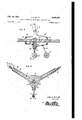
- Figure 1 is an end 'lev'ational view of the cutter
- Figure 2 is a si'r'nilar new showing the cutter in use
- Figure 3 is an enlarged view in elevation of one of the guide rollers and mounting therefor;
- Figure 4 is a similar view of the rotatable cutter and mounting therefor;
- Figure 5 is a longitudinal sectional view
- Figure 6 is a transverse sectional View taken substantially on a line 6-6 of Figure 5.
- the numeral 5 designates a flat substantially triangular shaped body having a pair of hollow arms 6 projecting from two of the corners of the body and a relatively short hollow arm I projecting from the third corner of the body,
- the outer portions of the wheel mountings 9 and lo are reduced in diameter to provide a shoulder l9 against which the inner end of a coil spring 20 is positioned, the spring being held under tension in the hollow arm by a hollow plug 2! threaded in the outer endnof the arm and through which the wheel: mounting isslidable.
- the ends of thefeed screw 22 project outwardly from the opposite sides of the body 5 and are smooth for sliding movement in front and rear guides 23 and '24 supported respectively forwardly and reartvardly of the body 5 by brackets 25 and 26.
- a guide roller 2'! is supported under the bracket 25 by 'a downwardly extending arm 28.
- a group of paper drying rollers or cylinders is designated at 29, 30 and 3
- the springs 20 retract the wheel mountings; 9 and Ill and the feed screw 22 projects the wheel mountings to adjust the guide rollers l4 and cutter 18 into an effective cutting position.
- the guide rollers l4 and cutter l8 may be interchangeably mounted on the wheel mountings 9 and H] to position the cutter for cutting the paper from either of the drying rollers 29. 301
- a paper cutter comprising a body having a plurality of hollow arms projecting radially therefrom, a wheel mounting slidable in each arm, means Working in the body at the inner ends of the mountings for projecting the mountings, spring means retracting the mountings, and wheels 'journalled at the outer ends of the mountings and adapted to travel longitudinally of and with the body centered between 'a group of triangularly arranged paper drying rollers, at .least one of the wheels constituting a cutter.
- a paper cutter comprising a carriage adapted to travel longitudinally between a group of triangularly arranged paper drying rollers, said carriage including a plurality of arms projecting radially from the longitudinal axis of the carriage, a cutter carried at the outer end of at least one of the arms for cuttingpaper from one of the rollers, wheels mounted atthe outer ends of the remaining arms to travel along the surface of the remaining rollers: to center the carriage between the rollers and a handle on the carriage to move the carriage back and forth along the 4.
- a paper cutter comprising a manually manipulated carriage adapted to travel longitudinal- 1y between a group of triangularly arranged paper drying rollers, said carriage including a plurality of arms projecting radially from the longitudinal axis of the carriage, a rotary cutter mounted at the outer end of at least one of the arms for cutting paper from one of the rollers, and wheels mounted at the outer ends of the remaining arms to travel along the surface of the remaining rollers to center the carriage between the rollers.
- a paper cutter comprising a manually manipulated carriage adapted to travel longitudinally between a group of triangularly arranged paper drying rollers, said carriage including a plurality of arms projecting radially from the longitudinal axis of the carriage, a rotary cutter mounted at the outerend of at least one of the arms for cutting paper from one of the rollers, wheels mounted at the outer ends of the remaining arms totravel along the surface of the remaining rollers to center the carriage between the rollers, and means carried by the carriage for radially adjusting the cutter and wheels on the arms.
Landscapes
- Paper (AREA)
Description
Feb. 24, 1953 J. c. NIX. 111
PAPER CUTTER FOR PAPER MILL DRYING ROLLERS 2 SHEETS-SHEET 1 Filed Feb. 4, 1948 John 6. Nix, 1Z7
INVENTOR.
Attorneys Feb. 24, 1953 J. c. NIX,I[[ 2,629,182
' PAPER CUTTER FOR PAPER MILL DRYING ROLLERS Filed Feb. 4, 1948 2 SHEETS-SHEET 2 Fig. 5
John 6. Nix,ZZZ
/8 l6 INVENTOR.
BY a, WQ FM Patented Feb. 24, 1953 UNITED STATES PATENT OFFICE PAPEROUTTER; FOR PAPER Mm. DRYING ROLLERS John "c. Nix, III, Tuscaloosa, Ala. Application February 4, 1948, Serial No. 6,327 9 dinin (or. 3445) The present invention relates to new and useful improvements in paper cutters and-more particularly to paper'cutters for use in cutting broken or torn paper from the drying rollers 'of paper mills.
Durin the manufacture of paper in paper mills the paper is run over a series of driers or rollers for the purpose of drying the paper. When the continuous paper sheet is broken or tom the loose paper generally wraps itself around one or more of the rollers or driers and must be removed before the paper is again fed to the rollers.
The drying rollers or cylinders are usually mounted in a triangular arrangement and not always accessible for removing the broken or torn paper therefrom. Accordingly it is an object of the present invention to provide a paper cutter which may be moved longitudinally between the rollers and embodying a rotatable cutter which may be positioned to travel longitudinally along any one of the rollers to cut the paper therefrom to facilitate removal of the torn paper. I
A further object of the invention is to provide a device of this character of "simple and practical construction, which is efficient and reliable in operation, relatively inexpensive to manufacture and otherwise well adapted for the purposes for which the same isintended. A
e Other objects and advantages reside in the details of constructionand operation as more fully hereinafter described and claimed, reference being had to the accompanying drawings forming part hereof, wherein like numerals refer to like parts throughout, andin which: i v
Figure 1 is an end 'lev'ational view of the cutter; A H
Figure 2 is a si'r'nilar new showing the cutter in use;
Figure 3 is an enlarged view in elevation of one of the guide rollers and mounting therefor;
Figure 4 is a similar view of the rotatable cutter and mounting therefor;
Figure 5 is a longitudinal sectional view, and
Figure 6 is a transverse sectional View taken substantially on a line 6-6 of Figure 5.
Referring now to the drawings in detail wherein for the purpose of illustration I have disclosed a preferred embodiment of the invention the numeral 5 designates a flat substantially triangular shaped body having a pair of hollow arms 6 projecting from two of the corners of the body and a relatively short hollow arm I projecting from the third corner of the body,
the arms extending radially from an opening 8 .plunger It) also forming awheel mounting. The
outer ends of the plungers Bare bifurcated as shown at ll and provided with transverse pinsl2 removably secured in position by cotter keys or the like I 3 'and on whichaguide roller I4 is journalled. The outer endof the wheel mounting Ill is likewise bifurcated as shown at I5 and provided with a transverse pin I6 removably secured inposition by cotter keysll and on which a rotatable cutter I8 is joumalled, The inner ends of theplungers areformed with threads 93.
The outer portions of the wheel mountings 9 and lo are reduced in diameter to provide a shoulder l9 against which the inner end of a coil spring 20 is positioned, the spring being held under tension in the hollow arm by a hollow plug 2! threaded in the outer endnof the arm and through which the wheel: mounting isslidable.
The inner ends of the wheel mountings 9 and lll'project into the central opening 8 inthe body for engagement by a tapered feed screw 22 slidable in the opening.
The ends of thefeed screw 22 project outwardly from the opposite sides of the body 5 and are smooth for sliding movement in front and rear guides 23 and '24 supported respectively forwardly and reartvardly of the body 5 by brackets 25 and 26.
A guide roller 2'! is supported under the bracket 25 by 'a downwardly extending arm 28.
In the operation of the device a group of paper drying rollers or cylinders is designated at 29, 30 and 3|, the cylinder or roller 29 being positioned under the cylinders or rollers 30 and 3% as shown in Figure? ofthedrarwings.
U The paper cutter'is "moved longitudinally betweenthe rollers 29, 3B and 3| with the guide rollers l4 carried by two of the arms 6 or I traveling along two of the drying rollers and the rotating cutter l8 traveling along the third drying roller to cut the paper therefrom.
The springs 20 retract the wheel mountings; 9 and Ill and the feed screw 22 projects the wheel mountings to adjust the guide rollers l4 and cutter 18 into an effective cutting position.
The guide rollers l4 and cutter l8 may be interchangeably mounted on the wheel mountings 9 and H] to position the cutter for cutting the paper from either of the drying rollers 29. 301
rollers.
In view of the foregoing description taken in conjunction with the accompanying drawings it is believed that a clear understanding of they construction, operation and advantages of the device will be quite apparent to those skilled in this art. A more detailed description is accordingly deemed unnecessary.
It is to be understood, however, that even though there is herein shown and described a. preferred embodiment of the invention the same is susceptible to certain changes fully compre- V hended by the spirit of the invention as herein invention, what is rollers, spring means retracting the-mountings,
and wheels journalled at the outer ends of the mountings, at least one-of the wheels constituting a cutter. v
2. A paper cutter comprising a body having a plurality of hollow arms projecting radially therefrom, a wheel mounting slidable in each arm, means Working in the body at the inner ends of the mountings for projecting the mountings, spring means retracting the mountings, and wheels 'journalled at the outer ends of the mountings and adapted to travel longitudinally of and with the body centered between 'a group of triangularly arranged paper drying rollers, at .least one of the wheels constituting a cutter.
3. A paper cuttercomprising a carriage adapted to travel longitudinally between a group of triangularly arranged paper drying rollers, said carriage including a plurality of arms projecting radially from the longitudinal axis of the carriage, a cutter carried at the outer end of at least one of the arms for cuttingpaper from one of the rollers, wheels mounted atthe outer ends of the remaining arms to travel along the surface of the remaining rollers: to center the carriage between the rollers and a handle on the carriage to move the carriage back and forth along the 4. A paper cutter comprising a manually manipulated carriage adapted to travel longitudinal- 1y between a group of triangularly arranged paper drying rollers, said carriage including a plurality of arms projecting radially from the longitudinal axis of the carriage, a rotary cutter mounted at the outer end of at least one of the arms for cutting paper from one of the rollers, and wheels mounted at the outer ends of the remaining arms to travel along the surface of the remaining rollers to center the carriage between the rollers.
5. A paper cutter comprising a manually manipulated carriage adapted to travel longitudinally between a group of triangularly arranged paper drying rollers, said carriage including a plurality of arms projecting radially from the longitudinal axis of the carriage, a rotary cutter mounted at the outerend of at least one of the arms for cutting paper from one of the rollers, wheels mounted at the outer ends of the remaining arms totravel along the surface of the remaining rollers to center the carriage between the rollers, and means carried by the carriage for radially adjusting the cutter and wheels on the arms.
6-. The combination of claim 4, wherein salt arms are tubular, and mountings for the cutter and wheels slidably carried by the arms.
7. The combination of claim 4, wherein said arms are tubular, mountings for the cutter and wheels slidably carried by the arms, spring means retracting the mountings, and means carried by the carriage projecting the mountings to hold the cutter and wheels in contact with the rollers.
8. The combination of claim 4, wherein said arms are tubular, mountings for the cutter and wheels slidably carried by the arms, spring means retracting the mountings, and a tapered member movable longitudinally in the carriageand engaging the inner ends of the mountings to project the cutter and wheels into contact with th rollers.
9. The combination of claim 4, wherein said arms are tubular, mountings for the cutter'and wheels slidably carried by the arms, spring means retracting the mountings, and a tapered feed screw working in the carriage and engaging the inner ends of the mountings to project the cutter and wheels into contact with the rollers.
JOHN C. NIX, III.
REFERENCES CITED UNITED STATES PATENTS Number Name Date a 67,601 Stephen Aug. 6, 1867 116,136 Aguayo June 20, 1871 588,477 Robards Aug. 17, 1897 772,062 Roush Oct.'11, 1904 821,816 Myrick May 29, 1906 837,426 Seymour Dec. 4, 1906 837,614 Dierzen Dec. 4, 1906 890,795 Putsch June 16, 1908 957,219 Kukkuck May 10, 1910 1,344,173 Carrier June 22, 1920 1,549,791 North Aug. 18, 1925 1,665,644 Sponsel Apr. 10, 1928 2,506,366 Korn May 2, 1950 FOREIGN PATENTS Number Country Date Germany Sept. 13, 1905
Priority Applications (1)
| Application Number | Priority Date | Filing Date | Title |
|---|---|---|---|
| US6327A US2629182A (en) | 1948-02-04 | 1948-02-04 | Paper cutter for paper mill drying rollers |
Applications Claiming Priority (1)
| Application Number | Priority Date | Filing Date | Title |
|---|---|---|---|
| US6327A US2629182A (en) | 1948-02-04 | 1948-02-04 | Paper cutter for paper mill drying rollers |
Publications (1)
| Publication Number | Publication Date |
|---|---|
| US2629182A true US2629182A (en) | 1953-02-24 |
Family
ID=21720354
Family Applications (1)
| Application Number | Title | Priority Date | Filing Date |
|---|---|---|---|
| US6327A Expired - Lifetime US2629182A (en) | 1948-02-04 | 1948-02-04 | Paper cutter for paper mill drying rollers |
Country Status (1)
| Country | Link |
|---|---|
| US (1) | US2629182A (en) |
Cited By (1)
| Publication number | Priority date | Publication date | Assignee | Title |
|---|---|---|---|---|
| US3392445A (en) * | 1965-10-24 | 1968-07-16 | Koran Julia | Combination swiveling and stationary glass cutting tool |
Citations (14)
| Publication number | Priority date | Publication date | Assignee | Title |
|---|---|---|---|---|
| DE162805C (en) * | ||||
| US67601A (en) * | 1867-08-06 | Improved pastry-cutter | ||
| US116136A (en) * | 1871-06-20 | Improvement in tobacco-cutters | ||
| US588477A (en) * | 1897-08-17 | Cutter for cigar-wrappers | ||
| US772062A (en) * | 1903-11-10 | 1904-10-11 | John J Roush | Tube-cutter. |
| US821816A (en) * | 1905-11-14 | 1906-05-29 | Thomas William Myrick | Pipe or tube cutter. |
| US837614A (en) * | 1906-03-24 | 1906-12-04 | Albert J Dierzen | Tube-cutter. |
| US837426A (en) * | 1905-10-23 | 1906-12-04 | George Frederick Seymour | Boiler-tube cutter. |
| US890795A (en) * | 1907-11-25 | 1908-06-16 | Fredrich W Putsch | Boiler tube or flue cutter. |
| US957219A (en) * | 1909-12-06 | 1910-05-10 | Frederick Kukkuck | Composition-leather machine. |
| US1344173A (en) * | 1919-04-05 | 1920-06-22 | Carrier Joseph Gildert | Pulp-machine |
| US1549791A (en) * | 1922-11-16 | 1925-08-18 | Ray A North | Pulp-roll skinner |
| US1665644A (en) * | 1927-06-14 | 1928-04-10 | Case & Marshall Inc | Cutting mechanism for pulp and like machines |
| US2506366A (en) * | 1945-02-12 | 1950-05-02 | Estol P Korn | Lawn edger |
-
1948
- 1948-02-04 US US6327A patent/US2629182A/en not_active Expired - Lifetime
Patent Citations (14)
| Publication number | Priority date | Publication date | Assignee | Title |
|---|---|---|---|---|
| US67601A (en) * | 1867-08-06 | Improved pastry-cutter | ||
| US116136A (en) * | 1871-06-20 | Improvement in tobacco-cutters | ||
| US588477A (en) * | 1897-08-17 | Cutter for cigar-wrappers | ||
| DE162805C (en) * | ||||
| US772062A (en) * | 1903-11-10 | 1904-10-11 | John J Roush | Tube-cutter. |
| US837426A (en) * | 1905-10-23 | 1906-12-04 | George Frederick Seymour | Boiler-tube cutter. |
| US821816A (en) * | 1905-11-14 | 1906-05-29 | Thomas William Myrick | Pipe or tube cutter. |
| US837614A (en) * | 1906-03-24 | 1906-12-04 | Albert J Dierzen | Tube-cutter. |
| US890795A (en) * | 1907-11-25 | 1908-06-16 | Fredrich W Putsch | Boiler tube or flue cutter. |
| US957219A (en) * | 1909-12-06 | 1910-05-10 | Frederick Kukkuck | Composition-leather machine. |
| US1344173A (en) * | 1919-04-05 | 1920-06-22 | Carrier Joseph Gildert | Pulp-machine |
| US1549791A (en) * | 1922-11-16 | 1925-08-18 | Ray A North | Pulp-roll skinner |
| US1665644A (en) * | 1927-06-14 | 1928-04-10 | Case & Marshall Inc | Cutting mechanism for pulp and like machines |
| US2506366A (en) * | 1945-02-12 | 1950-05-02 | Estol P Korn | Lawn edger |
Cited By (1)
| Publication number | Priority date | Publication date | Assignee | Title |
|---|---|---|---|---|
| US3392445A (en) * | 1965-10-24 | 1968-07-16 | Koran Julia | Combination swiveling and stationary glass cutting tool |
Similar Documents
| Publication | Publication Date | Title |
|---|---|---|
| GB1511785A (en) | Apparatus for aligning a longitudinal textile web and for severing it in a transverse direction | |
| US3041967A (en) | Cylinder support and moving means for printing mechanism | |
| US2712852A (en) | Cutter unit for slitting machines | |
| US2187211A (en) | Paper slitter | |
| US2629182A (en) | Paper cutter for paper mill drying rollers | |
| GB1449550A (en) | Self-centering roll holder | |
| US1242448A (en) | Cloth-cutting machine. | |
| US2143443A (en) | Bending machine | |
| US3328924A (en) | Apparatus for sharpening rotary cutters | |
| US2737237A (en) | Apparatus for slitting tires to a selected depth | |
| GB1137800A (en) | Cutting apparatus | |
| US2494196A (en) | Lathe | |
| GB1516026A (en) | Cutter for severing a strip or cord | |
| US2576239A (en) | Tube thread grinding machine | |
| US2696857A (en) | Portable electric contour shaping machine | |
| US2624407A (en) | Wallpaper trimming machine | |
| GB856192A (en) | Improvements in or relating to machines for perforating, slitting, creasing, and like operations on paper or the like | |
| US2117979A (en) | Grinding machine | |
| US2523643A (en) | Doctor blade mechanism for rotary intaglio printing machines | |
| US2995767A (en) | Roughening machine | |
| US2293886A (en) | Printing machine | |
| US3076249A (en) | Tubular fabric spreading and rolling machine | |
| GB248893A (en) | Improvements in machines for grinding pins, rollers, tubes and the like | |
| US2036241A (en) | Trimmer | |
| US1873423A (en) | Grinding machine |