US2617536A - Curtain hanging means - Google Patents
Curtain hanging means Download PDFInfo
- Publication number
- US2617536A US2617536A US204589A US20458951A US2617536A US 2617536 A US2617536 A US 2617536A US 204589 A US204589 A US 204589A US 20458951 A US20458951 A US 20458951A US 2617536 A US2617536 A US 2617536A
- Authority
- US
- United States
- Prior art keywords
- plates
- brackets
- rod
- curtain
- rods
- Prior art date
- Legal status (The legal status is an assumption and is not a legal conclusion. Google has not performed a legal analysis and makes no representation as to the accuracy of the status listed.)
- Expired - Lifetime
Links
- 230000005484 gravity Effects 0.000 description 1
- 239000000725 suspension Substances 0.000 description 1
Images

Classifications
-
- A—HUMAN NECESSITIES
- A47—FURNITURE; DOMESTIC ARTICLES OR APPLIANCES; COFFEE MILLS; SPICE MILLS; SUCTION CLEANERS IN GENERAL
- A47H—FURNISHINGS FOR WINDOWS OR DOORS
- A47H1/00—Curtain suspension devices
- A47H1/10—Means for mounting curtain rods or rails
- A47H1/13—Brackets or adjustable mountings for both roller blinds and drawable curtains
Definitions
- This invention relates to curtain hanging; means and has special reference to. means forsecuring-curtain rods to amovable support.
- bracket and plate combination which permits curtainsand the like to be put up or taken down. without the use of a ladder, or. the like;
- My present invention utilizes this bracket and plate structure, and has as its principal object the provision of novel means for mounting curtain rods on the said plates so that the same may be readily put up and taken down as desired.
- Another object is to provide means for securing telescopic curtain rods together to prevent their extension unintentionally.
- Another object is to provide means for mounting curtain rods on the said plates which are simple and efficient yet relatively inexpensive.
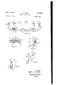
- Fig. 1 is a broken top plan view of one form of my curtain rod mounting means.
- Fig. 2 is a'broken perspective view of the device shown in Fig.1 showing the operation thereof.
- Fig. 3 is a side elevational view of the bracket and plate.
- Fig. 4 is'a perspective view of Fig. 3.
- Fig. 5 is a broken top plan view showing a modified form of curtain rod mounting means.
- Fig. 6 is a sectional view on the line 6-6, Fig. 5.
- Fig. 7 is a sectional view on the line 1-1, Fig. 6.
- Fig. 8 is a perspective view of a plate member showing another curtain rod mounting means.
- Fig. 9 is a broken side elevational view showing a curtain rod in place on the plate shown in Fig. 8.
- the reference numeral I indicates the window frame on which the brackets 2-2 are mounted in spaced horizontally alined relationship.
- the brackets 2-2 project in vertical relationship from the frame i and have a substantially V-shaped hook portion 3 at the lower outer end thereof, the outermost edge of the hook 3 forming an upwardly inclined guide 4 for the plates 5 as they are raised to insure proper seating of the plates on the brackets, as will become apparent.
- the upper outer end of the bracket is inclined inwardly as at 6.
- the plates 5 are shaped to the contour of the outer edge of the brackets 2,-as: shown, having an upper, inwardly inclined portion 1. to rest against the edge 6; a straight portion 8 Which extends in parallel relation with the window frame, and a lower'angularportion made upof two oppositely inclined walls" 9 and lll' which form a hookto engage on the' cooperative hooking member 3, asshown.
- Each of theplates is pro-- vided' with" means, suchas-theholes I I, to which the cords l'2-l2 may be attached for raisingthe plates toand from the brackets 2; the cords l2 being rovethrough suitable eyes-l3andl4 onthe bracketsso thatth'e ends of the cords I Zmay bebrought down along the window frame to" within easy reach of a person standing'on the floor near the window. Any suitable eye, not shown, or similar device may be secured to the lower portion of the window frame to provide means to-tie, the cords IZandholdl the plates 5in place Inoperation, curtains, not shown, are carried. on a curtain rodjiiiv adjacent the upper endof.
- asecondrod I5 is. provided to carry a valance. or the like.
- the second rod I5 is secured to the rod 3i by any common curtain rod hanging bracket I 6 which extends therebetween.
- each of the plates 5 is provided with an L-shaped member H which extends rearwardly from the outer vertical edge of the plate, as shown, the leg portion of the L-shaped member having the bracket I6 secured thereto with suitable spaced lugs l8 to receive the ends of the curtain rods in the conventional manner.
- a modified means to mount the curtain rods on the plates The rods 3 land are held in their desired spaced relation by the common rod bracket 16; however, the rod 3! is secured directly to the plates by means of a nut or nuts 19 which are installed on a threaded shank or shanks 20.
- the shanks 20 are the legs of a U-shaped holding fram 2
- the plate is of a width to span the usual opening 23 which is present in the rear face of common curtain rods, as s shown.
- the plates 5 are provided with openings 24 through which the legs 20 extend, the nuts 19 being carried on the rear face of the plates, as shown.
- curtains are installed on the rods 3
- Figs. 8 and 9 I have shown a further modified form of means for mounting the curtain rods on the plate 5.
- a third lug 21 is struck forwardly from the body of the plate 5 and extends substantially normal to the surface of the plate; however, the lower edge of the lug 21 is preferably inclined upwardly slightly, as at 28, so that the lower edge 29 of the curtain rod may be engaged thereby to form a firm mounting for the rod on the plates.
- the two parts of the rod 31 which telescope together means of a clamping device to prevent their moving laterally accidentally.
- Means for supporting curtains and the like on a window frame comprising: a rod adapted to carry said curtains, a pair of brackets secured to said frame in spaced alined relation, a pair of plates, means securing said plates to said rod to correspond with said brackets, and a cord secured to each of said plates and slidably carried by said brackets for lowering said plates and rod from said brackets and raising same to said brackets, said means comprising a pair of hook-shaped members struck from and extending outwardly and upwardly from said plates, said hooks being in horizontal alined relationship, and said rod having a rolled upper edge into which said hooks are engaged.
- Means for supporting curtains and the like on a window frame comprising: a rod adapted to carry said curtains, a pair of brackets secured to said frame in spaced alined relation, a pair of plates, means securing said plates to said rod to correspond with said brackets, and a cord secured to each of said plates and slidably carried by said brackets for lowering said plates and rod from said brackets and raising same to said brackets, said means comprising a pair of hook-shaped members struck from and extending outwardly and upwardly from said plates, said hook being in horizontal alined relationship, said rod having a rolled upper edge into which said hooks are engaged and a lug pressed outwardly from said plates below said hooks, said lug having an edge inclined upwardly slightly to engage and frictionally hold the lower portion of said rod in place.
Landscapes
- Curtains And Furnishings For Windows Or Doors (AREA)
Description
Nov. .11, 1952.. c. w. HESS 2,617,536
CURTAIN HANGING MEANS Filed Jan. 5, 1951 2 SHEETS-SHEET l INVENTOR.
CARL W HESS [FM/PW AGENT Nov. 11, 1952 c. w. HESS 2,617,536
CURTAIN HANGING MEANS Filed Jan. 5, 1951 2 SHEETS--SHEET 2 FIG. 7
INVENTOR.
0 m w. HESS AGENT Patented Nov. 11, 1952 CURTAINHANGING MEANS Carl W. Hess, Superior, Wis.. Application January 5, 1951,"Serial'No. 204,589.
2 Claims. (Cl. 211,-+103;)L
This invention relates to curtain hanging; means and has special reference to. means forsecuring-curtain rods to amovable support.
In my co-pending application forv patent, Serial Number 106,589, filed July 25, 1949, whichv matured into U.v S. Patent 2,568,498 on September-18, 1951, I have shown and described a particular: bracket and plate combination which permits curtainsand the like to be put up or taken down. without the use of a ladder, or. the like; My present invention utilizes this bracket and plate structure, and has as its principal object the provision of novel means for mounting curtain rods on the said plates so that the same may be readily put up and taken down as desired.
Another object is to provide means for securing telescopic curtain rods together to prevent their extension unintentionally.
Another object is to provide means for mounting curtain rods on the said plates which are simple and efficient yet relatively inexpensive.
Other objects and advantages will become more apparent as the description of the invention proceeds- In the accompanying drawing forming a part of this application:
Fig. 1 is a broken top plan view of one form of my curtain rod mounting means.
Fig. 2 is a'broken perspective view of the device shown in Fig.1 showing the operation thereof.
Fig. 3 is a side elevational view of the bracket and plate.
Fig. 4 is'a perspective view of Fig. 3.
Fig. 5 is a broken top plan view showing a modified form of curtain rod mounting means.
Fig. 6 is a sectional view on the line 6-6, Fig. 5.
Fig. 7 is a sectional view on the line 1-1, Fig. 6.
Fig. 8 is a perspective view of a plate member showing another curtain rod mounting means.
Fig. 9 is a broken side elevational view showing a curtain rod in place on the plate shown in Fig. 8.
In the drawing the reference numeral I indicates the window frame on which the brackets 2-2 are mounted in spaced horizontally alined relationship. The brackets 2-2 project in vertical relationship from the frame i and have a substantially V-shaped hook portion 3 at the lower outer end thereof, the outermost edge of the hook 3 forming an upwardly inclined guide 4 for the plates 5 as they are raised to insure proper seating of the plates on the brackets, as will become apparent.
The upper outer end of the bracket is inclined inwardly as at 6.
The plates 5 are shaped to the contour of the outer edge of the brackets 2,-as: shown, having an upper, inwardly inclined portion 1. to rest against the edge 6; a straight portion 8 Which extends in parallel relation with the window frame, and a lower'angularportion made upof two oppositely inclined walls" 9 and lll' which form a hookto engage on the' cooperative hooking member 3, asshown. Each of theplates is pro-- vided' with" means, suchas-theholes I I, to which the cords l'2-l2 may be attached for raisingthe plates toand from the brackets 2; the cords l2 being rovethrough suitable eyes-l3andl4 onthe bracketsso thatth'e ends of the cords I Zmay bebrought down along the window frame to" within easy reach of a person standing'on the floor near the window. Any suitable eye, not shown, or similar device may be secured to the lower portion of the window frame to provide means to-tie, the cords IZandholdl the plates 5in place Inoperation, curtains, not shown, are carried. on a curtain rodjiiiv adjacent the upper endof. the window frame, and at times,. asecondrod I5 is. provided to carry a valance. or the like. The second rod I5 is secured to the rod 3i by any common curtain rod hanging bracket I 6 which extends therebetween. The common mounting for; these rods 31 and l5-comprises. securing the brackets [-6 tothe window frame.
My invention; utilizes the above described.
brackets! andpiatesr'5, howevento permit. the
rodsqto-be raised into place-or'lowered; without a ladder or the like. The rods aresecured to the. plates 5 by various means. In Figs. 14, each of the plates 5 is provided with an L-shaped member H which extends rearwardly from the outer vertical edge of the plate, as shown, the leg portion of the L-shaped member having the bracket I6 secured thereto with suitable spaced lugs l8 to receive the ends of the curtain rods in the conventional manner.
This arrangement puts the ends of the curtain rods relatively close to the window frame, as shown, yet keeps the point of suspension of the curtain rods and plates relatively close to the center of gravity, thereby insuring that the plates 5 will be carried in substantially vertical position as they are raised and lowered, and thereby insuring that the plates will engage properly on the brackets as they reach same; that is, the V- shaped hook 9|0 will catch on the cooperative hook member 3 of the bracket to stop same exactly in place. It is to be noted that the inwardly inclined upper edge I of the plates 5 is held against the similarly inclined edge 6 of the brackets 2 by the cords l2-l2 when the plates are in uppermost position and the cords held tight. By this arrangement, a great proportion of the weight of the rods and curtains is supported by the brackets rather than by the cords l2, which merely have to hold the plates against the brackets, as shown.
In Figs. 5, 6, and 7, I have shown a modified means to mount the curtain rods on the plates. The rods 3 land are held in their desired spaced relation by the common rod bracket 16; however, the rod 3! is secured directly to the plates by means of a nut or nuts 19 which are installed on a threaded shank or shanks 20. As shown, the shanks 20 are the legs of a U-shaped holding fram 2| which is mounted in the rod 3|, a plate 22 being provided with holes through which the legs 20 of the frame extend. The plate is of a width to span the usual opening 23 which is present in the rear face of common curtain rods, as s shown. The plates 5 are provided with openings 24 through which the legs 20 extend, the nuts 19 being carried on the rear face of the plates, as shown. Of course, curtains are installed on the rods 3| and I5 before the legs 20 are inserted through the openings 24 in the plates.
The rods and plates are lowered and raised in the same manner as above, of course. In Figs. 8 and 9, I have shown a further modified form of means for mounting the curtain rods on the plate 5. There are a pair of pointed lugs 25 stamped or pressed forwardly from the body of the plate as shown, the lugs being bent to form a hook which extends outwardly and upwardly so that the upper rolled edge 26- of the curtain rod 3i may be engaged on the hook 25 as seen in Fig. 9.
A third lug 21 is struck forwardly from the body of the plate 5 and extends substantially normal to the surface of the plate; however, the lower edge of the lug 21 is preferably inclined upwardly slightly, as at 28, so that the lower edge 29 of the curtain rod may be engaged thereby to form a firm mounting for the rod on the plates.
It is preferred that the two parts of the rod 31 which telescope together means of a clamping device to prevent their moving laterally accidentally.
It is deemed apparent, from the above, that I have developed a new and useful curtain hanging means which is relatively simple to operate and which will aid materially in lessening home accidents which occur when persons use improper ladders or the like.
be clamped in place by .3.
Having thus described my invention, what I claim is:
1. Means for supporting curtains and the like on a window frame comprising: a rod adapted to carry said curtains, a pair of brackets secured to said frame in spaced alined relation, a pair of plates, means securing said plates to said rod to correspond with said brackets, and a cord secured to each of said plates and slidably carried by said brackets for lowering said plates and rod from said brackets and raising same to said brackets, said means comprising a pair of hook-shaped members struck from and extending outwardly and upwardly from said plates, said hooks being in horizontal alined relationship, and said rod having a rolled upper edge into which said hooks are engaged.
2. Means for supporting curtains and the like on a window frame comprising: a rod adapted to carry said curtains, a pair of brackets secured to said frame in spaced alined relation, a pair of plates, means securing said plates to said rod to correspond with said brackets, and a cord secured to each of said plates and slidably carried by said brackets for lowering said plates and rod from said brackets and raising same to said brackets, said means comprising a pair of hook-shaped members struck from and extending outwardly and upwardly from said plates, said hook being in horizontal alined relationship, said rod having a rolled upper edge into which said hooks are engaged and a lug pressed outwardly from said plates below said hooks, said lug having an edge inclined upwardly slightly to engage and frictionally hold the lower portion of said rod in place.
CARL W. HESS.
REFERENCES CITED The following references are of record in the file of this patent:
UNITED STATES PATENTS
Priority Applications (1)
| Application Number | Priority Date | Filing Date | Title |
|---|---|---|---|
| US204589A US2617536A (en) | 1951-01-05 | 1951-01-05 | Curtain hanging means |
Applications Claiming Priority (1)
| Application Number | Priority Date | Filing Date | Title |
|---|---|---|---|
| US204589A US2617536A (en) | 1951-01-05 | 1951-01-05 | Curtain hanging means |
Publications (1)
| Publication Number | Publication Date |
|---|---|
| US2617536A true US2617536A (en) | 1952-11-11 |
Family
ID=22758554
Family Applications (1)
| Application Number | Title | Priority Date | Filing Date |
|---|---|---|---|
| US204589A Expired - Lifetime US2617536A (en) | 1951-01-05 | 1951-01-05 | Curtain hanging means |
Country Status (1)
| Country | Link |
|---|---|
| US (1) | US2617536A (en) |
Cited By (1)
| Publication number | Priority date | Publication date | Assignee | Title |
|---|---|---|---|---|
| US20080230314A1 (en) * | 2007-03-21 | 2008-09-25 | Svehlek John R | Ladder Security Bracket and Safety System |
Citations (7)
| Publication number | Priority date | Publication date | Assignee | Title |
|---|---|---|---|---|
| GB191012123A (en) * | 1909-05-18 | Wollak Victor | An Improved Device for Raising, Securing and Lowering Curtains. | |
| US1743608A (en) * | 1928-05-14 | 1930-01-14 | Kenney Mfg Co | Curtain fixture |
| US2026388A (en) * | 1934-09-22 | 1935-12-31 | Jenal Matthew | Device to raise and lower curtains and drapes |
| US2229898A (en) * | 1940-06-15 | 1941-01-28 | Pastva George | Regulator for curtains and blinds |
| US2374605A (en) * | 1943-03-11 | 1945-04-24 | Lundstrom Ida | Curtain fixture |
| US2461417A (en) * | 1949-02-08 | Curtain support | ||
| US2568498A (en) * | 1949-07-25 | 1951-09-18 | Carl W Hess | Curtain hanging means |
-
1951
- 1951-01-05 US US204589A patent/US2617536A/en not_active Expired - Lifetime
Patent Citations (7)
| Publication number | Priority date | Publication date | Assignee | Title |
|---|---|---|---|---|
| US2461417A (en) * | 1949-02-08 | Curtain support | ||
| GB191012123A (en) * | 1909-05-18 | Wollak Victor | An Improved Device for Raising, Securing and Lowering Curtains. | |
| US1743608A (en) * | 1928-05-14 | 1930-01-14 | Kenney Mfg Co | Curtain fixture |
| US2026388A (en) * | 1934-09-22 | 1935-12-31 | Jenal Matthew | Device to raise and lower curtains and drapes |
| US2229898A (en) * | 1940-06-15 | 1941-01-28 | Pastva George | Regulator for curtains and blinds |
| US2374605A (en) * | 1943-03-11 | 1945-04-24 | Lundstrom Ida | Curtain fixture |
| US2568498A (en) * | 1949-07-25 | 1951-09-18 | Carl W Hess | Curtain hanging means |
Cited By (2)
| Publication number | Priority date | Publication date | Assignee | Title |
|---|---|---|---|---|
| US20080230314A1 (en) * | 2007-03-21 | 2008-09-25 | Svehlek John R | Ladder Security Bracket and Safety System |
| US9551182B2 (en) * | 2007-03-21 | 2017-01-24 | John R. Svehlek | Ladder security bracket and safety system |
Similar Documents
| Publication | Publication Date | Title |
|---|---|---|
| US2528358A (en) | Rod support | |
| US1751691A (en) | Bracket | |
| US2192070A (en) | Seat cover | |
| US2678243A (en) | Portable scaffolding | |
| US2251512A (en) | Curtain tieback bracket | |
| US1924074A (en) | Support for curtains and other light articles | |
| US2458643A (en) | Bracket for drapery fixtures | |
| US2617536A (en) | Curtain hanging means | |
| US1424337A (en) | Curtain fixture | |
| US2056874A (en) | Curtain fixture | |
| US1876111A (en) | Child's vehicle with reclining back | |
| US4218793A (en) | Mounting assembly for bunk bed ladder or the like | |
| US2112206A (en) | Support for window shade rollers | |
| US2205935A (en) | Leveling attachment for ladders | |
| US2534491A (en) | Drapery fixture | |
| US2364521A (en) | Ladder supporting means | |
| US2565280A (en) | Curtain rod hanger | |
| US2738154A (en) | Hanger | |
| US2500423A (en) | Collapsible coat hanger | |
| US2549448A (en) | Drape rod supporting means | |
| US2568498A (en) | Curtain hanging means | |
| US2201887A (en) | Awning structure | |
| US1381606A (en) | Curtain and shade bracket | |
| US2658556A (en) | Child's seat | |
| US2492867A (en) | Window suspension means for venetian blinds |