US2503534A - Liquid fuel injection means for internal-combustion engines - Google Patents
Liquid fuel injection means for internal-combustion engines Download PDFInfo
- Publication number
- US2503534A US2503534A US747069A US74706947A US2503534A US 2503534 A US2503534 A US 2503534A US 747069 A US747069 A US 747069A US 74706947 A US74706947 A US 74706947A US 2503534 A US2503534 A US 2503534A
- Authority
- US
- United States
- Prior art keywords
- liquid fuel
- nozzle
- fuel injection
- injection means
- internal
- Prior art date
- Legal status (The legal status is an assumption and is not a legal conclusion. Google has not performed a legal analysis and makes no representation as to the accuracy of the status listed.)
- Expired - Lifetime
Links
- 239000000446 fuel Substances 0.000 title description 19
- 239000007788 liquid Substances 0.000 title description 13
- 238000002485 combustion reaction Methods 0.000 title description 8
- 238000002347 injection Methods 0.000 title description 4
- 239000007924 injection Substances 0.000 title description 4
- 230000006698 induction Effects 0.000 description 5
- 241001061260 Emmelichthys struhsakeri Species 0.000 description 1
- 230000002950 deficient Effects 0.000 description 1
- 238000000151 deposition Methods 0.000 description 1
- 230000000694 effects Effects 0.000 description 1
- 238000000605 extraction Methods 0.000 description 1
- 239000002184 metal Substances 0.000 description 1
- 239000002245 particle Substances 0.000 description 1
- 239000007787 solid Substances 0.000 description 1
Images
Classifications
-
- F—MECHANICAL ENGINEERING; LIGHTING; HEATING; WEAPONS; BLASTING
- F02—COMBUSTION ENGINES; HOT-GAS OR COMBUSTION-PRODUCT ENGINE PLANTS
- F02M—SUPPLYING COMBUSTION ENGINES IN GENERAL WITH COMBUSTIBLE MIXTURES OR CONSTITUENTS THEREOF
- F02M61/00—Fuel-injectors not provided for in groups F02M39/00 - F02M57/00 or F02M67/00
- F02M61/04—Fuel-injectors not provided for in groups F02M39/00 - F02M57/00 or F02M67/00 having valves, e.g. having a plurality of valves in series
- F02M61/08—Fuel-injectors not provided for in groups F02M39/00 - F02M57/00 or F02M67/00 having valves, e.g. having a plurality of valves in series the valves opening in direction of fuel flow
-
- F—MECHANICAL ENGINEERING; LIGHTING; HEATING; WEAPONS; BLASTING
- F02—COMBUSTION ENGINES; HOT-GAS OR COMBUSTION-PRODUCT ENGINE PLANTS
- F02M—SUPPLYING COMBUSTION ENGINES IN GENERAL WITH COMBUSTIBLE MIXTURES OR CONSTITUENTS THEREOF
- F02M2700/00—Supplying, feeding or preparing air, fuel, fuel air mixtures or auxiliary fluids for a combustion engine; Use of exhaust gas; Compressors for piston engines
- F02M2700/07—Nozzles and injectors with controllable fuel supply
Definitions
- partial vacuum in the induction pipe, (or in the cylinder or cylinders) causes undesired fuel flow through the improperly closed nozzle or nozzles, with consequent defective running of the engine and wastage of fuel, especially at idling speeds.
- the object of the present invention is to enable the undesirable condition above mentioned to be avoided in a convenient and satisfactory manner.
- the invention comprises the combination with the liquid fuel delivery nozzle, or each such nomle,
- the drawing indicates a nozzle, or one of a plurality of nozzles, through which measured quantities of petrol or other like liquid fuel can be injected by a pump into the induction pipe or cylinder of an internal combustion engine.
- the nozzle a is provided at its front end with a liquid fueldischarge orifice b, and contains a springloaded closure member past which the liquid fuel to flow to the discharge orifice.
- the nozzle a is enclosed by; a sleeve d forming an air or other gas chamber around and at the front end of the nozzle, the sleeve being formed at its front end with a constantly open discharge orifice or orifices as e.
- the interior of the sleeve d is kept at all times filled with air or other gas (which may be engine exhaust gas) at a pressure which is independent of the air required for combustion of the 2 fuel delivered by the nozzle a, and which is sufllciently in excess of the lowest pressure which may exist in the engine induction pipe or cylinder (as when the throttle valve is fully closed) to prevent the extraction of liquid fuel through the fuel nozzle by suction, in the event of the nozzle closure member c being imperfectly closed.
- air or other gas which may be engine exhaust gas
- the desired preponderance of pressure in the interior of the sleeve d may be obtained by suitably dimensioning its volume and/or its discharge orifice or orifices as e, in which case the rear end of the sleeve may be in free communication with the outer atmosphere.
- the pressure of this gas may be sufilcient to serve the desired purpose.
- a small air or other gas compressor or blower adapted to maintain the desired pressure in the sleeve d.
- the rear end of the sleeve :1 may be accured to a hollow fitting I having a laterally arranged inlet Opening a for the air or other gas. It will be understood, however, that the amount of air or other gas which can pass from the interior of the sleeve d to the induction pipe or cylinder is not sufilcient materially to affect the normal action of the engine.
- the invention is not, however, limited to the example described as the form of the nozzle and sleeve may be varied to suit requirements.
- Liquid fuel injection means for an internal combustion engine comprising the combination with a liquid fuel delivery nozzle having an outlet at one end, of a gas chamber situated around and enclosing the nozzle outlet, and having at least one constantly open discharge orifice spaced from and at the outer side of the nozzle outlet, and means for maintaining at all times in the said chamber a gas pressure which is independent of the air required for combustion of the fuel delivered by the nozzle, and which is sufficiently in excess of the engine intake pressure to prevent fuel from being drawn through the nozzle outlet.
Landscapes
- Engineering & Computer Science (AREA)
- Chemical & Material Sciences (AREA)
- Combustion & Propulsion (AREA)
- Mechanical Engineering (AREA)
- General Engineering & Computer Science (AREA)
- Fuel-Injection Apparatus (AREA)
Description
Patented Apr. 11, 1950 LIQUID FUEL INJECTION MEANS FOR INTERNAL-COMBUSTION ENGINES Maurice Carey Wilks, Solihull, England, assignmlan to Rover Company Limited, Solihull, Eng- Application May 9, 1947, Serial No. 747,089 In Great Britain August 21, 1944 1 Claim. (Cl. 299-1071) This invention relates to liquid fuel injection means of the kind comprising a nozzle or nozzles through which measured quantities of petrol or other like liquid fuel are injected by a Pump into the induction pipe or cylinder or cylinders of an internal combustion engine. Ordinarily the orifice of the nozzle is controlled by a spring-loaded closure member, and both the closure member and its seating are made from metal. Difficulty has been found in ensuring proper closing of the said member on its seating owing to the depositing of minute solid particles thereon or on the seating from the liquid or other source. A result of this condition is that when the engine is running with the throttle valve closed or nearly closed, the
partial vacuum in the induction pipe, (or in the cylinder or cylinders) causes undesired fuel flow through the improperly closed nozzle or nozzles, with consequent defective running of the engine and wastage of fuel, especially at idling speeds.
The object of the present invention is to enable the undesirable condition above mentioned to be avoided in a convenient and satisfactory manner. 7 The invention comprises the combination with the liquid fuel delivery nozzle, or each such nomle,
- of an air or other gas chamber situated around and enclosing the nozzle outlet, and having a constantly open discharge orifice or orifices spaced from and in advance of the nozzle outlet, and meansfor maintaining at all times in the said chamber an air or other gas pressure which is independent of the air required for combustion of the fuel delivered by the nozzle, and which is sufficiently in excess of the engine intake pressure to prevent fuel from being drawn through the nozzle outlet.
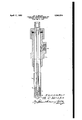
"The accompanying drawing is a sectional side elevation of liquid fuel injecting means embodying the invention.
In the drawing it indicates a nozzle, or one of a plurality of nozzles, through which measured quantities of petrol or other like liquid fuel can be injected by a pump into the induction pipe or cylinder of an internal combustion engine. The nozzle a is provided at its front end with a liquid fueldischarge orifice b, and contains a springloaded closure member past which the liquid fuel to flow to the discharge orifice. In carrying the invention into effect as shown, the nozzle a is enclosed by; a sleeve d forming an air or other gas chamber around and at the front end of the nozzle, the sleeve being formed at its front end with a constantly open discharge orifice or orifices as e. The interior of the sleeve d is kept at all times filled with air or other gas (which may be engine exhaust gas) at a pressure which is independent of the air required for combustion of the 2 fuel delivered by the nozzle a, and which is sufllciently in excess of the lowest pressure which may exist in the engine induction pipe or cylinder (as when the throttle valve is fully closed) to prevent the extraction of liquid fuel through the fuel nozzle by suction, in the event of the nozzle closure member c being imperfectly closed. The desired preponderance of pressure in the interior of the sleeve d may be obtained by suitably dimensioning its volume and/or its discharge orifice or orifices as e, in which case the rear end of the sleeve may be in free communication with the outer atmosphere. When engine exhaust gas is supplied to the interior of the sleeve d, the pressure of this gas may be sufilcient to serve the desired purpose. But it may be preferable to employ a small air or other gas compressor or blower adapted to maintain the desired pressure in the sleeve d. In any case the rear end of the sleeve :1 may be accured to a hollow fitting I having a laterally arranged inlet Opening a for the air or other gas. It will be understood, however, that the amount of air or other gas which can pass from the interior of the sleeve d to the induction pipe or cylinder is not sufilcient materially to affect the normal action of the engine.
The invention is not, however, limited to the example described as the form of the nozzle and sleeve may be varied to suit requirements.
Having thus described my invention what I claim as new and desire to secure by Letters Patent is:
Liquid fuel injection means for an internal combustion engine, comprising the combination with a liquid fuel delivery nozzle having an outlet at one end, of a gas chamber situated around and enclosing the nozzle outlet, and having at least one constantly open discharge orifice spaced from and at the outer side of the nozzle outlet, and means for maintaining at all times in the said chamber a gas pressure which is independent of the air required for combustion of the fuel delivered by the nozzle, and which is sufficiently in excess of the engine intake pressure to prevent fuel from being drawn through the nozzle outlet.
MAURICE CAREY WILKS.
REFERENCES CITEP The following references are of record in the file of this patent:
( FOREIGN PATENTS Number Country Date 7,219 Great Britain 1899 7,702 Great Britain 1915 29,879 Great Britain 1910
Applications Claiming Priority (1)
| Application Number | Priority Date | Filing Date | Title |
|---|---|---|---|
| GB2503534X | 1944-08-21 |
Publications (1)
| Publication Number | Publication Date |
|---|---|
| US2503534A true US2503534A (en) | 1950-04-11 |
Family
ID=10908576
Family Applications (1)
| Application Number | Title | Priority Date | Filing Date |
|---|---|---|---|
| US747069A Expired - Lifetime US2503534A (en) | 1944-08-21 | 1947-05-09 | Liquid fuel injection means for internal-combustion engines |
Country Status (1)
| Country | Link |
|---|---|
| US (1) | US2503534A (en) |
Cited By (2)
| Publication number | Priority date | Publication date | Assignee | Title |
|---|---|---|---|---|
| US2725861A (en) * | 1953-04-10 | 1955-12-06 | William E Leibing | Injection fuel pump for internal combustion engines |
| US5429277A (en) * | 1992-07-24 | 1995-07-04 | Hilti Aktiengesellschaft | Member for dispensing a two-component mass from a tool separately discharging the components |
Citations (3)
| Publication number | Priority date | Publication date | Assignee | Title |
|---|---|---|---|---|
| GB189907219A (en) * | 1899-04-06 | 1900-02-24 | William John Crossley | Improvements in Internal Combustion Motors. |
| GB191029879A (en) * | 1910-12-23 | 1911-05-04 | Stanley Gordon Sinclair Dicker | Improvements in Supplying Liquid Fuel to Internal Combustion Engines. |
| GB191507702A (en) * | 1914-06-06 | 1916-01-27 | Erik Anton Rundlof | Improvements in Pneumatic Fuel-atomizers for Internal Combustion Engines. |
-
1947
- 1947-05-09 US US747069A patent/US2503534A/en not_active Expired - Lifetime
Patent Citations (3)
| Publication number | Priority date | Publication date | Assignee | Title |
|---|---|---|---|---|
| GB189907219A (en) * | 1899-04-06 | 1900-02-24 | William John Crossley | Improvements in Internal Combustion Motors. |
| GB191029879A (en) * | 1910-12-23 | 1911-05-04 | Stanley Gordon Sinclair Dicker | Improvements in Supplying Liquid Fuel to Internal Combustion Engines. |
| GB191507702A (en) * | 1914-06-06 | 1916-01-27 | Erik Anton Rundlof | Improvements in Pneumatic Fuel-atomizers for Internal Combustion Engines. |
Cited By (2)
| Publication number | Priority date | Publication date | Assignee | Title |
|---|---|---|---|---|
| US2725861A (en) * | 1953-04-10 | 1955-12-06 | William E Leibing | Injection fuel pump for internal combustion engines |
| US5429277A (en) * | 1992-07-24 | 1995-07-04 | Hilti Aktiengesellschaft | Member for dispensing a two-component mass from a tool separately discharging the components |
Similar Documents
| Publication | Publication Date | Title |
|---|---|---|
| US2283694A (en) | Carbureting apparatus | |
| US2114548A (en) | Carburetor attachment | |
| US2503534A (en) | Liquid fuel injection means for internal-combustion engines | |
| US2833260A (en) | Atmospheric vent for fuel injection nozzle | |
| US2087293A (en) | Eccentric fuel nozzle | |
| US1632196A (en) | Intake nozzle | |
| US2946576A (en) | Fuel injector for internal combustion engines | |
| US2152037A (en) | Internal combustion engine | |
| US1534290A (en) | Vaporizer | |
| US2024929A (en) | Carburetor for internal combustion engines | |
| US3834675A (en) | Metering injector valve | |
| US2055925A (en) | Carburetor | |
| GB373647A (en) | Improvements in the liquid fuel injection arrangements and combustion chambers of oil engines | |
| GB932025A (en) | Improvements for a prehcater system for internal combustion engine | |
| US1566128A (en) | Internal-combustion engine for kerosene and crude oil | |
| US2895461A (en) | Fuel injection system | |
| US2289261A (en) | Fuel distributor | |
| GB582116A (en) | Improvements relating to liquid fuel injection means for internal combustion engines | |
| GB872229A (en) | Fuel injection nozzle for internal combustion engines | |
| US1361438A (en) | Herbert brooks | |
| US1283197A (en) | Liquid-fuel feed. | |
| JP3014447B2 (en) | Handling of fuel vapor emissions | |
| GB106074A (en) | A New or Improved Internal-combustion Engine Fuel Sytem. | |
| GB751160A (en) | Improvements relating to pressure delivery valves in fuel injection pumps of internal combustion engines | |
| GB173623A (en) | Improvements in and relating to carburettors for internal combustion engines |