US2489748A - Controlled pressure gun - Google Patents
Controlled pressure gun Download PDFInfo
- Publication number
- US2489748A US2489748A US614714A US61471445A US2489748A US 2489748 A US2489748 A US 2489748A US 614714 A US614714 A US 614714A US 61471445 A US61471445 A US 61471445A US 2489748 A US2489748 A US 2489748A
- Authority
- US
- United States
- Prior art keywords
- barrel
- gun
- breech
- chamber
- pressure
- Prior art date
- Legal status (The legal status is an assumption and is not a legal conclusion. Google has not performed a legal analysis and makes no representation as to the accuracy of the status listed.)
- Expired - Lifetime
Links
- 239000007789 gas Substances 0.000 description 52
- 238000010276 construction Methods 0.000 description 9
- 238000010304 firing Methods 0.000 description 9
- 230000033001 locomotion Effects 0.000 description 9
- 241000239290 Araneae Species 0.000 description 4
- 238000005452 bending Methods 0.000 description 4
- 238000009527 percussion Methods 0.000 description 3
- 239000003380 propellant Substances 0.000 description 3
- 238000006243 chemical reaction Methods 0.000 description 2
- 238000002485 combustion reaction Methods 0.000 description 2
- 238000004891 communication Methods 0.000 description 2
- 230000001419 dependent effect Effects 0.000 description 2
- 230000000694 effects Effects 0.000 description 2
- 238000004880 explosion Methods 0.000 description 2
- 238000013022 venting Methods 0.000 description 2
- 238000003466 welding Methods 0.000 description 2
- 239000004450 Cordite Substances 0.000 description 1
- 101100005631 Mus musculus Ccni gene Proteins 0.000 description 1
- 101100384355 Mus musculus Ctnnbip1 gene Proteins 0.000 description 1
- MWPLVEDNUUSJAV-UHFFFAOYSA-N anthracene Chemical compound C1=CC=CC2=CC3=CC=CC=C3C=C21 MWPLVEDNUUSJAV-UHFFFAOYSA-N 0.000 description 1
- 230000008878 coupling Effects 0.000 description 1
- 238000010168 coupling process Methods 0.000 description 1
- 238000005859 coupling reaction Methods 0.000 description 1
- 230000003247 decreasing effect Effects 0.000 description 1
- 238000007599 discharging Methods 0.000 description 1
- 230000008030 elimination Effects 0.000 description 1
- 238000003379 elimination reaction Methods 0.000 description 1
- 239000002360 explosive Substances 0.000 description 1
- 239000000446 fuel Substances 0.000 description 1
- 239000002184 metal Substances 0.000 description 1
- 238000000034 method Methods 0.000 description 1
- 239000004570 mortar (masonry) Substances 0.000 description 1
- 239000013585 weight reducing agent Substances 0.000 description 1
Images
Classifications
-
- F—MECHANICAL ENGINEERING; LIGHTING; HEATING; WEAPONS; BLASTING
- F41—WEAPONS
- F41A—FUNCTIONAL FEATURES OR DETAILS COMMON TO BOTH SMALLARMS AND ORDNANCE, e.g. CANNONS; MOUNTINGS FOR SMALLARMS OR ORDNANCE
- F41A21/00—Barrels; Gun tubes; Muzzle attachments; Barrel mounting means
- F41A21/28—Gas-expansion chambers; Barrels provided with gas-relieving ports
-
- F—MECHANICAL ENGINEERING; LIGHTING; HEATING; WEAPONS; BLASTING
- F41—WEAPONS
- F41A—FUNCTIONAL FEATURES OR DETAILS COMMON TO BOTH SMALLARMS AND ORDNANCE, e.g. CANNONS; MOUNTINGS FOR SMALLARMS OR ORDNANCE
- F41A1/00—Missile propulsion characterised by the use of explosive or combustible propellant charges
- F41A1/08—Recoilless guns, i.e. guns having propulsion means producing no recoil
Definitions
- the present invention relates to ordnance and has for its general object to improve the performance of guns or like projectors for projectiles, shells or bullets, such as mortars or rifles, in relation to their weight.
- the breech chamber and barrel have to be of very heavy construction in order to withstand the great stresses due to the very high maximum pressure in the gun chamber on explosion. Consequently the gun as a whole becomes very heavy.
- One object of the present invention is to avoid a very great and sudden rise of pressure on explosion of the propellent charge, thereby elimimating the necessity for heavy breech and barrel construction, with consequent increased mobility of the gun and reduction in fuel consumption costs of gun transport equipment;
- Another object is to produce a substantially higher mean pressure, approaching a substantially constant pressure, in the chamber and barrel, whereby any loss of performance due to the reduced maximum pressure may be compensated and even better performance than is possible with guns of normal construction may be obtained by increasing the length of the gun barrel.
- a gun using a cordite or like propellant whose burning rate is dependent upon pressure comprising a barrel having a projectile-receiving portion at its rear end, a breech chamber including a cartridge space fixed to the rear end of the barrel in which an explosive propellent charge is received when the gun is loaded, the wall of the breech chamber supporting a gas discharge member having a restricted throat and an outlet open to the atmosphere, part of said breech chamber forward of the rear wall thereof and additional to the cartridge space forming a gas space of sub-' stantial volume in direct communication with both the cartridge space and the throat of said.
- said cartridge space hay-1 ing a venting area into the gas space at least equal to the cross-sectional area of the barrel, and said gas space being so constructed and arranged that the gases developed by combustion of the propellent charge are free to expand therein when the charge is ignited, the cross-sectional area of the throat of said gas discharge member being less than that of said barrel.
- the throat area or total throat area of the gas discharge member is less than the barrel bore area. but exceeds 50% of such area, so that escape of the gases through the discharge member will produce a substantially constant pressure in the chamber of the gun (comprising the cartridge and gas spaces) modified by the fall of pressure due to their gradual increase of chamber volume due to the movement of the projectile along the barrel.
- the gas escape member may have a throat area or total throat area which is substantially 66% of the barrel bore area, and preferably the gas discharge expansion nozzle has a throat area or total throat area which is substantially 66% of the barrel bore area.
- the pressure within the breech chamber will be determined jointly by the rate at which the gases can escape through the barrel and gas discharge nozzles respectively, and the adiabatic expansion of the gases through the nozzles will produce a constant pressure in the chamber modified by the fall of pressure due to the gradual increase of the chamber volume due to the movement of the projectile along the barrel.
- the passage of the projectile along the barrel will have a relatively very small effect on the chamber pressure in comparison .with the eilect due to the nozzles.
- the gases may be discharged through the expansion nozzle or nozzles in any desired direction, for example in relation tothe axis of the barrel; However, if the expansion nozzle or nozzles is or are directed oppositely from the barrel, the gases discharging rearwardly therefrom at high velocity will produce a reaction in the forward direction, which will balance or partially balance the recoilof the gun to an extent dependent upon the bulk of gases allowed. to escape. through the rearwardly directed nozzle or nozzles.
- An adjustable valve device may be associated' with. the nozzle or nozzles whereby the throat area may be varied so that any desired proportion of the recoil may be. absorbed up to a maximum of 100%, when the gun will be recoilless.
- a further part of the invention consists in providing the gun with a thin barrel so constructed that its stiffness at right angles to its axis may be increased at all points along its length, without undue increase of weight.
- the gun comprises a breech portion as hereinbefore indicated in combination with a thin tubular barrel whose rigidity'along its length is increased by a plurality of longitudinal ribs or webs, which decrease. in depth progressively along the barrel, and are preferably spaced uniformly round the periphery of the barrel.
- the Moment of Inertia and thusthe resistance to bending is increased-at all points along the length of the barrel.
- edges of-the ribs or'webs may be straight and uniformly tapered from breech end'to-muzzle end. Also the edges oithe ribs or webs may be flanged preferably on both sides of the webs, so that they are T-shaped-in cross-section.
- the ribs or webs themselves may be straight, that is, run parallel to the axis of the barrel, or they may be helically arranged.
- the barrel with its longitudinal webs or ribs, is enclosed by an outer tube, which is preferably attachedasbyscrews, welding, or the like, to the edges or flanges of the ribs orwebs.
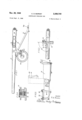
- Figure 1 is a side elevation of a 3.45", 25-pounder recoil-less field. gun constructed in accordance with the invention.
- Figure 2 isv a. plan view of the breech end of the gun with the breech open.
- Figure 3 is a detail plan. view of the breech chamber, to an enlarged scale, showing the ejector mechanism.
- Figure. 4 is a. detail sectional view of one of the breech trunnions.
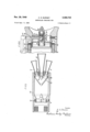
- Figure 6 is an. enlarged detail sectional view of suitable firing mechanism.
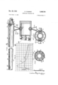
- Figure 7 is a half sectionalv view showing the improved construction of gun barrel according to the invention.
- Figure 8 is'across-section on line VIII-VIII of Figure '7;
- Figure 9- is a. cross-section on line IXIX of.
- FIG. 10 illustrates the pressure A obtained with a prior art gun as. compared with the pressure B obtainedwith the gun of" the present invention, and.
- Figure 11 is a view corresponding to Figure 8 showing another breech chamber construction transport purposes, the end of the trail 13 carrying a suitable coupling eye or hook 14a for towing purposes.
- the gun in this case has a movable breech member 15 disposed between the gas chamber 16 and the gun barrel proper 11, which is rotatable about vertical trunnions 19 midway along its length.
- the portions of the trunnionsshown in detail in Figure 4which are engaged with the breech member 15 consists of diametrical bars 18, and the said bars are formed by two telescopic parts, viz. a plunger and an outer casing, with a spring interposed between the parts, so as to make the bars 18 yielding as to their length, whereby a certain degree of longitudinal move ment of the movable breech member 151s permitted.
- the breech member 15 is opened and closed by a handle 8
- On rotating the handle in a clockwise direction, its first movement rotates a small crank 82, and through a connecting rod 83, applies pressure to a locking pin 84 which bears on the end of the barrel. The consequent reaction shifts the breech member 15 rearwardly,
- a cam 86 on the trunnion axis bears on the tail of the lever 81, and through rod 88 moves the pivoted extractor levers 89 through a small angle of 6, thus loosening the cartridge case in the breech.
- the lever 81 strikes against a fixed stop 90, and the extractor is then moved a further 12 to throw the shell case out of the breech chamber.
- the gas chamber 16 may be constructed internally in the same manner as the modified form of gas chamber 50 illustrated by Fig. 5, in which, instead of employing a swivelled breech member 15, as in Figures 1-4, the gas chamber has an interrupted screw thread engagement with the breech end of the barrel and can swing open angularly in a manner well-known in connection with guns.
- the method adopted for opening and closing the breech forms no part of the present invention.
- the gas chamber 50 corresponds to the gas chamber 16 of Figs. l-4 and it can be assumed that the breech construction illustrated by Fig. 5
- the gas chamber 58 (or 16) has a rear end wall fitted with a ring of fixed expansion nozzles 5
- a cone shaped valve member 56 Supported by spider arms 55 over the inlet end of central nozzle 52 is a cone shaped valve member 56 which is aligned with the end of nozzle 52 and engages therein to agreater or less extent, according as the nozzle 52 is longitudinally adjusted by rotation in a bush in the end wall of chamber 50, with which it has a screw thread engagement.
- the inlet or throat end of nozzle 52 is adjusted in regard to the stationary conical valve member so as to vary its eifective throat area, thereby restricting the rate of escape of the gases and increasing the maximum pressure attained in the gas chamber 50.
- nozzle 52 may thus be adjusted to cause the gun to be recoil-less or to have any desired proportion of its recoil absorbed.
- the edge of the ring 5'? on the nozzle may be indicated by calibrating the edge of the ring 5'? on the nozzle and providing a fixed pointer on the chamber 58 to cooperate with the graduated edge of the ring.
- the firing mechanism may be such as is illustrated by Figure 6.
- Figure 6 shows the cartridge case 58 fitted into the breech member 15, with its base formed by a spider 59 flanged to engage the edge of the chamber, and supporting the percussion cap 60 for the primary charge, axially.
- the percussion cap 68 comes opposite to the centre portion 6! of spider ring 54, when the breech member 15 is in the closed position.
- is hollow and contains the firing pin 62 slidable in a block 63 held in place by conical cover 64.
- the rear end of firing pin 52 is flanged and a spring 64' surrounds the firing pin and bears against the flange so as to withdraw the firing pin.
- a quadrant member 54" which has trunnions journalled in centre portion 6
- One radial edge of the quadrant 6 5" is adapted to bear on the end of the slot in the firing pin, whilst the other radial edge comes beneath a hole in one of the spider arms 54 through which passes the primary striking pin 55.
- the guns of Figures 1-6 are provided with rearwardly directed gas nozzles, so as to be of recoil-less type.
- the invention may be carried out, however, without the aid of the recoil-less principle by directing the gas escape nozzles 5m in directions other than rearwardly, for example, laterally as in Figure 11, the throats of the nozzles 5la being covered with conical grids 53a corresponding to the grid 53 of Figure 5
- the preferred construction of gun barrel for constant pressure guns according to the invention is illustrated particularly by Figures '7, 8 and 9.
- the gun barrel proper 71 consists of a relatively thin walled tube 58 of uniform thickness arcane 7 adequate to Withstand he ma imum pressure of the chamb r Th s. su r unded near ts bre ch e d by a ann ar fitting ompr sin n n er sl v t nc c ng the barrel and spaced therefrom an outer sleeve t'll torming flanges on both sides of an apertured web l'll connecting together the two sleeves 68 and lid.
- the annular fitting extend forwardly along the barrel a plurality of ribs or Webs I12 which radiate from the axis of the barrel and are spaced symmetrically around the, barrel.
- I12 gradually decrease in depth from breech to muzzle, and they may also if desired decrease in thickness.
- the decrease in depth may be uniform, so as to produce a straight line edge,fo r the decrease in depth may vary in accordance with a parabolic law.
- the outer edges of the ribs or webs W2 are preferably flanged on both sides, as shown, and their inner edges are welded to the barrel tube 68 at intervals or continuously along their length.
- the ribs or webs B2 are enclosed by an outer tapering tube H3 preferably attached, as by screws, welding or the like, to the flanged edges of the ribs or webs.
- the breech end of tube H3 is fitted on and secured tothe outer sleeve IE'El of the annular breech fitting, and at its muzzle end the tube is attached to a ring I'M encircling the muzzle end of tube 68.
- the annular fitting 89, H9, H! also carries the trunnions M5 for supporting the gun barrel assembly, and in addition to the forwardly extending ribs H2, is provided with short rearwardly extending tapered webs or ribs 9'58 extending to the screw thread ill by which the barrel assen e bly is screwed into the breech structure of the.
- These webs or ribs Hi6 may be enclosed in a conical sleeve or cover tube fitted on to the rearward flange formed by sleeve 179.
- the ribs or .webs I12 will greatly increase the moment of inertia, and thus the resistance to bending of the barrel as a whole, without unduly increasing its weight in comparison with the increase of weight which would result from increasing the thickness of the barrel tube 65 in order to obtain an equal resistance to bending, which would negative the saving in barrel weight due to the reduction in the maximum chamber pressure obtained as a result of the invention.
- the muzzle portion of the barrel tube 68 may be perforated as shown at I89 in Figure 7, for a suitable length, so as to allow lateral escape of the gases into the interior of the outer casing 6'53, in which case the annular muzzle ring I14 would be perforated, as shown at 81 in Figure 8, to allow the gases to escape into the atmosphere.
- the barrel perforations may be of a total area equal to four times the area of the barrel bore, and the area of the annular space between barrel B8 and outer casing its may be twice said barrel bore area.
- a gun comprising a barrel having a pro- Jec il cc i ing pc ticn at s a nd, a reech cb mbcr i cluding a ar idge p ce ec d tc the nd of the ba r to receive an c lcsiv propc lc charge wh the su s l d.
- the wallet the breech chamber supporting a gas discharge member hav g a e ri t d c t and an outlet opening tothe atmosphere, partof said breech chamber forward of rear wall thereof and additional to the cartridge space forming a gas space of substantial volume in direct communication with both the cartridge space and the throat of said gas discharge member, said cartridge space having a venting area intothe gas space at. least equal to the crosse sectional area of the barrel, and said gas space beingso constructed and arranged that the gases developed by combustion of the propellent charge are free to expand therein when the charge isv ignited, the cross-sectional area of the throat cfisaid as disch e em be n l ss ha that of said barrel,
- a gun according to claim 2 wherein the gun barrel has an outer wall spaced from an inner wall to 10;!!! a chamber between said inner and outer walls, the inner wall being provided with apertures ad acen he u mu zl pla n the bor ntoommuni ation w th th an u space between the inner and outer walls, and means to p ace said annular p c n o ommun catio with the atmosp e- '7.
- a gun according to claim 1 wherein the throat area of the gas discharge. member is substantia1ly-6 cf, the barrel or area- 8-
- su ccor in t la m wh r i an ad ius a e means is p vid d t duc the size of the throat of the gas discharge member.
- a gun according to claim 1 wherein the breech chamber gas space is provided with a perforated element positioned between the cartridge space and the gas discharge member.
Landscapes
- Engineering & Computer Science (AREA)
- General Engineering & Computer Science (AREA)
- Chemical & Material Sciences (AREA)
- Combustion & Propulsion (AREA)
- Toys (AREA)
Description
Nov. 29, 1949 c. D. BURNEY CONTROLLED PRESSURE GUN Filed Sept.
5 Sheets-Sheet 1 .1),Bu/QN2Y Nov; 29, 1949 c- D- BURNEY CONTROLLED PRESSURE GUN 3 She'ets-Sheet 2 Filed Sept. 6, 1945 Inventor D, Bum By y Ma A llorneya Nov. 29, 1949 c. D. BURNEY 2,489,748
CONTROLLED PRESSURE GUN Filed Sept. 6, 1945 3 Sheets-Sheet 3 LEN TH OF BARREL I nvenlor CharlesD.BU/rny Attornev Patented Nov. 29, 1949 OFFICE CONTROLLED PRESSURE GUN Charles Dennistoun Burney, Baynards Park, near Cranleigh, England Application September 6, 1945, Serial No. 614,714 In Great Britain May 7, 1942 7 Section 1, Public Law 690, August 8, 1946 Patent expires May 7, 1962 11 Claims.
The present invention relates to ordnance and has for its general object to improve the performance of guns or like projectors for projectiles, shells or bullets, such as mortars or rifles, in relation to their weight.
As normally constructed the combustion of the propellant in the chamber of a gun gives rise to a sudden and very great rise in pressure immediately after the moment of ignition, followed by a more or less rapid fall of pressure as the projectile moves along the barrel, the pressure being at a minimum when the projectile reaches the muzzle. Consequently beyond a certain point any addition to the length of the muzzle will not add sufficiently to the range to justify the extra weight and loss of mobility of the gun resulting from the increase of length.
Furthermore, as guns are normally constructed the breech chamber and barrel have to be of very heavy construction in order to withstand the great stresses due to the very high maximum pressure in the gun chamber on explosion. Consequently the gun as a whole becomes very heavy.
One object of the present invention is to avoid a very great and sudden rise of pressure on explosion of the propellent charge, thereby elimimating the necessity for heavy breech and barrel construction, with consequent increased mobility of the gun and reduction in fuel consumption costs of gun transport equipment;
Another object is to produce a substantially higher mean pressure, approaching a substantially constant pressure, in the chamber and barrel, whereby any loss of performance due to the reduced maximum pressure may be compensated and even better performance than is possible with guns of normal construction may be obtained by increasing the length of the gun barrel.
The above objects are both achieved, according to the invention, by providing a gun using a cordite or like propellant whose burning rate is dependent upon pressure, the said gun comprisinga barrel having a projectile-receiving portion at its rear end, a breech chamber including a cartridge space fixed to the rear end of the barrel in which an explosive propellent charge is received when the gun is loaded, the wall of the breech chamber supporting a gas discharge member having a restricted throat and an outlet open to the atmosphere, part of said breech chamber forward of the rear wall thereof and additional to the cartridge space forming a gas space of sub-' stantial volume in direct communication with both the cartridge space and the throat of said. gas discharge member, said cartridge space hay-1 ing a venting area into the gas space at least equal to the cross-sectional area of the barrel, and said gas space being so constructed and arranged that the gases developed by combustion of the propellent charge are free to expand therein when the charge is ignited, the cross-sectional area of the throat of said gas discharge member being less than that of said barrel. Preferably the throat area or total throat area of the gas discharge member is less than the barrel bore area. but exceeds 50% of such area, so that escape of the gases through the discharge member will produce a substantially constant pressure in the chamber of the gun (comprising the cartridge and gas spaces) modified by the fall of pressure due to their gradual increase of chamber volume due to the movement of the projectile along the barrel.
It should be understood that in place of a single gas discharge member there may be several of such members and that it is immaterial to the invention in what direction the gases discharge from the gas outlet member or members, although in accordance with my concurrent application for Letters Patent filed September 1, 1944, Serial No. 552,347, they may be discharged rearwardly to reduce or eliminate recoil.
The gas escape member may have a throat area or total throat area which is substantially 66% of the barrel bore area, and preferably the gas discharge expansion nozzle has a throat area or total throat area which is substantially 66% of the barrel bore area.
It will be understood that the resistance of the projectile to movement along the barrel will have the effect of causing the bulk of the gases to discharge through the gas discharge nozzles, notwithstanding that their area is less than the barrel bore area.
The pressure within the breech chamber will be determined jointly by the rate at which the gases can escape through the barrel and gas discharge nozzles respectively, and the adiabatic expansion of the gases through the nozzles will produce a constant pressure in the chamber modified by the fall of pressure due to the gradual increase of the chamber volume due to the movement of the projectile along the barrel. Owing to the large volumes of gases which escape through the nozzles in comparison with the increase of chamber volume due to the travel of the projectile along the barrel, the passage of the projectile along the barrel will have a relatively very small effect on the chamber pressure in comparison .with the eilect due to the nozzles.
Thus, referring to Figure 10, the pressure B pressure curve A of a normal gun, that a substantially higher and more uniform mean pressure is maintained until the projectile leaves the gun muzzle. Since the work done onthe projectile, which produces its velocity, is represented.
by the area beneath the pressure space curve, it follows that with a given length of gun the same velocity can be obtained as with a normal gun with a substantially lower maximum pressure. Furthermore, owing to the shape of the pressure space curve, any increase in the length of the barrel will result in a greater increase of work added, and therefore of velocity produced, than in the case'of a normaljgurrin which the pressure falls off very rapidly towards the muzzle of the gun. Hence increase of the barrel length will be more advantageous in regard to the range or impact velocity obtainable than with a gun of normal construction, subject, of course, to the limiting conditions imposed: by mechanical considerations.
As hereinbefore indicated the gases may be discharged through the expansion nozzle or nozzles in any desired direction, for example in relation tothe axis of the barrel; However, if the expansion nozzle or nozzles is or are directed oppositely from the barrel, the gases discharging rearwardly therefrom at high velocity will produce a reaction in the forward direction, which will balance or partially balance the recoilof the gun to an extent dependent upon the bulk of gases allowed. to escape. through the rearwardly directed nozzle or nozzles. An adjustable valve device may be associated' with. the nozzle or nozzles whereby the throat area may be varied so that any desired proportion of the recoil may be. absorbed up to a maximum of 100%, when the gun will be recoilless. If provision is made for restricting the nozzle area to an even greater extent the barrel inay be given a forward motion instead of a backwardrecoil, which may in certain circumstances be advantageous for the operation of associated mechanism. However, it should be understood that the present invention is not concerned with modifying or eliminating the recoil of guns in the abovemanner, which forms the subject matter of my aforesaid concurrent application for Letters Patent Serial No. 552,347.
On the other hand'it should be appreciated that since reduction of barrel weight is an object of this invention which is realised in part by the reduction of maximum pressure to a value little exceeding the mean. pressure, the maximum advantage in this respect, viz. weight reduction, is obtained if the gun is also made recoil-less, since a direct result of this will be a further reduction in weight due to the. elimination of the normal recoil mechanism. 7 I Although in accordance with the foregoing the invention enablesthe thickness of the chamber wall and thus the weight of. the gun to be reduced,
the possibility of increasing the barrel length to maintain or increasethe range or impact velocity without undue increasevof weight is seriously limited by the whippiness and liability of thin barrels to bend under their own weight and thus produce inaccuracy of fire.
Consequently, in order to enable the advantages of the main feature of the invention to be attained to the fullest extent, a further part of the invention consists in providing the gun with a thin barrel so constructed that its stiffness at right angles to its axis may be increased at all points along its length, without undue increase of weight.
It is a further object of the invention, therefore, to. combine the improved breech with a thin barrel whose length can be increased without reducing its accuracy and yet without increasing its thickness.
According to this part of the invention, the gun comprises a breech portion as hereinbefore indicated in combination with a thin tubular barrel whose rigidity'along its length is increased by a plurality of longitudinal ribs or webs, which decrease. in depth progressively along the barrel, and are preferably spaced uniformly round the periphery of the barrel. In consequence, the Moment of Inertia and thusthe resistance to bending is increased-at all points along the length of the barrel.
The edges of-the ribs or'webs may be straight and uniformly tapered from breech end'to-muzzle end. Also the edges oithe ribs or webs may be flanged preferably on both sides of the webs, so that they are T-shaped-in cross-section. The ribs or webs themselves may be straight, that is, run parallel to the axis of the barrel, or they may be helically arranged.
Preferably the barrel, with its longitudinal webs or ribs, is enclosed by an outer tube, which is preferably attachedasbyscrews, welding, or the like, to the edges or flanges of the ribs orwebs.
In order that the invention may be more clearly understood. and. readily carried into practice it is. illustrated by way of example only, in the accompanying drawings, in which:
Figure 1 is a side elevation of a 3.45", 25-pounder recoil-less field. gun constructed in accordance with the invention.
. Figure 2 isv a. plan view of the breech end of the gun with the breech open.
Figure 3. is a detail plan. view of the breech chamber, to an enlarged scale, showing the ejector mechanism.
Figure. 4 is a. detail sectional view of one of the breech trunnions.
- Figurefiis a sectional view of the breech chamber adapted for. use with a different form of breech mechanism..
Figure 6 is an. enlarged detail sectional view of suitable firing mechanism.
Figure 7 is a half sectionalv view showing the improved construction of gun barrel according to the invention.
Figure 8 is'across-section on line VIII-VIII of Figure '7;
Figure 9-is a. cross-section on line IXIX of.
Figure 7.
; Figure. 10. illustrates the pressure A obtained with a prior art gun as. compared with the pressure B obtainedwith the gun of" the present invention, and.
Figure 11 is a view corresponding to Figure 8 showing another breech chamber construction transport purposes, the end of the trail 13 carrying a suitable coupling eye or hook 14a for towing purposes.
The gun in this case has a movable breech member 15 disposed between the gas chamber 16 and the gun barrel proper 11, which is rotatable about vertical trunnions 19 midway along its length. The portions of the trunnionsshown in detail in Figure 4which are engaged with the breech member 15 consists of diametrical bars 18, and the said bars are formed by two telescopic parts, viz. a plunger and an outer casing, with a spring interposed between the parts, so as to make the bars 18 yielding as to their length, whereby a certain degree of longitudinal move ment of the movable breech member 151s permitted.
The breech member 15 is opened and closed bya handle 8| rotatable in brackets on the side of the breech member, and when the breech is closed the handle 8| occupies the position shown in dotted lines in Figure 2-i. e. pointing towards the rear end of the gun. On rotating the handle in a clockwise direction, its first movement rotates a small crank 82, and through a connecting rod 83, applies pressure to a locking pin 84 which bears on the end of the barrel. The consequent reaction shifts the breech member 15 rearwardly,
which is permitted by the spring trunnion bars 18, thus causing positive disengagement of the breech member 15 from the gun bore. Further movement of the handle 8| carries the crank 82' past its dead centre position and withdraws the locking pin 84 from its hole in the end of the barrel, thus freeing the breech member 15 for rotary movement.
Continued movement of the handle 8| brings it up against a fixed abutment 85 (Figure 2) on the side of the breech member 15, whereupon this member rotates about its trunnions 19 into the position shown in full lines in Figure 2 and dotted lines in Figure 3.
During the initial rotation of the breech member 15 a cam 86 on the trunnion axis bears on the tail of the lever 81, and through rod 88 moves the pivoted extractor levers 89 through a small angle of 6, thus loosening the cartridge case in the breech. As the breech member 15 swings into the fully open position the lever 81 strikes against a fixed stop 90, and the extractor is then moved a further 12 to throw the shell case out of the breech chamber.
The gas chamber 16 may be constructed internally in the same manner as the modified form of gas chamber 50 illustrated by Fig. 5, in which, instead of employing a swivelled breech member 15, as in Figures 1-4, the gas chamber has an interrupted screw thread engagement with the breech end of the barrel and can swing open angularly in a manner well-known in connection with guns. The method adopted for opening and closing the breech, however, forms no part of the present invention.
The gas chamber 50 corresponds to the gas chamber 16 of Figs. l-4 and it can be assumed that the breech construction illustrated by Fig. 5
is applicable to the gun of Figs. 1-4, apart from the forward end of the gas chamber shownin Fig. 5, carrying the interrupted screw thread.
The gas chamber 58 (or 16) has a rear end wall fitted with a ring of fixed expansion nozzles 5| and a central adjustable nozzle 52, through which the gases escape rearwardly in relation to the direction of aim of the gun. Over the nozzle openings in the end wall is mounted a cess to the nozzle openings.
" tail in Fig. 6 as applied to the form of breech block shown in Figs. 1-4.
Supported by spider arms 55 over the inlet end of central nozzle 52 is a cone shaped valve member 56 which is aligned with the end of nozzle 52 and engages therein to agreater or less extent, according as the nozzle 52 is longitudinally adjusted by rotation in a bush in the end wall of chamber 50, with which it has a screw thread engagement. Thus the inlet or throat end of nozzle 52 is adjusted in regard to the stationary conical valve member so as to vary its eifective throat area, thereby restricting the rate of escape of the gases and increasing the maximum pressure attained in the gas chamber 50. The
' nozzle 52 may thus be adjusted to cause the gun to be recoil-less or to have any desired proportion of its recoil absorbed. The setting of the nozzle,
may be indicated by calibrating the edge of the ring 5'? on the nozzle and providing a fixed pointer on the chamber 58 to cooperate with the graduated edge of the ring.
The firing mechanism may be such as is illustrated by Figure 6. This figure shows the cartridge case 58 fitted into the breech member 15, with its base formed by a spider 59 flanged to engage the edge of the chamber, and supporting the percussion cap 60 for the primary charge, axially. The percussion cap 68 comes opposite to the centre portion 6! of spider ring 54, when the breech member 15 is in the closed position. The said centre portion 6| is hollow and contains the firing pin 62 slidable in a block 63 held in place by conical cover 64. The rear end of firing pin 52 is flanged and a spring 64' surrounds the firing pin and bears against the flange so as to withdraw the firing pin. Further forward the firing pin is slotted and in the slot is engaged a quadrant member 54" which has trunnions journalled in centre portion 6|. One radial edge of the quadrant 6 5" is adapted to bear on the end of the slot in the firing pin, whilst the other radial edge comes beneath a hole in one of the spider arms 54 through which passes the primary striking pin 55. By striking the outer end of pin 56, as by means of a pivoted hammer 61, an impulse is transmitted to quadrant G4 which is transferred to the firing pin 52 and drives it forwardly against the percussion cap 60, after which it is withdrawn again by the spring 64'.
It will be understood that the guns of Figures 1-6 are provided with rearwardly directed gas nozzles, so as to be of recoil-less type. The invention may be carried out, however, without the aid of the recoil-less principle by directing the gas escape nozzles 5m in directions other than rearwardly, for example, laterally as in Figure 11, the throats of the nozzles 5la being covered with conical grids 53a corresponding to the grid 53 of Figure 5 The preferred construction of gun barrel for constant pressure guns according to the invention is illustrated particularly by Figures '7, 8 and 9.
The gun barrel proper 71 consists of a relatively thin walled tube 58 of uniform thickness arcane 7 adequate to Withstand he ma imum pressure of the chamb r Th s. su r unded near ts bre ch e d by a ann ar fitting ompr sin n n er sl v t nc c ng the barrel and spaced therefrom an outer sleeve t'll torming flanges on both sides of an apertured web l'll connecting together the two sleeves 68 and lid. Frcm the annular fitting extend forwardly along the barrel a plurality of ribs or Webs I12 which radiate from the axis of the barrel and are spaced symmetrically around the, barrel. I12 gradually decrease in depth from breech to muzzle, and they may also if desired decrease in thickness. The decrease in depth may be uniform, so as to produce a straight line edge,fo r the decrease in depth may vary in accordance with a parabolic law. The outer edges of the ribs or webs W2 are preferably flanged on both sides, as shown, and their inner edges are welded to the barrel tube 68 at intervals or continuously along their length.
The ribs or webs B2 are enclosed by an outer tapering tube H3 preferably attached, as by screws, welding or the like, to the flanged edges of the ribs or webs. The breech end of tube H3 is fitted on and secured tothe outer sleeve IE'El of the annular breech fitting, and at its muzzle end the tube is attached to a ring I'M encircling the muzzle end of tube 68.
The annular fitting 89, H9, H! also carries the trunnions M5 for supporting the gun barrel assembly, and in addition to the forwardly extending ribs H2, is provided with short rearwardly extending tapered webs or ribs 9'58 extending to the screw thread ill by which the barrel assen e bly is screwed into the breech structure of the.
gun. These webs or ribs Hi6 may be enclosed in a conical sleeve or cover tube fitted on to the rearward flange formed by sleeve 179.
It will be appreciated that the ribs or .webs I12 will greatly increase the moment of inertia, and thus the resistance to bending of the barrel as a whole, without unduly increasing its weight in comparison with the increase of weight which would result from increasing the thickness of the barrel tube 65 in order to obtain an equal resistance to bending, which would negative the saving in barrel weight due to the reduction in the maximum chamber pressure obtained as a result of the invention.
For reasons of stability of the projectile, particularly when self propelled or rocket projectiles are used, it may be desirable to destroy the pressure of the gases on the base of the projectile before it leaves the muzzle. To achieve this end the muzzle portion of the barrel tube 68 may be perforated as shown at I89 in Figure 7, for a suitable length, so as to allow lateral escape of the gases into the interior of the outer casing 6'53, in which case the annular muzzle ring I14 would be perforated, as shown at 81 in Figure 8, to allow the gases to escape into the atmosphere. With such a construction the barrel perforations may be of a total area equal to four times the area of the barrel bore, and the area of the annular space between barrel B8 and outer casing its may be twice said barrel bore area. The sudden increase of the barrel volume when the projectile passes the perforations will cause a sudden drop in the chamber pressure, to such an extent that the combustion of the propellant is reduced in speed or even brought to an end be? fore the charge is fully burnt, so that the pressure acting on the base of the projectile on leav- These eb 8 ms th much reduced a is entirely imi ated This invention is distinguished from that of my p r but cc c rrc ap icat on for Letters atent s ria 552 in. t at the gas sharged r m the br ech ch m ma b scharged in any desired direction in the case of t e present inven ion whereas n h se c my, said p i r pplicatio t e ga u be is char ed i t arward dire tion s as part ally or whcl y tc eliminate recoi he sun- Thus the p ior appli ation e ate to a pa t c s cf he Pr e t in ent on cr a wa d harge of the gases when t e ad i na advan age mcnt cn d above, is obt ined 1 c aim;
1. A gun comprising a barrel having a pro- Jec il cc i ing pc ticn at s a nd, a reech cb mbcr i cluding a ar idge p ce ec d tc the nd of the ba r to receive an c lcsiv propc lc charge wh the su s l d. the wallet the breech chamber supporting a gas discharge member hav g a e ri t d c t and an outlet opening tothe atmosphere, partof said breech chamber forward of rear wall thereof and additional to the cartridge space forming a gas space of substantial volume in direct communication with both the cartridge space and the throat of said gas discharge member, said cartridge space having a venting area intothe gas space at. least equal to the crosse sectional area of the barrel, and said gas space beingso constructed and arranged that the gases developed by combustion of the propellent charge are free to expand therein when the charge isv ignited, the cross-sectional area of the throat cfisaid as disch e em be n l ss ha that of said barrel,
.2- A sum accord to cla m 1, whe n h barrel of the gun is made of relatively thin metal and is stifilened against bending by longitudinal external ribs decreasing in depth from the barrel breech towa ds t e bar e m zz e.-
.3. gun, according to claim 2 wherein the ou er edg s of the ri s are l de. ,A sun a o di g to a m 2 wh t longitudinal ribs extend parallel to the muzzle axis- 5. A gun according to claim 2 wherein the gun barrel is enclosed in an outer tube positioned concentrically with the barrel and spaced from the barrel by said ribs.
6. A gun according to claim 2 wherein the gun barrel has an outer wall spaced from an inner wall to 10;!!! a chamber between said inner and outer walls, the inner wall being provided with apertures ad acen he u mu zl pla n the bor ntoommuni ation w th th an u space between the inner and outer walls, and means to p ace said annular p c n o ommun catio with the atmosp e- '7. A gun according to claim 1, wherein the throat area of the gas discharge. member is substantia1ly-6 cf, the barrel or area- 8- A gun accord ng c aim 1, wherein s d ha ge memb r is a ccni al p nsion. noz 1e.-
9- A su ccor in t la m wh r i an ad ius a e means is p vid d t duc the size of the throat of the gas discharge member.
1 gun acco din t cla m 1 cludi g a rin me e ass at d wi he throat of the as di char e memb a d a on ca exp n nncz e adiu ta y m va le wi respect to he opening in said rin memb r, whereby the effec tive area of the ring member opening may be reduced.
11. A gun according to claim 1, wherein the breech chamber gas space is provided with a perforated element positioned between the cartridge space and the gas discharge member.
CHARLES DENNISTOUN BURNEY.
REFERENCES CITED The following references are of record in the 10 file of this patent:
UNITED STATES PATENTS Number 10 FOREIGN PATENTS Country Date Great Britain A. D. 1910 Great Britain Apr. 17, 1919 Great Britain May 15, 1919 Australia Sept. 25, 1919 France Dec, 11, 1925 Great Britain July 8, 1937 Sweden Aug. 10, 1937 Switzerland Mar. 17, 1941 OTHER REFERENCES
Applications Claiming Priority (1)
| Application Number | Priority Date | Filing Date | Title |
|---|---|---|---|
| GB2489748X | 1942-05-07 |
Publications (1)
| Publication Number | Publication Date |
|---|---|
| US2489748A true US2489748A (en) | 1949-11-29 |
Family
ID=10908230
Family Applications (1)
| Application Number | Title | Priority Date | Filing Date |
|---|---|---|---|
| US614714A Expired - Lifetime US2489748A (en) | 1942-05-07 | 1945-09-06 | Controlled pressure gun |
Country Status (1)
| Country | Link |
|---|---|
| US (1) | US2489748A (en) |
Cited By (8)
| Publication number | Priority date | Publication date | Assignee | Title |
|---|---|---|---|---|
| US3028125A (en) * | 1952-07-11 | 1962-04-03 | Atlantic Res Corp | Catapult |
| US3035494A (en) * | 1960-01-26 | 1962-05-22 | Musser C Walton | Recoil adjusting device |
| US3088225A (en) * | 1960-05-26 | 1963-05-07 | Amistadi E Henry | Subcaliber howitzer trainer |
| US3194118A (en) * | 1963-01-28 | 1965-07-13 | Musser C Walton | Recoilless gun for simultaneously separately loading propellant and projectile |
| US4141275A (en) * | 1977-07-14 | 1979-02-27 | The United States Of America As Represented By The Secretary Of The Navy | Afterburner recoilless rifle |
| US4284164A (en) * | 1979-12-21 | 1981-08-18 | Atlantic Richfield Company | Acoustic pulse generator |
| US10788284B1 (en) * | 2019-05-09 | 2020-09-29 | The United States Of America As Represented By The Secretary Of The Army | Grounded and vehicular mounted weapons with improved recoil stability |
| US20220146218A1 (en) * | 2019-03-04 | 2022-05-12 | Samuel DESSET | Active device for total inhibition of the recoil of firearms in the axis of the barrel |
Citations (8)
| Publication number | Priority date | Publication date | Assignee | Title |
|---|---|---|---|---|
| GB125126A (en) * | 1900-01-01 | |||
| GB191012227A (en) * | 1910-05-18 | 1910-12-01 | James Eastwick | Improvements in Barrels for Small Arms and Machine Guns. |
| GB126336A (en) * | 1916-12-20 | 1919-05-15 | Andrew Jackson Stone | Improvements connected with Ordnance. |
| US1380358A (en) * | 1920-03-24 | 1921-06-07 | Charles J Cooke | Non-recoil gun |
| FR601830A (en) * | 1925-07-06 | 1926-03-08 | Handheld weapon throwing grenade shells | |
| GB468583A (en) * | 1936-04-07 | 1937-07-08 | Robert Henry Smith Hughes | Improvements in devices for reducing the recoil of firearms |
| CH212873A (en) * | 1937-05-08 | 1940-12-31 | Financieres & Ind S A E F I S | Self-propelled projectile and its launch tube. |
| US2405414A (en) * | 1944-04-05 | 1946-08-06 | Carolus L Eksergian | Recoilless gun mechanism |
-
1945
- 1945-09-06 US US614714A patent/US2489748A/en not_active Expired - Lifetime
Patent Citations (8)
| Publication number | Priority date | Publication date | Assignee | Title |
|---|---|---|---|---|
| GB125126A (en) * | 1900-01-01 | |||
| GB191012227A (en) * | 1910-05-18 | 1910-12-01 | James Eastwick | Improvements in Barrels for Small Arms and Machine Guns. |
| GB126336A (en) * | 1916-12-20 | 1919-05-15 | Andrew Jackson Stone | Improvements connected with Ordnance. |
| US1380358A (en) * | 1920-03-24 | 1921-06-07 | Charles J Cooke | Non-recoil gun |
| FR601830A (en) * | 1925-07-06 | 1926-03-08 | Handheld weapon throwing grenade shells | |
| GB468583A (en) * | 1936-04-07 | 1937-07-08 | Robert Henry Smith Hughes | Improvements in devices for reducing the recoil of firearms |
| CH212873A (en) * | 1937-05-08 | 1940-12-31 | Financieres & Ind S A E F I S | Self-propelled projectile and its launch tube. |
| US2405414A (en) * | 1944-04-05 | 1946-08-06 | Carolus L Eksergian | Recoilless gun mechanism |
Cited By (9)
| Publication number | Priority date | Publication date | Assignee | Title |
|---|---|---|---|---|
| US3028125A (en) * | 1952-07-11 | 1962-04-03 | Atlantic Res Corp | Catapult |
| US3035494A (en) * | 1960-01-26 | 1962-05-22 | Musser C Walton | Recoil adjusting device |
| US3088225A (en) * | 1960-05-26 | 1963-05-07 | Amistadi E Henry | Subcaliber howitzer trainer |
| US3194118A (en) * | 1963-01-28 | 1965-07-13 | Musser C Walton | Recoilless gun for simultaneously separately loading propellant and projectile |
| US4141275A (en) * | 1977-07-14 | 1979-02-27 | The United States Of America As Represented By The Secretary Of The Navy | Afterburner recoilless rifle |
| US4284164A (en) * | 1979-12-21 | 1981-08-18 | Atlantic Richfield Company | Acoustic pulse generator |
| US20220146218A1 (en) * | 2019-03-04 | 2022-05-12 | Samuel DESSET | Active device for total inhibition of the recoil of firearms in the axis of the barrel |
| US11624567B2 (en) * | 2019-03-04 | 2023-04-11 | Samuel DESSET | Active device for total inhibition of the recoil of firearms in the axis of the barrel |
| US10788284B1 (en) * | 2019-05-09 | 2020-09-29 | The United States Of America As Represented By The Secretary Of The Army | Grounded and vehicular mounted weapons with improved recoil stability |
Similar Documents
| Publication | Publication Date | Title |
|---|---|---|
| US2466714A (en) | Recoilless firearm and ammunition therefor | |
| US3490330A (en) | Firearm,particularly light antitank weapon | |
| US2790353A (en) | Feeding mechanism for a firearm | |
| US4676136A (en) | Apparatus for recoilless firing of projectiles from a lauching tube | |
| US2489748A (en) | Controlled pressure gun | |
| US2409225A (en) | Gas system for firearms | |
| US3557550A (en) | Pressure-controlled bomb ejector for aircraft | |
| US2472111A (en) | Recoilless firearm and ammunition therefor | |
| US2598256A (en) | Recoilless gun | |
| RU2696949C9 (en) | Universal artillery complex for telescopic cartridge | |
| DK142964B (en) | PROJECTIL WITH FIRE BEETS | |
| US2249310A (en) | Gun mounting for machine guns adapted to recoil | |
| US4934242A (en) | Liquid propellant gun for projectiles of different masses and velocities | |
| RU2669037C2 (en) | Automatic weapon with inner piston for caseless cartridge | |
| US6964220B1 (en) | Floating barrel handgun method of recoil elimination | |
| US2470489A (en) | Rifle rocket missile | |
| US2489747A (en) | Reduced recoil type gun | |
| US3496828A (en) | Percussion device for firearms | |
| US4084480A (en) | Lightweight small craft gun system | |
| US2537063A (en) | Breech and firing mechanism for recoilless firearms | |
| US3270618A (en) | Controlled recoil weapon | |
| US3653288A (en) | Tubular-shaped launcher for projectiles, in particular for missiles | |
| CN109990655A (en) | Preposition nozzle formula pneumatic type for more bullets series connection transmitting cannon subtracts recoil device | |
| US3013472A (en) | High velocity multi-stage guns | |
| US3174401A (en) | Actuating mechanism for automatic shotgun |