US2334154A - Feed regulator for sewing machines - Google Patents
Feed regulator for sewing machines Download PDFInfo
- Publication number
- US2334154A US2334154A US422790A US42279041A US2334154A US 2334154 A US2334154 A US 2334154A US 422790 A US422790 A US 422790A US 42279041 A US42279041 A US 42279041A US 2334154 A US2334154 A US 2334154A
- Authority
- US
- United States
- Prior art keywords
- arm
- slide
- block
- adjusting rod
- feed
- Prior art date
- Legal status (The legal status is an assumption and is not a legal conclusion. Google has not performed a legal analysis and makes no representation as to the accuracy of the status listed.)
- Expired - Lifetime
Links
Images


Classifications
-
- D—TEXTILES; PAPER
- D05—SEWING; EMBROIDERING; TUFTING
- D05B—SEWING
- D05B3/00—Sewing apparatus or machines with mechanism for lateral movement of the needle or the work or both for making ornamental pattern seams, for sewing buttonholes, for reinforcing openings, or for fastening articles, e.g. buttons, by sewing
- D05B3/06—Sewing apparatus or machines with mechanism for lateral movement of the needle or the work or both for making ornamental pattern seams, for sewing buttonholes, for reinforcing openings, or for fastening articles, e.g. buttons, by sewing for sewing buttonholes
- D05B3/08—Sewing apparatus or machines with mechanism for lateral movement of the needle or the work or both for making ornamental pattern seams, for sewing buttonholes, for reinforcing openings, or for fastening articles, e.g. buttons, by sewing for sewing buttonholes for buttonholes with eyelet ends
Definitions
- buttonhole se ing machine In'the use of buttonhole se ing machine s'rit is frequently necessary when changing from one character of-work to another that thenumber of stitches required in the entire buttonholeihe venient application upon machines already in the V varied. It is, of coursegdesirablga that the hut- 10 tonhole machine be equipped with a suitable feed-regulator which J will provide means conveniently accessible for manipulationtby' the operator by which the number of stitches produced the solution of this problem that applicant has addressed himself. r f
- a further object of thepresent invention is the provision of aieed-regulator designed sothat 5 adjustment of the number of stitches comprising the .buttonholemay. be made'overa wide range.
- a still further object of the p ifes'ent invention isthe provisionof a feed-regulator for buttonhole machines whichis' capable' of being operated to change the number oistitches in a button hole duringflthe operation of the machine.
- the' invention comprises in the buttonhole may be varied, It is toward 15 provided which the number of stitchesin the '20 buttonhole could be controlled, However, ef
- Another object of thepresent invention is the' j provision of an improved feed regulator device ,which is self -contained and adapted for icon- 55 skilled in jithje art. 9
- Fig. 4 is an nlarged vertical sectional View 7 taken transversely of the slotted arcuat'e clutchactuating arm and through. the. slide-block M mounted thereon, showingfthe linkconection with the slide-block; the parts illustratedbeing. shown in aninverted position.
- K 1 Fig. 5 is an, enlarged horizontal "section-a1 view takenthrough the right angle brackeh'whichis H buttorihole "without having” to displace t -but- ,ceiving spindle.
- Figf'l is a vertical sectional view taken through the bed, 1 illustrating ,a modification of the [feedregulatonplemental to the needle 7 in the formation of lock? g:
- the preferred jm eansemployed for shifting sli iierblock'fi lengthwise for the clutch-actuating "arm 24 comprises a screw-'thr'eadedfrod 3'6 hav ing threaded-thereon intermediate its ends spaced ears "3'?"depending from the slide-block 23.
- the slidblook 23 is preferably attached to the clutcheactuat ing arm 2'4 by means of a-slide 3 8 located in the 'T-s'haped sldb Ofjt'he clutchfact uatingarmwhich slide U8 pivotally secured to the slide-block 23 by the stud 4'8
- the screwthreaded rod isjournaled at its inner end in 'trie menace through mechani'sm designed toimpartuntermittent. rotary movement to the feed-shaft. It is to animprovement in a portion of thishiechani sn'i that the presentinventi'on is directed. a ⁇ l hown in Figs.
- the rod 'sfi is; preferably provided on its inner 'end with Ia bevel gear -48 in 'mes h 'wi-th a'se'cond bev-el gear 'jourrraled in v the "supporting bracket--H.
- fsicrew threaded rod 38 is "prevented from moving end iser'e'lative to its supporting bracket-41 by thegear tft em; a collar 4 3" which is-secure'd on the a seby e set-screwts" (Fig, '5).- The 2 5% the bottom face of an internalspiderpr v I clutch-plate 21 which is formed with three peripheral notches '28 having slightly eccentric b'ot- 1 tom walls 29.
- This me'ansis n '-th outer 'endofthe spindle 4% is formed into 21 te f'perclhekagdnal head '46 disposed to ccnveni en't- I ly'i'eceive the end of a Wrench 4% (shown in "djott ed lines in Fig; 2), 'a'daptedto be inserte'd tlirou'giha suitable'jclearance aperture 48 provided -"i'h-t e side wa-l-lcf the usual machine-supporting I 9 show-nth dot dash lines in' Fig. 1--.
- tubular rock-shaft it is formed with an arm 52 slotted as at 53 to receive aslide-block 54 to whichis connected by a stud 55 the lower end of the pitman My At- 'through a clearance opening 63 formedin th depending side-Walled of the bed l.
- patent to work-clainp including, an intermittent actuated device, an arm connected with said intermittent actuated deviceand having an arcuate longitudinal slot formed therein, a slide-block adjustably disposed lengthwiseof saidelongated slot, said adjusting rod being threaded into said slidereceived in said slot, actuating mechanism'connected to saidfslide-block for imparting oscillations to said arm,and a pivotally mounted screwthreaded adjusting rod disposed lengthwise of 'said slot andthreaded into said slide-block, said adjusting rod having means 'at one endadapted to receive a wrench by which theadjusting rod can be conveniently turned to move the slideblock lengthwise of said arm.
- a frame a worn-clamp, and means forimparting work-advancing movements to said work-clamp including, an intermittent actuated devicemounted to operate about a fixed axis, an arm connected to "said intermittent actuated device and formed with an arcuate elongatedslot, a slide-block adjustably' mounted in said slot, actuating mechanism connected to said slideblock for imparting oscillations to'saidarm, a
- an arm connectedto said feed+shait and formed withan arcuate elongated slot, a slide-block adjustably mounted in said slot, actuating mechanism connected to said slide-block for imparting oscillations to said arm, a supporting bracket freelyjournaled upon said feed-shaft adjacent said arm, a screw-threaded adjusting rod secured againstendwise movement in said bracket and block, and means provided at one end of said adjusting rod adapted to receive a wrench by which the adjusting rod, can be conveniently turned to shift the slide-block lengthwise of said 1 slot.
- a group-stitch sewing machine having a frame, a work-clamp, and meansior imparting work-advancing movements to said work-clamp including, an intermittent actuated device, an actuating arm connected, with said device, a slideblock, means securing said slide-block on said actuating arm and permitting adjustment of said slide-block lengthwise of said arm, actuating mechanism connected to said slide-block for imparting movement to said actuating arm, a screwthreaded adjusting rod disposed lengthwise of said arm and threaded into said slide-block, a spindle, having an axis disposed at an angle to the axis of said adjusting rod, means operatively v onnecting said spindle with said adjusting rod, 1 and meansprovided on said;spindle by which it can be, conveniently turned torotate said adjusting rod and shift the slide-block lengthwise of said arm; i i
- a group-stitch sewing machine having a frame, a work clamp, and means for imparting work-advancing movements to saidwork-clamp including, an intermittent actuated device, an actuating arm connected with said device, a-slideblock, means securing said slide-block on said Y actuating arm and permitting adjustment of said slide-block lengthwise of said arm, actuating mechanism connected to said slide-block for imincluding,
- actuating arm connected with said device, a slideblock, means securing said slide-block on said. actuating arm and permitting. adjustment of said slide-block lengthwise of said arm, mechanism connected to said slide-block for imparting movement to said actuating arm, a screw-threaded adjusting rod disposed lengthwise of said arm and threaded intosaidslide-block, a gear mounted on said adjusting rod, a'spindle having an axis disposed at an angle to the axis of said adjusting "rod, a gear mounted on said spindle andlin mesh with the gear on said adjusting rod, and means provided on said spindle by whichit can be. con-- veniently turned to rotate said adjusting rod and shift the slide-block lengthwise of saidarm.
- - actuating arm connected with said device and formed with an arcuate elongated slot,'a slideblock adjustably mounted in' said slot, actuating mechanism connected to said slide-block for imparting oscillations to said'actu'atin'g arm, a pivotally mounted supporting bracket positioned adjacent said actuating arm, a screw-threaded adjusting rod rotatablypmounted in said bracket 'an'd-disposed lengthwise of said elongated slot, said adjustingro-d being threaded into saidslideblock, a gear fixed on said adjustingro'd, a spindle; journaled in said supporting-bracket and arranged atan angle to said adjusting rod, a gear fix-ed on said spindle and in mesh with the gear on said adjusting rod, and means provided on-one end of said spindle to receive a wrenchby which the-adjusting rod can be turned to shift the" slideblock lengthwise of said slot.
- a, group-stitch sewing machine having a frame; a work-clamp, and means for imparting work-advancing movements to said work -clamp an intermittent actuated device mounted to operate about a fixed axisr an actuating arm connected to said intermittent actuated device and mounted for oscillatory movements about said n xed axis of said intermittent, actuated device, saidactuating arm formed with [an arcuate' elongated slot, at s-lide block adjustabiy mounted insaid slot, operating mechanism connected to said slide-block for imparting oscillations to 'said' actuating arm, asupportinge bracket positioned adjacent said actuating arm the fixed axis; t said intermittent-actuated device, a screw-threaded adjusting rod 'rota tably mounted in said bracket and disposed lengthwise t andin mesh with the gear on said adjusting rod,
- a group-stitch sewing machine having, in, combination, a frame, stitch-forming? mechanism including a needle, a work-clamp, and means for imparting relative movements between said work-clamp and needle including, an intermittent.
- actuated device an arm connected with said intermittent actuated device and having anarcuate longitudinal slot formed therein, a slide-block adiustabl rcceivedin saidslot, actuating mechanism connected to said slide-block for imparting oscillations to said arm, and means for shifting saidslide-blook insaid' arcuate slot, said lastnaimed means including a bracket located beneath said intermittent actuated.
- a screw-threaded adjusting rod journaled for rotation in said bracket and threaded into said slide-block, means for securing said screw-threaded adjusting rod against endwise movement relative to said bracket, and means provided-at one end of said screwthreaded adjusting rod adapted to receive, a wrench by which the adjusting rod can be conveniently rotated to, move the slide-block 1ength' wise of said arm.
- a buttonholeisewing machine having a .frame including a bracket arm and a bed-structure provided with a clearance aperture, 2. feedlshaft journaled in said frame and having its lower" end extending within said bed-structure, "an intermittent actuated device operatively connected to the lower end of said feed-shaft, mechanism for operating said intermittent actuated device including an arm; formed with an arcuate slot, 2. slide-block adjustably mounted in said slot,
- stitcmforming mechanism including a needle, a Work-clamp,v and means for imparting relative movements between said workclamp and needle including, anintermittent actuated device, an arm connected with said intermittent actuated device and having an arouate-lengitudinal slot formedtherein, a slide-block adjustably received in said slot, actuating mechanism connectedfto said slide-block for imparting oscillations to said arm, and means 'for shiftmg said slide-block in said arcuate slot, said lastnamed means including a pivotal bracket located beneath said intermittent actuated device andv supported for swlnging'movement'about an" axis,
- a feed-regulator adapted for use in a groupi stitch sewing machine having a, feed-shaft, co nprising, an intermittent actuated devicecfor'imparting operative movements tosaid feed-shaft,
Description
Nov. 9, 1943. A. R. WOOD FEED-REGULATOR FOR SEWING MACHINES 3 Sheets-Sheet 1 Filed Dec. 15, 1941 Mommy fir 0496 602 2. ll/00a? &
NOV. 9, 1943. R WOOD FEED-REGULATOR FOR SEWING MACHINES Filed DecflS, 1941 3 Sheets-Sheet 2 Sla Nov. 9, 1943. A. R. WOOD 2,334,154
FEED-REGULA'I'QR FQR SEWING MACHINE:
Filed Dec. 13, 1941 3 Sheets-Sheet 5 M l/real L Zdooa? tion.
Patented Now 9, 1943 UNITEDJSTATES; PATENT {OFFICE l f. 2,ss4,154t"fi .0 rEEiiREoonATortFo sliwrneivmoirmas Alfred R. Wood; liridgeportjconnl, assigr'ionto TheSing'er Manufacturing" Company, Elizabeth, N. J a, corporation of New Jersey npplication'becernber 1s, 1941;Ma a-422m This invention relates to sewingmachinesand more particularly to an improvement in feedregulators for buttonhole' sewing machines of the type disclosed in the II. S. patent to E. B. Allen, No. 784,291, issued March "1, 1905,
In'the use of buttonhole se ing machine s'rit is frequently necessary when changing from one character of-work to another that thenumber of stitches required in the entire buttonholeihe venient application upon machines already in the V varied. It is, of coursegdesirablga that the hut- 10 tonhole machine be equipped with a suitable feed-regulator which J will provide means conveniently accessible for manipulationtby' the operator by which the number of stitches produced the solution of this problem that applicant has addressed himself. r f
In prior machines of. the type illustrated in the above mentioned Allen paten'tQme'ans were fecting an adjustment of said means it was necessary to. displace the machine out of its normal A further object of thepresent invention is the provision of aieed-regulator designed sothat 5 adjustment of the number of stitches comprising the .buttonholemay. be made'overa wide range. A still further object of the p ifes'ent invention isthe provisionof a feed-regulator for buttonhole machines whichis' capable' of being operated to change the number oistitches in a button hole duringflthe operation of the machine.
Q YWith the aboveand other objects in' View, as
. willhgreinai'trappear, the' invention comprises in the buttonhole may be varied, It is toward 15 provided which the number of stitchesin the '20 buttonhole could be controlled, However, ef
machine. Moreover,-sinceno micrometer adj ust- Vment was provided on the prior machinesa trialand-error method had to be followed'fin'orjdei' to obtain the correct number of stitches in the tonhole. During-the procedure of obtaining the proper number of stitches, the sewing mach'ine;
had to be-repeatedly titled backwardlybetiiveh adjustments, thus requiring the expenditure of considerable effort by the operator in endeavoring, to, obtain the desired number of stitchesinthe buttonhole.
Therefore, it is the primary object of the pres ent invention to provid'e'an improved feed-reguiator for buttonholemaohiries' which will permit the adjustment of the riumber of stitches in the tonhole machine from its normal operating. posi- It is a further objector theinvention to provide an improved f eed-regulatorior buttonhole' machines with which major orminoradjustments can be accomplished with equal iacilit'y.
Another object of thepresent inventionis the' j provision of an improved feed regulator device ,which is self -contained and adapted for icon- 55 skilled in jithje art. 9
the devicesgcombinations and. arrangements of parts hereinafter set forth and illustrated ihfthe accompanying drawingsof apreferred embodiment of the invention. from whioh 'the several. ieaturesoi the invention and the'advantagesattained thereby will be readily understood by those The invention will ferringfltothe accompanying drawings, in which: Fig.-.l isa rightside elevational viewbf a Singer. Ciass- 71 b'uttonhole'sewing machine equipped with a preierre'd 'forni'p'f theinventi'on,
showing the machinetin fulllines and the sup,-
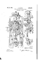
portingbase uponiwhich the machine rests in dot- Fig. 2 is. a bottom lofthe shown in Fig. 1, with the wrench iisedtolaldjust the feed'-.regulator inidotted lines-f 1 Fig; 31s a vertical sectional view taken through the standard. or" the machine, showing the driving connections'between the main-shaft and the 5 feed-shaft actuating. clutch.
Fig. 4 is an nlarged vertical sectional View 7 taken transversely of the slotted arcuat'e clutchactuating arm and through. the. slide-block M mounted thereon, showingfthe linkconection with the slide-block; the parts illustratedbeing. shown in aninverted position. K 1 Fig. 5 is an, enlarged horizontal "section-a1 view takenthrough the right angle brackeh'whichis H buttorihole "without having" to displace t -but- ,ceiving spindle.
freely f ulcrurned upon lower ,end of the feedshaft; showing the bevel-gear connection between the threaded adjustingi rod andfthe wrench-rehdis aveirtical sectional view taken stantially along the line.8-'8; Fig. '1.
in see eva e v ar:
larged vertical sectional view takensubstantially along the line 6'6, Fig; 2.. i
o Figf'l is a vertical sectional view taken through the bed, 1 illustrating ,a modification of the [feedregulatonplemental to the needle 7 in the formation of lock? g:
stitches is a conventionalcscillating shuttle. 3
with thestitch-forming mechanism to properly shift the work-clamp andproduce the desired buttonhole or tack determined bylthe cam grooves cut in the feed-cam I I. 4
The internal clutch-plate 21 and the clutchcylinders 3| areretained in position within the flange 3i! provided on the feed-cam H by means of a, spring-plate 33 which is secured upon the reduc d l'cwer. end-portion; :34 of the feed-shaft driven by the bed-shaft fi operativelyconnected to the main-shaft 5 in a manner represented in U. s, Patent No. "134,291, issued to E. B...A.11..enl1 n March 7, 1 905. I a v a As is. customary in machines of the ty zie se i of the feed-shaft I2, and that by varying this lected to illustrate the present invention, the Work to be sewn is retained in a work-clamp'rep:
resentedby the reference numeral 10. By means of" th'e 'workwlamp the work is slowly moved ten-bws p f on n er end rec p cj'atoryand iaterally'vibratory needle 1; first-away from the standard 2 and then towards thestanfdjo 'cause 'thejfirst and'seco'nd rows of side s v barring 'stitche's may "beformed prothe-machinei's fitted with'a barringdevice. The "workclamp" "l0 derives its '"step-by-step to be laid side by side in the work. v erows' of side stitches the usual movementsfrcm'in feed-cam-H secured upon the}owe;- end of'a feed-shaft I2: the connections between the'work-clamp and feed-cam being con- ;j stl ilc'ted subsjtantiallyid accordance with the d c osli'ie in the U55. Patent-No. 785,061, 'issued Thej feed-shait I2 is operatively 'connected tfo I2 by a nut 35, see Fig. 6.
a It will be understood from the accompanying drawings taken in connection with the above description that the amount. of turn imparted to the"- f eedsha-,ft for each rotation of the mainsl ratt 5 depends upon the distance the slideblock :23 is" removed from the longitudinal axis distance the amount of turn imparted to the teed-Jshaftand consequently the spacing between successive stitchesin the buttonhole or tack may l ef-controlled.
The preferred jm eansemployed for shifting sli iierblock'fi lengthwise for the clutch-actuating "arm 24 comprises a screw-'thr'eadedfrod 3'6 hav ing threaded-thereon intermediate its ends spaced ears "3'?"depending from the slide-block 23. As
showninF'ig; 4; the slidblook 23 is preferably attached to the clutcheactuat ing arm 2'4 by means of a-slide 3 8 located in the 'T-s'haped sldb Ofjt'he clutchfact uatingarmwhich slide U8 pivotally secured to the slide-block 23 by the stud 4'8 As will be observed in Fig. 5 the screwthreaded rod isjournaled at its inner end in 'trie menace through mechani'sm designed toimpartuntermittent. rotary movement to the feed-shaft. It is to animprovement in a portion of thishiechani sn'i that the presentinventi'on is directed. a \l hown in Figs. 2 and the main-shaft 5 h fixed thereon anec'centric' I8 embraced'by the 1 1 51" endfo'f afpitman 1'4 connected-ht its iock-"shaft' H5 journaled upon a pivot-rod 1-1 fixed the lugsr [8-, Iii depending from the bed '1'. "Depending from'th'e tubularrock shaft It andpref- 'emblyrormea integrally therewith is an arm-1 a provided at its lower end with a spherical portiofn -2 D embraced by one'en d "of a link 21 of which the other endeinbraces a spherical portion 22 t. "provided on apivot-blo'ck 23 'adjustably mounted on a; slotted .arcuate"clutch actuating arm '26. The jclutchea'etua'ting arm (Fig; 2) at one end is secured by three screws Zia-m1 a locating pin a: supporting bracket" 41'- freely 'fulcrurned upon th'efreduced lower end-portion 34 of" the f-ed shaft Hand retained thereon. by means of a capscrew A2,. In order to rotate, the "screw-threaded bai'fthereby tc'shift the slide-block 23' length-v ;mseiortne clutch-actutttmg alfm '2! toward or away from the axis df t he"feed-shaft 12, the rod 'sfi is; preferably provided on its inner 'end with Ia bevel gear -48 in 'mes h 'wi-th a'se'cond bev-el gear 'jourrraled in v the "supporting bracket--H.
fsicrew threaded rod 38 is "prevented from moving end iser'e'lative to its supporting bracket-41 by thegear tft em; a collar 4 3" which is-secure'd on the a seby e set-screwts" (Fig, '5).- The 2 5% the bottom face of an internalspiderpr v I clutch-plate 21 which is formed with three peripheral notches '28 having slightly eccentric b'ot- 1 tom walls 29. 'Ifhe internal 'clutch-platefifis received within the recessed bottom face of the, ieed-cam ll having afian'ge 30 which,'tqgether with the Walls of the notches 28 form pockets for the reception cf *clutch-memb ers 3 l which-in the "preferred" form comprise cylinders of balls.
Springs 3? within the pockets normally bias the "clutchl ine'mbersffi'l in a 'dire'ctionto wedge-them betweenthej'ccnc'entricinner face of th efla nge B'Wan'd the eccentric bottom walls 298 of the respective notches 28*, thereby establishing'dgriving relation between the internal clutch plate 2:1 "and the feed-earn "L l". q 'By, means of; the'clutch fiust described theffeed -cain' i "and the feed-shaft f2 are intermittently 'rot'atedf-in timed relation scmw-threaddrcd [35, means is .p1'o:V1ded .for locking the rod in 'set position. This me'ansis n '-th outer 'endofthe spindle 4% is formed into 21 te f'perclhekagdnal head '46 disposed to ccnveni en't- I ly'i'eceive the end of a Wrench 4% (shown in "djott ed lines in Fig; 2), 'a'daptedto be inserte'd tlirou'giha suitable'jclearance aperture 48 provided -"i'h-t e side wa-l-lcf the usual machine-supporting I 9 show-nth dot dash lines in' Fig. 1--. with id-cf'the wrenchfllythe rod- 36 can becasialy v i tur'n'ed and h'enceithespacing: between the stitches fincneased or decreased, without having to tilt or displace the machine from i-tsinormal V cperatingupositionr 'Eh'e taper-on the-hexagonal head .'4;-isj-desirable for thereason that. it iaciliwhetherkt e fi l at m i r m m lin'qrdeptopreverit accidental turning of the best snown i Fig 2 and. compr se a resilient lidle 'entntt i ecuii n up f e 's nb t ne r c l ljw' ch .detent cooperates with a plurality of I serrat'i'onjs tl", formed in thefperipheral surface 1 this form the lower end of the Wrench upon the. head'f is 'a d justably connected -tothe horizontal arm on the tubular rock-shaft: l6, whereby the effective length of the horizontal arm-is lengthenedor shortenedand hence the amplitude of the Oscillations of ,the'clutch actuating arm is proportionally lengthened 01 shortened. As shown in Fig. 7, the tubular rock-shaft it is formed with an arm 52 slotted as at 53 to receive aslide-block 54 to whichis connected by a stud 55 the lower end of the pitman My At- 'through a clearance opening 63 formedin th depending side-Walled of the bed l. i
It will be understood that by turning the ad-- justing rod 59, withthe aid of the wrench, the slide-block d willbe shifted 'lengthwise or the slotted horizontal arm 52, thereby changing the effective length of the arm 52 and consequently imparting moreorless oscillation to the clutchactuating arm 24 "Obviously the range ofadjustment of the modification shown in Figs. 7, 8 and 9, as compared-to that shown inFig. 2, is considerably less, but for many classes of work is quite suflicient. Also, it will be appreciated that both forms of design may be incorporated in one machine, in which case one device can be adjusted to augment the action oflthe other device and thereby increase or decrease'the magnitude of variation in the number of stitches comprising i the buttonhole.
From the above description, taken in connection with the accompanying drawings, it will be understood that there has been devised an improved ieed-regulator particularly for use in buttonhole sewing machines,. which feed-regulator will permit. the convenient adjustment of the number of stitches in thev buttonhole' while the machine is inits' normaboperating position and v, regardless of whetherthe adjustmentdesired is of major or minor character. While the rod-- engaging end ofthe wrench disclosed is of conventional'design, it will be obvious that the design may be made special, in which case the, wrench could serve as a-key and only persons authorized to change the number of stitches in the buttonhole could do so. I i
' While only two modifications of the, improved feed-regulator have been disclosed, .it is obvious that other forms may be made and itismy desire to include as part of this invention all forms of the device which fall within the purview of the appended claims. Further,- I have chosen, for
illustration purposes only, a conventional ,I-Iorton clutch as the intermittent actuated device of the work-clamp shifting mechanism, "but it is to be understood that other forms of intermittent actuated devices may be used, such for instance as the device-illustrated in the'U. S. patent to work-clainp including, an intermittent actuated device, an arm connected with said intermittent actuated deviceand having an arcuate longitudinal slot formed therein, a slide-block adjustably disposed lengthwiseof saidelongated slot, said adjusting rod being threaded into said slidereceived in said slot, actuating mechanism'connected to saidfslide-block for imparting oscillations to said arm,and a pivotally mounted screwthreaded adjusting rod disposed lengthwise of 'said slot andthreaded into said slide-block, said adjusting rod having means 'at one endadapted to receive a wrench by which theadjusting rod can be conveniently turned to move the slideblock lengthwise of said arm.
2."A group-stitch sewing machine having, in
combination, a frame, a worn-clamp, and means forimparting work-advancing movements to said work-clamp including, an intermittent actuated devicemounted to operate about a fixed axis, an arm connected to "said intermittent actuated device and formed with an arcuate elongatedslot, a slide-block adjustably' mounted in said slot, actuating mechanism connected to said slideblock for imparting oscillations to'saidarm, a
screw-threaded adjusting rod disposed lengthwise ofsaid arm and threaded into said slideblock, said adjusting rod being supported to turn freely about an axis in 'alinement with the axis of said intermittent actuated device, and means provided at one end of said adjusting rod adapted to receive a wrench by :whichthe adjusting rod can'be ,conveniently turned to shift the slideblocl: lengthwise of. said slot. i
3. In a group-stitch sewing machine having a frame, a? feed-shaft, an intermittent actuated deviceoperatively connected to said feed-shaft,
an arm connectedto said feed+shait and formed withan arcuate elongated slot, a slide-block adjustably mounted in said slot, actuating mechanism connected to said slide-block for imparting oscillations to said arm, a supporting bracket freelyjournaled upon said feed-shaft adjacent said arm, a screw-threaded adjusting rod secured againstendwise movement in said bracket and block, and means provided at one end of said adjusting rod adapted to receive a wrench by which the adjusting rod, can be conveniently turned to shift the slide-block lengthwise of said 1 slot.
4. In a group-stitch sewing machine having a frame, a work-clamp, and meansior imparting work-advancing movements to said work-clamp including, an intermittent actuated device, an actuating arm connected, with said device, a slideblock, means securing said slide-block on said actuating arm and permitting adjustment of said slide-block lengthwise of said arm, actuating mechanism connected to said slide-block for imparting movement to said actuating arm, a screwthreaded adjusting rod disposed lengthwise of said arm and threaded into said slide-block, a spindle, having an axis disposed at an angle to the axis of said adjusting rod, means operatively v onnecting said spindle with said adjusting rod, 1 and meansprovided on said;spindle by which it can be, conveniently turned torotate said adjusting rod and shift the slide-block lengthwise of said arm; i i
5. In a group-stitch sewing machine having a frame, a work clamp, and means for imparting work-advancing movements to saidwork-clamp including, an intermittent actuated device, an actuating arm connected with said device, a-slideblock, means securing said slide-block on said Y actuating arm and permitting adjustment of said slide-block lengthwise of said arm, actuating mechanism connected to said slide-block for imincluding,
parting movement to said actuating arm, a screwthreaded adjusting rod disposed lengthwise of said arm and threadedv into said slide-rblock, a
spindle having an axis disposed at an'angle to the axisof said adjusting rod, means operat velyr connecting said spindle with said adjusting rod,
7 means preventing accidental turning of said adjusting rod; and means provided on said-spindle by which it can be conveniently turned to rotate said adjusting rod and shift the slide-block lengthwise of said arm. 7 V L 6. In a group-stitch sewing machine having aframaa work-clamp, and means for. imparting work-advancing movements to said work-clamp including", an intermittent actuated device, an
actuating arm connected with said device, a slideblock, means securing said slide-block on said. actuating arm and permitting. adjustment of said slide-block lengthwise of said arm, mechanism connected to said slide-block for imparting movement to said actuating arm, a screw-threaded adjusting rod disposed lengthwise of said arm and threaded intosaidslide-block, a gear mounted on said adjusting rod, a'spindle having an axis disposed at an angle to the axis of said adjusting "rod, a gear mounted on said spindle andlin mesh with the gear on said adjusting rod, and means provided on said spindle by whichit can be. con-- veniently turned to rotate said adjusting rod and shift the slide-block lengthwise of saidarm.
"7.1'In a group-stitch sewing machine having" a frame, a work-clamp, and means for imparting work-advancing movements to said work-clamp including, an intermittent actuated device, an
- actuating arm connected with said device and formed with an arcuate elongated slot,'a slideblock adjustably mounted in' said slot, actuating mechanism connected to said slide-block for imparting oscillations to said'actu'atin'g arm, a pivotally mounted supporting bracket positioned adjacent said actuating arm, a screw-threaded adjusting rod rotatablypmounted in said bracket 'an'd-disposed lengthwise of said elongated slot, said adjustingro-d being threaded into saidslideblock, a gear fixed on said adjustingro'd, a spindle; journaled in said supporting-bracket and arranged atan angle to said adjusting rod, a gear fix-ed on said spindle and in mesh with the gear on said adjusting rod, and means provided on-one end of said spindle to receive a wrenchby which the-adjusting rod can be turned to shift the" slideblock lengthwise of said slot.
8. In a, group-stitch sewing machine having a frame; a work-clamp, and means for imparting work-advancing movements to said work -clamp an intermittent actuated device mounted to operate about a fixed axisr an actuating arm connected to said intermittent actuated device and mounted for oscillatory movements about said n xed axis of said intermittent, actuated device, saidactuating arm formed with [an arcuate' elongated slot, at s-lide block adjustabiy mounted insaid slot, operating mechanism connected to said slide-block for imparting oscillations to 'said' actuating arm, asupportinge bracket positioned adjacent said actuating arm the fixed axis; t said intermittent-actuated device, a screw-threaded adjusting rod 'rota tably mounted in said bracket and disposed lengthwise t andin mesh with the gear on said adjusting rod,
and means provided on one end oi'said spindle to receive a wrenchby which the adjusting rod can be turned to shift the slide-block lengthwise of saidsloa '9. A group-stitch sewing machine having, in, combination, a frame, stitch-forming? mechanism including a needle, a work-clamp, and means for imparting relative movements between said work-clamp and needle including, an intermittent.
actuated device, an arm connected with said intermittent actuated device and having anarcuate longitudinal slot formed therein, a slide-block adiustabl rcceivedin saidslot, actuating mechanism connected to said slide-block for imparting oscillations to said arm, and means for shifting saidslide-blook insaid' arcuate slot, said lastnaimed means including a bracket located beneath said intermittent actuated. device and supported for swinging movement, a screw-threaded adjusting rod journaled for rotation in said bracket and threaded into said slide-block, means for securing said screw-threaded adjusting rod against endwise movement relative to said bracket, and means provided-at one end of said screwthreaded adjusting rod adapted to receive, a wrench by which the adjusting rod can be conveniently rotated to, move the slide-block 1ength' wise of said arm. s
10. In a buttonholeisewing machine having a .frame including a bracket arm and a bed-structure provided with a clearance aperture, 2. feedlshaft journaled in said frame and having its lower" end extending within said bed-structure, "an intermittent actuated device operatively connected to the lower end of said feed-shaft, mechanism for operating said intermittent actuated device including an arm; formed with an arcuate slot, 2. slide-block adjustably mounted in said slot,
anoperating: member'connected to" said slideblock, a bracket located beneath said intermittent actuated device and supported for swinging movement, a screwathireaded adjusting rod journaled for rotation in said bracketand threaded into sai d slide-block, means for securing said screw-- threaded adjusting rod against endwise movement relative to said bracket,..means providedat oneend of said adjusting rod adapted to receive a wrench extending through the clearance aperture in said bed-structure by whicl'rthe adjust- I ing rod can: be'rotatcd to shift the slide-block lengthwise of saidslot, and means for-prevent! ing accidental rotation:- oi the adjusting rod durand fulcrumed: for free turning movement; about of said elongatedsLo-t, said addusting: rod being "threaded into: said slide-block. a gear fixed: on said adjusting rod, a spindle: journaled' im-sa id supportingbracket and arranged at anangle to said adjusting: rod,- a gear fixed on said: spindle-.
Qsl-ide-blocl, means for securing said; screw-' ing the operation oi. the machine.
. II. A group-stitch sewing machine having-in.
I combination, a frame", stitcmforming mechanism including a needle, a Work-clamp,v and means for imparting relative movements between said workclamp and needle including, anintermittent actuated device, an arm connected with said intermittent actuated device and having an arouate-lengitudinal slot formedtherein, a slide-block adjustably received in said slot, actuating mechanism connectedfto said slide-block for imparting oscillations to said arm, and means 'for shiftmg said slide-block in said arcuate slot, said lastnamed means including a pivotal bracket located beneath said intermittent actuated device andv supported for swlnging'movement'about an" axis,
a screw-threaded adjustingirod journaled for'rotation in said "bracket and tl'ireadedinto said threaded adjusting rod against en'dwi'se movement relative to said bracket, and means provided at 12. A feed-regulator adapted for use in a groupi stitch sewing machine having a, feed-shaft, co nprising, an intermittent actuated devicecfor'imparting operative movements tosaid feed-shaft,
an arm secured to said intermittent actuated de- 10 2,334,154 v V t 5 vice and having an arcuate slot formed therein, a slide disposed in said slot; a pivot-block fulcrumed on said slide and adapted to be connected to mechanism for oscillating said arm about the axis of said feed-shaft, a bracket, means pivotally supporting said bracket, and a screw-threaded adjusting screw 'journaled in said bracket and threaded into said pivot-block.
V ALFRED R. WOOD.
Priority Applications (3)
| Application Number | Priority Date | Filing Date | Title |
|---|---|---|---|
| US422790A US2334154A (en) | 1941-12-13 | 1941-12-13 | Feed regulator for sewing machines |
| GB471/43A GB562717A (en) | 1941-12-13 | 1943-01-09 | Feed-regulator for sewing machines |
| DEP37626D DE824739C (en) | 1941-12-13 | 1949-03-24 | Group stitch sewing machine |
Applications Claiming Priority (2)
| Application Number | Priority Date | Filing Date | Title |
|---|---|---|---|
| US422790A US2334154A (en) | 1941-12-13 | 1941-12-13 | Feed regulator for sewing machines |
| GB471/43A GB562717A (en) | 1941-12-13 | 1943-01-09 | Feed-regulator for sewing machines |
Publications (1)
| Publication Number | Publication Date |
|---|---|
| US2334154A true US2334154A (en) | 1943-11-09 |
Family
ID=26235945
Family Applications (1)
| Application Number | Title | Priority Date | Filing Date |
|---|---|---|---|
| US422790A Expired - Lifetime US2334154A (en) | 1941-12-13 | 1941-12-13 | Feed regulator for sewing machines |
Country Status (3)
| Country | Link |
|---|---|
| US (1) | US2334154A (en) |
| DE (1) | DE824739C (en) |
| GB (1) | GB562717A (en) |
Families Citing this family (1)
| Publication number | Priority date | Publication date | Assignee | Title |
|---|---|---|---|---|
| US2411493A (en) * | 1944-07-15 | 1946-11-19 | Singer Mfg Co | Buttonhole sewing machine |
-
1941
- 1941-12-13 US US422790A patent/US2334154A/en not_active Expired - Lifetime
-
1943
- 1943-01-09 GB GB471/43A patent/GB562717A/en not_active Expired
-
1949
- 1949-03-24 DE DEP37626D patent/DE824739C/en not_active Expired
Also Published As
| Publication number | Publication date |
|---|---|
| DE824739C (en) | 1951-12-13 |
| GB562717A (en) | 1944-07-13 |
Similar Documents
| Publication | Publication Date | Title |
|---|---|---|
| GB756403A (en) | Improvements in or relating to sewing machines | |
| US2334154A (en) | Feed regulator for sewing machines | |
| US2864327A (en) | Sewing machine | |
| US2420480A (en) | Stitch regulating and reversing mechanism for sewing machines | |
| US3585876A (en) | Fancy stitch zigzag sewing machines | |
| US3217677A (en) | Ornamental stitch sewing machine | |
| US2378534A (en) | Sewing machine | |
| US3067702A (en) | Automatic and hand-operated apparatus for use in rotary type zigzag sewing machines | |
| US3356051A (en) | Cam selecting arrangment | |
| GB1149350A (en) | A device for the changing of the stitch width of a zig-zag stitch produced in a sewing machine | |
| US3082720A (en) | Device for sewing designs on zigzag sewing machines | |
| US3467040A (en) | Backup stitch mechanisms | |
| US2134417A (en) | Button sewing machine | |
| US3075483A (en) | Zig-zag sewing machines | |
| US2377037A (en) | Sewing machine | |
| US2158199A (en) | Button sewing machine | |
| US1223564A (en) | Sewing-machine. | |
| US2405871A (en) | Sewing machine | |
| US3112720A (en) | Device for driving the hook shaft of a double-stitch sewing machine | |
| US328298A (en) | Sewing-machine attachment for stitching buttons to fabrics | |
| US806231A (en) | Buttonhole-sewing machine. | |
| US3108556A (en) | Zig-zag sewing machines | |
| US2232782A (en) | Button-sewing machine | |
| US3670676A (en) | Control means for buttonhole zigzag sewing machine | |
| US3296987A (en) | Control device for changing the range of starting point and swing amplitude of a needle in a zigzag sewing machine |