US2182334A - Panoramic device - Google Patents
Panoramic device Download PDFInfo
- Publication number
- US2182334A US2182334A US257050A US25705039A US2182334A US 2182334 A US2182334 A US 2182334A US 257050 A US257050 A US 257050A US 25705039 A US25705039 A US 25705039A US 2182334 A US2182334 A US 2182334A
- Authority
- US
- United States
- Prior art keywords
- casing
- globe
- frame
- picture
- panoramic
- Prior art date
- Legal status (The legal status is an assumption and is not a legal conclusion. Google has not performed a legal analysis and makes no representation as to the accuracy of the status listed.)
- Expired - Lifetime
Links
Images

Classifications
-
- A—HUMAN NECESSITIES
- A63—SPORTS; GAMES; AMUSEMENTS
- A63J—DEVICES FOR THEATRES, CIRCUSES, OR THE LIKE; CONJURING APPLIANCES OR THE LIKE
- A63J13/00—Panoramas, dioramas, stereoramas, or the like
Definitions
- This invention relates to a display device and the like and its principal object is to provide a device of this character which may be used with advantage as an ornamental as well as amusement and educational device.
- Another object is to provide a panoramic device by which an extended picture or film containing a multiplicity of views or scenes may be passed before the eye of the spectator.
- Figure l is a front elevation of a panoramic
- Figure 2 is a cross-section along the line 2;-2 of Figure 1;
- Figure 3 is a fragmentary cross-sectional view of a modification
- Figure 4 is a section taken along the line 44 of Figure 3;
- Figure 5 is a fragmentary top plan View taken along the line 5-5 of Figure 4.
- Figure 6 is a fragmentary top plan view taken 30 along the line BB of Figure 4.
- the invention is carried out by arranging the 35 picture or film within a closed casing and Which film can be rotated or rolled and unrolled so that parts of the film may be inspected through a window or a lens in the casing.
- the casing II] in the embodiment shown in the drawings has the configuration and arrangement of a terrestrial globe.
- the casing or globe In is rotatably mounted in the frame H.
- the frame I l is, in turn, rotatably mounted in the 45 ornamental support l2. In this manner, a universal bearing is provided for the casing I0.
- the support I2 is mounted on the base plate l3.
- the ends of the frame H are bent inwardly to penetrate into diametrically opposite perfora- 50 tions in the globe which perforations serve the purpose of bearings to permit rotation of the globe.
- the pivot l5 also forms a sleeve or a bearing for the inwardly bent end of the frame ii.
- the frame may be rotated manually by means of the thumb-nut it which is welded or soldered 5 or otherwise connected to the pivot IS.
- the frame M carries a picture or a film H which may comprise a multiplicity of scenes or views of a city or a tract of country.
- the film H is illuminated by the light admitted through the win- 10 dow it and may be inspected through the lens H] which, in the embodiment shown, has the configuration of an arrowpoint pointing toward the geographical location of the city of New York on the map shown on the globe.
- This lens may be inserted into the wall of the sphere simply by making an incision therein and bending the severed ends inwardly and over the lens as shown in Figure 2 of the drawings.
- the window l8 may be fastened on the opposite side in back of the film l! in similar manner.
- the sphere or globe I0 is preferably made in two halves having over-lapping edges. In this manner, the picture or panorama mounted in the frame M may be removed and exchanged.
- the ornamental support 12 which in the modification shown in the drawings has the shape of a trylon may be provided with decorative material 20 such as views of a city or tract of land to make the device suitable as a souvenir of the place in which the device was purchased.
- the support 12 is preferably movably mounted on the base plate l3 by means of a slip-fit connection produced by the telescopic flange 2
- the spindles 22 are rotatably mounted on brackets 22a which in turn are mounted in the frame 22b.
- the frame 22b is supported within the casing 10.
- Each spindle is provided with a wheel 25 which frictionally engages the wheel 26.
- the wheel 25 is mounted on the rotatable bearing fitting 27 on the bracket 22a.
- the wheel 26 is provided with a stem 26a having a thumb-nut 28 outside of the casing H] by means of which the wheel 26 may be rotated. It will be understoodthat the rotation of the wheel 26 also rotates the wheels 25 to wind and unwind the film.
- a panoramic device comprising a spherical casing representing a terrestrial globe, a support for said globe and means providing a universal bearing connecting said globe to saidsupport, a movable panoramic picture within said casing, means enabling inspection of said picture and means for moving said panoramic picture to pass the various views thereof before the eye of a spectator.
- a panoramic device comprising a casing
- a rotatable frame within said casing a panoramic picture supported in said frame, means for manually rotating said frame from the outside of said casing, means for illuminating said panoramic picture and means in said casing enabling inspection of said picture.
- a panoramic device comprising a casing representing a terrestrial globe, a support for said casing and means providing a universal connection connecting said globe to said support, a rotatable frame within said globe, a panoramic picture mounted in said frame, means for manually rotating said frame from the outside of said globe, a window in the wall of said casing for illuminating said panoramic picture, and means in said casing enabling inspection of said picture.
- a panoramic device comprising a spherical casing representing a terrestrial globe, a support for said globe and means providing a universal bearing connecting said globe to said support, a
Description
Dec. 5, 1939.
J.CRE$PO PANORAM I C DEVICE v Filed Feb. 18, 1939 2 Sheets-Sheet 1 /l J//// V/ in Illllllll IN VENTOR. JOSEPH CRESPO wi ATTORN BY .5
Dec. 5, 1939. J. cREsPo PANORAMIC DEVICE 2 Sheets-Sheet 2 Filed Feb. 18, 1939 ATTORNEYS Patented Dec. 5, 1939 "UNITED STATES giant enter cries 4 Claims.
This invention relates to a display device and the like and its principal object is to provide a device of this character which may be used with advantage as an ornamental as well as amusement and educational device.
Another object is to provide a panoramic device by which an extended picture or film containing a multiplicity of views or scenes may be passed before the eye of the spectator.
10 Other advantages inherent in the invention will become more apparent as the specification proceeds and when taken in conjunction with the accompanying drawings which show a preferred embodiment together with a possible modifica- 15 tion'.
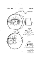
In the drawings: Figure l is a front elevation of a panoramic,
ornamental device according to the inventionwith portions broken away to show parts in sec- 20 tion;
Figure 2 is a cross-section along the line 2;-2 of Figure 1;
Figure 3 is a fragmentary cross-sectional view of a modification;
25 Figure 4 is a section taken along the line 44 of Figure 3;
Figure 5 is a fragmentary top plan View taken along the line 5-5 of Figure 4; and,
Figure 6 is a fragmentary top plan view taken 30 along the line BB of Figure 4.
Throughout the drawings the same reference characters are used to designate the same or analogous parts.
The invention is carried out by arranging the 35 picture or film within a closed casing and Which film can be rotated or rolled and unrolled so that parts of the film may be inspected through a window or a lens in the casing.
Referring in greater detail to the drawings:
40 The casing II] in the embodiment shown in the drawings has the configuration and arrangement of a terrestrial globe. The casing or globe In is rotatably mounted in the frame H. The frame I l is, in turn, rotatably mounted in the 45 ornamental support l2. In this manner, a universal bearing is provided for the casing I0. The support I2 is mounted on the base plate l3.
The ends of the frame H are bent inwardly to penetrate into diametrically opposite perfora- 50 tions in the globe which perforations serve the purpose of bearings to permit rotation of the globe.
Within the casing or globe I is mounted the rotatable frame I4 which is soldered or otherwise attached to the pivot I5 which projects, through the upper opening of the sphere. The pivot l5 also forms a sleeve or a bearing for the inwardly bent end of the frame ii.
The frame may be rotated manually by means of the thumb-nut it which is welded or soldered 5 or otherwise connected to the pivot IS. The frame M carries a picture or a film H which may comprise a multiplicity of scenes or views of a city or a tract of country. The film H is illuminated by the light admitted through the win- 10 dow it and may be inspected through the lens H] which, in the embodiment shown, has the configuration of an arrowpoint pointing toward the geographical location of the city of New York on the map shown on the globe. This lens may be inserted into the wall of the sphere simply by making an incision therein and bending the severed ends inwardly and over the lens as shown in Figure 2 of the drawings. The window l8 may be fastened on the opposite side in back of the film l! in similar manner.
The sphere or globe I0 is preferably made in two halves having over-lapping edges. In this manner, the picture or panorama mounted in the frame M may be removed and exchanged.
The ornamental support 12 which in the modification shown in the drawings has the shape of a trylon may be provided with decorative material 20 such as views of a city or tract of land to make the device suitable as a souvenir of the place in which the device was purchased.
The support 12 is preferably movably mounted on the base plate l3 by means of a slip-fit connection produced by the telescopic flange 2|.
In the modification shown in Figure 3 the rotatable frame for carrying the panoramic picture has been substituted by the spaced spindles 22 on which the picture film 23 may be wound and unwound, so that the portion of the film may be viewed through the lens IS. The film is illuminated by light admitted through the window [8 in the same manner as in the modification shown in Figures 1 and 2.
The spindles 22 are rotatably mounted on brackets 22a which in turn are mounted in the frame 22b. The frame 22b is supported within the casing 10. Each spindle is provided with a wheel 25 which frictionally engages the wheel 26. The wheel 25 is mounted on the rotatable bearing fitting 27 on the bracket 22a. The wheel 26 is provided with a stem 26a having a thumb-nut 28 outside of the casing H] by means of which the wheel 26 may be rotated. It will be understoodthat the rotation of the wheel 26 also rotates the wheels 25 to wind and unwind the film.
It will be understood that the device shown in Figures 1 and 2 as well as the device shown in Figures 3 to 6, inclusive, are operated simply by turning the nuts l6 and 28, respectively. As these nuts are turned a series of scenes or views will pass successively before the lens l9 so that they may be viewed by the spectator.
It will be understood that the invention is not necessarily limited to the exact embodiments illustrated in the drawings, but various modifications may be made within the scope of the appended claims:
What is claimed:
l. A panoramic device comprising a spherical casing representing a terrestrial globe, a support for said globe and means providing a universal bearing connecting said globe to saidsupport, a movable panoramic picture within said casing, means enabling inspection of said picture and means for moving said panoramic picture to pass the various views thereof before the eye of a spectator.
2. A panoramic device comprising a casing,
a rotatable frame within said casing, a panoramic picture supported in said frame, means for manually rotating said frame from the outside of said casing, means for illuminating said panoramic picture and means in said casing enabling inspection of said picture.
3. A panoramic device comprising a casing representing a terrestrial globe, a support for said casing and means providing a universal connection connecting said globe to said support, a rotatable frame within said globe, a panoramic picture mounted in said frame, means for manually rotating said frame from the outside of said globe, a window in the wall of said casing for illuminating said panoramic picture, and means in said casing enabling inspection of said picture.
4. A panoramic device comprising a spherical casing representing a terrestrial globe, a support for said globe and means providinga universal bearing connecting said globe to said support, a
panoramic picture Within said casing and means enabling inspection of said picture. JOSEPH CRESPO.
Priority Applications (1)
| Application Number | Priority Date | Filing Date | Title |
|---|---|---|---|
| US257050A US2182334A (en) | 1939-02-18 | 1939-02-18 | Panoramic device |
Applications Claiming Priority (1)
| Application Number | Priority Date | Filing Date | Title |
|---|---|---|---|
| US257050A US2182334A (en) | 1939-02-18 | 1939-02-18 | Panoramic device |
Publications (1)
| Publication Number | Publication Date |
|---|---|
| US2182334A true US2182334A (en) | 1939-12-05 |
Family
ID=22974680
Family Applications (1)
| Application Number | Title | Priority Date | Filing Date |
|---|---|---|---|
| US257050A Expired - Lifetime US2182334A (en) | 1939-02-18 | 1939-02-18 | Panoramic device |
Country Status (1)
| Country | Link |
|---|---|
| US (1) | US2182334A (en) |
Cited By (25)
| Publication number | Priority date | Publication date | Assignee | Title |
|---|---|---|---|---|
| US2492691A (en) * | 1946-11-25 | 1949-12-27 | William H Dietz | Illuminated world globe |
| US2549658A (en) * | 1946-10-26 | 1951-04-17 | Louis H Blythe | Display device |
| US3086299A (en) * | 1958-11-19 | 1963-04-23 | Edward D Wilkerson | Educational device for demonstrating earth globe rotation |
| US4584212A (en) * | 1980-01-29 | 1986-04-22 | Toan Klein | Decorative glass sculpture and method of manufacture |
| US4790756A (en) * | 1987-09-29 | 1988-12-13 | The Quaker Oats Company | World globe geographic area viewer |
| US5153716A (en) * | 1988-12-14 | 1992-10-06 | Horizonscan Inc. | Panoramic interactive system |
| US5686705A (en) * | 1996-02-15 | 1997-11-11 | Explore Technologies, Inc. | Surface position location system and method |
| US5877458A (en) * | 1996-02-15 | 1999-03-02 | Kke/Explore Acquisition Corp. | Surface position location system and method |
| US20030198928A1 (en) * | 2000-04-27 | 2003-10-23 | Leapfrog Enterprises, Inc. | Print media receiving unit including platform and print media |
| USRE38286E1 (en) | 1996-02-15 | 2003-10-28 | Leapfrog Enterprises, Inc. | Surface position location system and method |
| US6661405B1 (en) | 2000-04-27 | 2003-12-09 | Leapfrog Enterprises, Inc. | Electrographic position location apparatus and method |
| US20040063078A1 (en) * | 2002-09-30 | 2004-04-01 | Marcus Brian I. | Electronic educational toy appliance |
| US20040104890A1 (en) * | 2002-09-05 | 2004-06-03 | Leapfrog Enterprises, Inc. | Compact book and apparatus using print media |
| US20040142308A1 (en) * | 1995-12-29 | 2004-07-22 | Marcus Brian I. | Electronic educational toy appliance having a touch sensitive surface |
| US20040140966A1 (en) * | 2001-06-20 | 2004-07-22 | Leapfrog Enterprises, Inc. | Interactive apparatus using print media |
| US20040246211A1 (en) * | 2003-06-09 | 2004-12-09 | Leapfrog Enterprises, Inc. | Writing stylus for electrographic position location apparatus |
| US20050082359A1 (en) * | 2000-04-27 | 2005-04-21 | James Marggraff | Print media information systems and methods |
| US20060080609A1 (en) * | 2004-03-17 | 2006-04-13 | James Marggraff | Method and device for audibly instructing a user to interact with a function |
| US20070097100A1 (en) * | 2005-11-01 | 2007-05-03 | James Marggraff | Method and system for invoking computer functionality by interaction with dynamically generated interface regions of a writing surface |
| USRE39881E1 (en) | 1996-02-15 | 2007-10-16 | Leapfrog Enterprises, Inc. | Surface position location system and method |
| US7831933B2 (en) | 2004-03-17 | 2010-11-09 | Leapfrog Enterprises, Inc. | Method and system for implementing a user interface for a device employing written graphical elements |
| US7916124B1 (en) | 2001-06-20 | 2011-03-29 | Leapfrog Enterprises, Inc. | Interactive apparatus using print media |
| US7922099B1 (en) | 2005-07-29 | 2011-04-12 | Leapfrog Enterprises, Inc. | System and method for associating content with an image bearing surface |
| US8261967B1 (en) | 2006-07-19 | 2012-09-11 | Leapfrog Enterprises, Inc. | Techniques for interactively coupling electronic content with printed media |
| US8599143B1 (en) | 2006-02-06 | 2013-12-03 | Leapfrog Enterprises, Inc. | Switch configuration for detecting writing pressure in a writing device |
-
1939
- 1939-02-18 US US257050A patent/US2182334A/en not_active Expired - Lifetime
Cited By (51)
| Publication number | Priority date | Publication date | Assignee | Title |
|---|---|---|---|---|
| US2549658A (en) * | 1946-10-26 | 1951-04-17 | Louis H Blythe | Display device |
| US2492691A (en) * | 1946-11-25 | 1949-12-27 | William H Dietz | Illuminated world globe |
| US3086299A (en) * | 1958-11-19 | 1963-04-23 | Edward D Wilkerson | Educational device for demonstrating earth globe rotation |
| US4584212A (en) * | 1980-01-29 | 1986-04-22 | Toan Klein | Decorative glass sculpture and method of manufacture |
| US4790756A (en) * | 1987-09-29 | 1988-12-13 | The Quaker Oats Company | World globe geographic area viewer |
| US5153716A (en) * | 1988-12-14 | 1992-10-06 | Horizonscan Inc. | Panoramic interactive system |
| US7217135B2 (en) | 1995-12-29 | 2007-05-15 | Tinkers & Chance | Electronic educational toy having a contact-sensitive display screen |
| US20040142311A1 (en) * | 1995-12-29 | 2004-07-22 | Marcus Brian I. | Computer software and portable memory for an electronic educational toy having a contact sensitive display screen |
| US7006786B2 (en) | 1995-12-29 | 2006-02-28 | Tinkers & Chance | Computer software and portable memory for an electronic educational toy |
| US20040146843A1 (en) * | 1995-12-29 | 2004-07-29 | Marcus Brian I. | Electronic educational toy having a contact-sensitive display screen |
| US20040146844A1 (en) * | 1995-12-29 | 2004-07-29 | Marcus Brian I. | Electronic educational toy having a contact-sensitive display screen |
| US7214066B2 (en) | 1995-12-29 | 2007-05-08 | Tinkers & Chance | Computer software and portable memory for an electronic educational toy having a contact sensitive display screen |
| US7040898B2 (en) | 1995-12-29 | 2006-05-09 | Tinkers & Chance | Computer software and portable memory for an electronic educational toy |
| US7029283B2 (en) | 1995-12-29 | 2006-04-18 | Tinkers & Chance | Electronic educational toy |
| US20040142308A1 (en) * | 1995-12-29 | 2004-07-22 | Marcus Brian I. | Electronic educational toy appliance having a touch sensitive surface |
| US20040142309A1 (en) * | 1995-12-29 | 2004-07-22 | Marcus Brian I. | Computer software and portable memory for an electronic educational toy having a touch sensitive surface |
| US7018213B2 (en) | 1995-12-29 | 2006-03-28 | Tinkers & Chance | Electronic educational toy teaching letters words, numbers and pictures |
| US20040142310A1 (en) * | 1995-12-29 | 2004-07-22 | Marcus Brian I. | Electronic educational toy appliance having a touch sensitive surface teaching letters words and numbers |
| US5877458A (en) * | 1996-02-15 | 1999-03-02 | Kke/Explore Acquisition Corp. | Surface position location system and method |
| US5686705A (en) * | 1996-02-15 | 1997-11-11 | Explore Technologies, Inc. | Surface position location system and method |
| USRE38286E1 (en) | 1996-02-15 | 2003-10-28 | Leapfrog Enterprises, Inc. | Surface position location system and method |
| USRE39881E1 (en) | 1996-02-15 | 2007-10-16 | Leapfrog Enterprises, Inc. | Surface position location system and method |
| US20050219591A1 (en) * | 2000-04-27 | 2005-10-06 | James Marggraff | Print media information systems and methods |
| US7120386B1 (en) | 2000-04-27 | 2006-10-10 | Leapfrog Enterprises, Inc. | Print media receiving unit including platform and print media |
| US20030198928A1 (en) * | 2000-04-27 | 2003-10-23 | Leapfrog Enterprises, Inc. | Print media receiving unit including platform and print media |
| US6661405B1 (en) | 2000-04-27 | 2003-12-09 | Leapfrog Enterprises, Inc. | Electrographic position location apparatus and method |
| US6668156B2 (en) | 2000-04-27 | 2003-12-23 | Leapfrog Enterprises, Inc. | Print media receiving unit including platform and print media |
| US7499036B2 (en) | 2000-04-27 | 2009-03-03 | Leapfrog Enterprises, Inc. | Electrographic position location apparatus and method |
| US7139523B1 (en) | 2000-04-27 | 2006-11-21 | Leapfrog Enterprises, Inc. | Print media receiving unit including platform and print media |
| US7039355B2 (en) | 2000-04-27 | 2006-05-02 | Leapfrog Enterprises, Inc. | Print media receiving unit including platform and print media |
| US20050082359A1 (en) * | 2000-04-27 | 2005-04-21 | James Marggraff | Print media information systems and methods |
| US7557939B2 (en) | 2000-04-27 | 2009-07-07 | Leapfrog Enterprises, Inc. | Print media information systems and methods |
| US7299971B2 (en) | 2000-04-27 | 2007-11-27 | Leapfrog Enterprises, Inc. | Print media information systems and methods |
| US7916124B1 (en) | 2001-06-20 | 2011-03-29 | Leapfrog Enterprises, Inc. | Interactive apparatus using print media |
| US20040140966A1 (en) * | 2001-06-20 | 2004-07-22 | Leapfrog Enterprises, Inc. | Interactive apparatus using print media |
| US8952887B1 (en) | 2001-06-20 | 2015-02-10 | Leapfrog Enterprises, Inc. | Interactive references to related application |
| US6985139B2 (en) | 2001-06-20 | 2006-01-10 | Leapfrog Enterprises, Inc. | Interactive apparatus using print media |
| US20040104890A1 (en) * | 2002-09-05 | 2004-06-03 | Leapfrog Enterprises, Inc. | Compact book and apparatus using print media |
| US20040063078A1 (en) * | 2002-09-30 | 2004-04-01 | Marcus Brian I. | Electronic educational toy appliance |
| US20080043001A1 (en) * | 2003-06-09 | 2008-02-21 | Michael Perkins | Writing stylus |
| US7068262B2 (en) | 2003-06-09 | 2006-06-27 | Leapfrog Enterprises, Inc. | Writing stylus for electrographic position location apparatus |
| US7567242B2 (en) | 2003-06-09 | 2009-07-28 | Leapfrog Enterprises, Inc. | Writing stylus |
| US20040246211A1 (en) * | 2003-06-09 | 2004-12-09 | Leapfrog Enterprises, Inc. | Writing stylus for electrographic position location apparatus |
| US7831933B2 (en) | 2004-03-17 | 2010-11-09 | Leapfrog Enterprises, Inc. | Method and system for implementing a user interface for a device employing written graphical elements |
| US7853193B2 (en) | 2004-03-17 | 2010-12-14 | Leapfrog Enterprises, Inc. | Method and device for audibly instructing a user to interact with a function |
| US20060080609A1 (en) * | 2004-03-17 | 2006-04-13 | James Marggraff | Method and device for audibly instructing a user to interact with a function |
| US7922099B1 (en) | 2005-07-29 | 2011-04-12 | Leapfrog Enterprises, Inc. | System and method for associating content with an image bearing surface |
| US20070097100A1 (en) * | 2005-11-01 | 2007-05-03 | James Marggraff | Method and system for invoking computer functionality by interaction with dynamically generated interface regions of a writing surface |
| US7936339B2 (en) | 2005-11-01 | 2011-05-03 | Leapfrog Enterprises, Inc. | Method and system for invoking computer functionality by interaction with dynamically generated interface regions of a writing surface |
| US8599143B1 (en) | 2006-02-06 | 2013-12-03 | Leapfrog Enterprises, Inc. | Switch configuration for detecting writing pressure in a writing device |
| US8261967B1 (en) | 2006-07-19 | 2012-09-11 | Leapfrog Enterprises, Inc. | Techniques for interactively coupling electronic content with printed media |
Similar Documents
| Publication | Publication Date | Title |
|---|---|---|
| US2182334A (en) | Panoramic device | |
| US1959601A (en) | Chronological instrument | |
| US2632359A (en) | Planetarium | |
| US2204435A (en) | Animated display apparatus | |
| US2152424A (en) | Designoscope | |
| US5212874A (en) | Three-dimensional drawing device | |
| US3707786A (en) | Method and means of presenting a planetarium display | |
| US2492785A (en) | Terrestrial globe | |
| US3089259A (en) | Miniature solar system displays | |
| US5038482A (en) | Three-dimensional drawing device | |
| US3251143A (en) | Planetarium | |
| US2954723A (en) | Kaleidoscopic advertising display | |
| US2797500A (en) | Educational devices | |
| US1524627A (en) | Display device | |
| CN206312533U (en) | Rimless rolling advertisement lamp box | |
| US1899788A (en) | Animated wind toy | |
| US3718992A (en) | Self-contained planetarium | |
| US1289849A (en) | Method of teaching and illustrating. | |
| CN100590680C (en) | Sunshine earth phenomenon instrument | |
| US1619565A (en) | Aerial advertiser | |
| US1567471A (en) | Advertising device | |
| US2492691A (en) | Illuminated world globe | |
| US1890408A (en) | Radio receiving set | |
| CN215814797U (en) | Earth rotation plane presentation device | |
| US2844894A (en) | Display device |