US2024950A - Method and apparatus for making cast metal containers - Google Patents
Method and apparatus for making cast metal containers Download PDFInfo
- Publication number
- US2024950A US2024950A US694711A US69471133A US2024950A US 2024950 A US2024950 A US 2024950A US 694711 A US694711 A US 694711A US 69471133 A US69471133 A US 69471133A US 2024950 A US2024950 A US 2024950A
- Authority
- US
- United States
- Prior art keywords
- core
- mold
- barrel
- metal
- casting
- Prior art date
- Legal status (The legal status is an assumption and is not a legal conclusion. Google has not performed a legal analysis and makes no representation as to the accuracy of the status listed.)
- Expired - Lifetime
Links
Images
Classifications
-
- B—PERFORMING OPERATIONS; TRANSPORTING
- B22—CASTING; POWDER METALLURGY
- B22C—FOUNDRY MOULDING
- B22C9/00—Moulds or cores; Moulding processes
- B22C9/22—Moulds for peculiarly-shaped castings
- B22C9/24—Moulds for peculiarly-shaped castings for hollow articles
Definitions
- This invention asindicated, relates to the method and apparatus for making cast metal containers.
- This application is a division of application Serial No. 685,955, Cast metal container and method for making the same, filed August 19, 1933, which was issued on Oct. 24, 1933 as Patent No. 1,932,325.
- the present invention also comprises an improvement over the subject matter set forth in an application heretofore filed on July 5, 1933,
- the entire container may be made as a substantially integral structure by first independently forming one head member of the container, illustrated here as abeer barrel, with a marginal portion suitably shaped to interlock with the metal of the body portion of the barrel,
- integra is used to define a structure In this case the (Cl. 22-2ii3) wherein the parts are united by fusion within the mold and/or shrinkage within the mold of one part upon the other. 7
- the proposed method provides a means for manufacturing such articles on a high speed production basis and with great economy in carrying out the operations, as well as dependable results in producing a satlsl5 factory product. It is to be understood that when the term aluminum is used in the claims it is intended to include alloys thereof as well as pure aluminum metal.
- the method outlined is adapted for use with 20 various metals and combinations of metals and 4 with many types of containers, particularly those made in several stages and having a portion of the structure which must be permanently secured to the remaining portion or" the structure, and 2 5 wherein the shrinkage of the external structure upon the internal structure may be utilized in securing a permanent and satisfactory union of the several parts.
- the invention contemplates the 30 production of a container formed substantially as an integral structure with very restricted openings into the interior thereof and yet having wall thickness and internal structural elements substantially of predetermined size and quality. 35
- the invention also contemplates the production of the container or like article in either a mold formed of metal or partially of metal and preferably of the type designated permanent or semipermanent molds, or in a green sand mold or 40 mold formed partially of green sand and partially of baked sand elements.
- the invention also contemplates the series of steps embodied in the formation of the core and the assembling of the same with the elements of 45 a metal mold in whole or in part, or with the elements of a sand molding structure, as well as the removal of the core from the completed structure and the removal of the excess metal from the completed structure. 50
- the principal object of the present invention is to provide an improved method of casting containers and the like in a two-stage operation as integral or substantially integral structures with accurate conformity to the matter of structural 55 dimensions and strength and with economy of time and labor in carrying out such production.
- Another object of the invention is to provide containers and the like formed of cast metal wherein a portion ofthe structure is associated with the remaining portion of the structure in substantially integral permanent relation.
- a further object of the invention is to provide a method of using a mold formed wholly of metal or partly of metal and partly of other material for producing a container or the like, wherein the core embodies a part of the structure of such container or like article.
- a further object of the invention is to provide a method of utilizing a separable core box and separable mold members in a casting operation whereby green sand may be utilized in forming containers or like articles which are required to be of accurate dimensions and adequate strength without undue thickness of elements and variations from shapes of the articles being manufactured by other methods and yet adapted for high speed production on a quantity basis.
- Another object of the invention is to provide a core member for casting formed of green sand and having embedded therein as part of the core structure a portion of the finished container or like article and permitting such interposed portion of the core to become united with the remaining portion of the container in permanent union as an integral structure without in any way detracting from its service as a structural element of such container or the conformity of the container, particularly when in the form of a beer barrel, to conventional requirements and Without detracting from its appearance.
- Figure 1 is a top plan View of a permanent mold embodying the principles of the invention, portions of the base plate being cut away;
- Figure 2 is a central vertical sectional view of the structure shown in Figure 1, taken along the parting plane of the mold halves;
- V Figure 4 is a top plan view of the part shown in Figure 3;
- Figure 5 is a central vertical sectional view of the structure shown in Figure 3 when inverted to its final position for the completion of the remaining portion of the core;
- Figure 6 is a top plan View of the structure shown in Figure 5;
- FIG. 7 is a view similar to Figure 5, with the upper portion of the core box in place;
- Figure 8 is a top plan view of the structure shown in Figure 7;
- Figure 9 is a fragmentary sectional view show ing a modified form of baked sand core for one head portion of the mold
- Figure 10 is a central vertical sectional view, taken along the plane of the sprues, showing the core illustrated in Figures 2 and '7 in assembled relation with the cope and drag sections of a green sand flask;
- Figure 11 is a side elevation of the article produced in the mold shown in Figure 2, with the attached sprues, runners and risers;
- Figure 12 is a fragmentary plan view, partly in section, taken along the line l2l2, shown in Figure 11, looking in the direction of the arrows;
- Figures 13 and 14 are sectional views, taken along the lines I 3-! 3 and MM, respectively, shown in Figure 11, looking in the direction of the arrows;
- Figure 15 is a fragmentary view of a corner portion of a structure similar to that shown in Figure 11, with a modified type of metal feeding passageways.
- the movable side members of the permanent mold are formed of suitable metal and are each provided at their rearward ends with pairs of hinges permitting them to be moved toward each other and suitably secured at their forward edges so as to form the casting cavity, and to be swung outwardly about said bearing pin 8 so as to free the casting after the pouring operation is completed.
- two movable mold sections are provided on each side of the central vertical parting plane of the mold, the lower sections I2 being of less vertical height than the upper sections l3.
- the left hand lower section l2 if viewed from the side of the mold opposite the bearing pin, is formed with apertured lugs l 4, I5, pivotally engaged upon the bearing pin 8, and its companion lower member E2 on the right hand side is formed with apertured lugs l6, l1, engaged upon said bearing pin and alternately spaced above the lugs M, [5 of the companion member so as to perengaged about the bearing pin 8,-the lower. lug2
- Any suitable fastening means such as conventional clamping yokes and wedges (not shown), may be used to secure the front edges of the mold in tightly clamped relation.
- the movable mold sections when held in closed position, will present a casting cavity 23 ofthe conventional shape of a beer barrel, the lower portion terminating at a point slightly above the upper surface ofthe base plate, the end and inner flange portions of said casting cavity being formed by a core print 24 and a sand core 25 in conjunction with the lower portion of the movable mold sections 12.
- the upper portion of the casting cavity is formed preferably by means of a baked sand core section 26 supported in a recess formed between the upper movable mold sections 13 and having upwardly and outwardly beveled sides 21 extending about the greater portion of the circumference of the mold halves.
- a riser cavity 28 is provided, said riser cavity being formed partially in the baked sand core and partially in the movable upper mold sections, and being wider adjacent its upper portion than adjacent its point of communication with the casting cavity.
- the meeting faces of the upper mold sections K3 are each provided with a. sprue cavity 29 preferably bent first in a direction toward the cavity and then away therefrom and then again toward the cavity and away therefrom to a point of discharge into a feeder cavity 3
- An upwardly directed feeder passageway 34 is provided to supply metal from the sprue 29 in an upward direction to the upper margin of the casting cavity adjacent the point of the merging of the riser cavity 28 with the cavity 35 for forming the upper flange or chime of the barrel.
- the casting cavity is defined between the movable mold members IZ and I3 and the core 36, the detailed construction of which will be presently described.
- Theupper end of the core terminates short of the baked sand core member 26 providing an upper section of the casting cavity 3'5 within which the upper head portion of the barrel is formed:
- the other head member of the barrel is not formed simultaneously with the body portion of the barrel and the integral head portion, but is preformed and is united with the bodyportion of the barrel-when the metal is poured into the mold. It is to be understood, however, that in place of supplying one preformed head, two preformed heads may be utilized and a core may be utilized if desired, and only the body portion of the barrel need be formed in the casting cavity in such case, the heads becoming united with the body portion upon the cooling of the casting and the sand core being shaken from the interior of the barrel, as will be hereinafter described.
- the upper core portion of the mold maybe formed in the manner shown in Figure 9.
- with beveled upper and lower portions meeting along the central circumferential line may be formed of some suitable material such as aluminum or iron or steel, within which a portion of the baked sand core 42 is embedded, the lower portion of the baked sand core 43 having an outwardly flared portion to form the upstanding flanged areaabout the integral head of the barrel.
- the casting cavity outwardly of said upstanding flange portion is formed with an annular channel 44 which is fed by the feeder passageway 45 extending upwardly On each side of the mold at the parting plane from thesprue.
- the annular member Al is suitably shaped to be received within a beveled recess in the upper movable mold sections and when so supported provides the transverse casting cavity 41 to form the integral head of the barrel.
- the annular channel 44 produces an outwardly projecting rib upon the completed casting which may be removed in any suitable manner, such as by chipping, or grinding, or the like.
- Such annular channel 44 serves to supply the upstanding flange portion of the barrel with sumcient metal to prevent shrinkage defects atthe top bead formed on the barrel flange, andto facilitate the casting operation.
- the horizontal parting plane of the movable side members of the mold is below the center line of the mold in order to provide for the positioning of the bung hole on such center line free ofthe fins and other elements which would detract from the strength and appearance of the barrel at such point, if formed at the parting plane.
- the bung hole is formed by means of a baked sand plug 48 seated in a socket 49 formed by a core print 60 at a point where the core is flattened slightly to produce a flattened wall area 50 on one side of the barrel.
- the permanent mold just described is adapted to form the outer surface of the barrel, as well as the projecting end portions or chimes thereof beyond the respective heads, and in the preferred form of construction to form the outer surface of one head member.
- the other head member in the preferred form of construction is preformed and is embodied in the core which will now be described.
- the core is formed in the core box, as shown in Figure 7, having a lower section formed of two halves 5
- the core box may be formed of wood or metal, but as shown is formed of aluminum.
- are provided with lateral extensions 54 adjacent their upper portions providing vertical flanges for clamping the sections together and horizontal flanges providing a socket for an alining pin 55 for bringing the upper and lower sections into registry, as will be hereinafter explained.
- an extension base plate 55 is provided, said plate at the parting plane of the halves being provided with upward extension 57 for clamping said halves together.
- the single upper section of the core box 53 is formed at its lower portion with an annular extension 58 adapted to rest upon the horizontal flange of the two-part lower section when assembled, said extension being provided with apertures at the parting plane to receive the alining pins 55 hereto-fore referred to.
- the upper edge portion 59 of the upper section 53 of the core box terminates slightly below the top of the core cavity and is formed with a cylindrical outer face 6 I, serving as a guide for the annular sweep support 62 adjustably supporting the inwardly directed sweeps 53- by means of bracket arms 65.
- the annular sweep support 62 is formed with a flat bearing face 65 at its under side which rests against rollers 66 rotatably' mounted upon horizontal pins 61 secured to the enlarged upper edge portion of the upper section 59; Four such rollers are shown and the annular sweep support accordingly is firmly supported upon the upper portion of the flask so as to shape the upper portion of the core uniformly as each core is completed.
- the interior of the core box provides a cavity of the general configuration of a beer barrel throughout the main body portion thereof, but may be provided with annular enlargements 68, 69 at intermediate points of each half so as to formslight depressions around the core which will provide for beveled ribs on the interior of the finished casting at points intermediate of each half a section thereof.
- the core box is adapted to receive the preformed head member which, it will be noted,
- the lower core sections are formed with an enlargement 12 on the inner face having an annular notch 1-3 to receive the extensions of the preformed head member of the barrel.
- the lower portion of the core box is shaped to provide for a recess 14 to form the bead on the projecting flange portion or chime of the barrel and beneath such portion has an opening with beveled sides 15 to receive the print ring 16 formed as a flange upon a core frame 11 in the shape of a spoked wheel.
- An upstanding boss 18 is formed centrally of the frame, said boss being centrally apertured in alinement with an opening 19 in the precast head member.
- the opening 19 - is preferably a beveled opening formed as part of a filling fixture terminal 8
- Such filling fixture terminal is of conventional form and forms no part of the present invention.
- the upstanding boss 18 centrally of the core frame 11 is provided with an enlarged aperture 82 adjacent its outer portion and with a screw threaded section 83 of smaller diameter at its free end to receive the screw threaded end 84 of an arbor 85 which is inserted centrally of the core box, as will be hereinafter explained.
- the arbor intermediatethe screw-threaded portion and themain body portion is formed with a shank 86 extending through the central opening 19 of the filling terminal 8! in the precast head.
- the core frame. 11 is provided with a plurality of standards 81 at points spaced from the central upstanding boss 18 and of a height adapted to engage with their free ends the outer surface of the precast head which, as has been indicated, rests centrally against the. free end of the upstanding boss.
- the arbor is suitably tapered to provide for its easy Withdrawal from the core and its upper end is formed with a tapered portion against the lower area of which the inner ends of the sweeps B3 engage.
- a cross bar 88 is engaged through a transverse aperture 89 in the upper end of the arbor to provide a means for lifting the core and placing the same in either the permanent mold or the green sand mold, as may be required.
- the core is formed in several stages, the first .step, as shown in Figures 3 and 4, requiring the jecting upper head plate 101engaged in the annular notch 13 and with the core frame 11 bearing against said plate immediately above the same. Green sand is then rammed into place through the spokes of r the frame support to form the lower portion SI of the core, the excess sand being struck off above head plate and in the upstanding boss 18 of the core frame support and screwed into firm engagement with the screw-threaded socket 83.
- the arbor is held in a central position by means of the guide bar 92 which is provided with a central notch 93 to engage the arbor and is held at its ends by the alining pins 55.
- the lower portion of the core box is then ready for the ramming of the lower section 94 of the core and when the core box is filled, the guide bar 92 is removed and the upper section of the core box is fitted into place on the lower core box sections, the alining pins 55 bringing the same into proper'alinement therewith.
- the assembled core box clamped in conventional manner is then ready for filling to the top which is accomplished by ramming the upper portion 95 of the core with green sand and thereupon placing the support for the sweeps about the upper edge and rotating the same to suitably form the top surface of the cor
- the core box is then removed from the core and the core is lifted bodily by means of the arbor and engaged in the recess in the base plate of the permanent mold, when it is desired to use that type of mold to form the casting, or, is engaged in a like recess formed in the'drag of a green sand mold to receive the print at the base of the core, as will presently be described.
- the apparatus With the mold assembled, as shown in Figure 2 of the drawings, with movable sides of the permanent mold tightly clamped to each other in conventional manner, the apparatus is ready for the casting operation which is carried on preferably by pouring the metal through each of the sprues 29.
- the metal will flow down the sinuous passageways of said sprues with some retardation of the rate of flow and will enter the circumferential runner about the structure and flow through the gates into the casting cavity and will at first flow downwardly about the margins of the precast head enveloping such marginal edges and to a certain extent fusing therewith and shrinking thereupon to form an integral structure.
- the metal in the casting cavity rises, it will form the main body portion of the barrel and as it reaches the upper portion of the barrel will form the profiange thereof, such flange being adequately supplied by metal through the upwardly directed feeder passageways communicating with the respective sprues and from the risers communicating with the upper margins of the projecting flange adjacent the opposite sides of the parting plane of the mold.
- the mold is thrown open and the excess metal is broken from or otherwise removed from the surface of the casting.
- the casting before such metal is removed, will exhibit the structural features shown in Figure 11, wherein the main body portion of the barrel Illl is surrounded at a point slightly below its center line by a circumferential runner I02 connected at intervals by narrow gate webs I03 with the outer surface of the casting.
- the sprue metal I04 will be in sinuous form and the risers I05 will be connected with the sprues by the feeder ....ure 10 is used, the drag portion [2! metal 106 formed by the upwardly directed passageways.
- the core frame and its adherent sand is removed and the baked sand core is removed from the end of the casting and the main body of the core is then removed through the lateral bung hole by shaking, washing, or by means of an air blast, as may be found most convenient.
- the finished structure provides a barrel having light weight and fine grained texture on its inner and outer surfaces.
- the inner surface of the barrel may be coated with pitch or any of the usual lining materials utilized for containers for malt beverages and the like. It also has the advantage of holding the contents at the required temperature with a lesser amount of refrigerating agent, and lends itself readily to cleansing and pasteurizing operations. It further has the advantage of maintaining the quality of the contents notwithstanding wide variations in temperature above and below those found injurious to the contents of such liquids in other containers.
- the casting cavity may be modified as has been explained in connection with the description of Figure 9, to form a casting of the type shown in Figure 15, wherein a circumferential runner III is formed about the outer margin of the upwardly projecting flange and supplies adequate metal to such part through the upwardly directed feeder passageways 45 communicating with the sprues H3.
- the remaining portion of the barrel H t will be substantially like that shown in Figure 11.
- the cope section of the mold I23 is filled when in inverted position in the usual manner and is provided with a recess l2 with beveled margins to receive the baked sand core I25 for forming the outer surface of the integral eead portion of the barrel, as well as the projecting flange portions of the barrel, such baked sand core being secured by means of suitable supports shown as wires [26 extending through the cope section of the mold and secured in conventional manner by means of cross wires I21 or the like to maintain such baked sand core in suitable position at the top of the casting cavity of the cope.
- the sprue passageways utilized in the sand mold are shown in the form of straight passageways I28 extending from the top of the cope downwardly to the parting plane of the cope and drag sections of the mold which are preferably located at the central horizontal plane of the casting cavity.
- the sprue passageways are downwardly tapered and the lower portion of the cope is formed with a circumferential runner passageway l29 communicating with a thin gate l3l which may be continuous about the casting cavity or similar to the gate shown in Figure 12, for the permanent mold wherein it is interrupted at intervals about the circumference of the casting cavity, the intervals lfilil between the gates being somewhat greater opposite the lower ends of the sprue passageways in order to divert the metal laterally preliminary to its entering the casting cavity.
- the sand core when finished as shown in Figure '7, having the plug in position for forming the bung hole and shaped to provide a somewhat thickened area about the bung hole as heretofore described, after the removal of the core box is seated within the drag section iii of the green 5 sand mold.
- the arbor 85 of the core is then unscrewed and withdrawn and the central opening left in said core is filled with sand to the top of the main body portion of the core.
- the cope section 923 of the green sand mold is then placed 10 in position, the assembled structure then appearing as shown in Figure 10 of the drawings.
- the metal is poured preferably simultaneously down each of the sprues E28 and the margins of the precast head "it are partially fused and integrally 15 united with the metal introduced into the casting cavity. As the metal rises in the mold cavity it forms the structure substantially identical with the cavity shown in Figure 10 of the drawings.
- the cope 20 section is removed and thereafter the cast barrel is disengaged from the drag section and the excess metal is broken away from the exterior of the casting and the core sections at the ends of the barrel are removed therefrom and the sand 25 core within the interior of the barrel is removed by shaking,washing, or by means of an air blast or other convenient methods, through the bung hole at the side of the barrel and the opening at the end thereof.
- the article finished in the green sand mold will exhibit substantially all the characteristics of the article heretofore described as constructed in the permanent mold, but may have slightly less fine grain about the surface thereof, and does not lend itself to as rapid rate of production as in the metal. mold.
- the thin gate provided in the green sand mold serves to prevent more highly oxidized and less freely flowing metal from entering the casting cavity and thus insures a high 40 quality of metal within the casting cavity which will accurately conform to the shape of such cavity and form a casting free of irregularities and defects which might otherwise enter the article through the metal feeding passageways.
- a method of casting a beer barrel of conventional outline from aluminum or aluminum alloys which includes the steps of preforming one head member of the barrel in a separate casting operation with an extension marginal area about said head member of a size to project into the casting cavity for the main body portion of the barrel, forming a core for the barrel of green sand in a separable core box with a print for the bung hole, and with the preformed head member embedded in said core in spaced relation to the end of said core with the extension marginal area of said head projecting outwardly from said core a distance sufficient to bring the same at a point substantially centrally of the casting cavity, assembling the sections of the mold upon said core, pouring the metal for the body portion of the barrel together with the integral head section thereof, whereby the flange portions of the preformed head member will be surrounded by the molten metal of the body portion of the barrel and will unite and shrink into close union there- 16 with to form substantially an integral structure, and thereafter removing the interior portion of said sand core through the bung hole provided in the
- a method of casting substantially closed containers having side walls and integrally united heads which includes the steps of preforming one head member with a marginal extension provid- A ing an enlarged circumferential bead, in a preliminary casting operation, providing sections of the' mold for the remaining structure, forming the core in a separable core box with the preformed head member embedded in said core and with its marginal extensions projecting therefrom, with the main body portion of the core above the same and a supporting print and core portion below the same, assembling the core with the mold members with the supporting print in the drag member of the mold and with the enlarged circumferential bead of the head member margins projecting into the casting cavity, providing an outer core for forming the integral head member, pouring the'metal into the casting cavity intermediate the core and assembled mold sections, whereby the metal in the casting cavity will engage about and shrink upon the marginal extensions of the head member, and thereafter removing said core from said completed casting.
- a method of casting a beer barrel of conventional outline from aluminum or aluminum alloys which includes the steps of preforming one head member of the barrel in a separate casting operation with an extension marginal area about said head member of a size to project it into the casting cavity for the main body portion of the barrel, forming a core for the barrel of green sand in a separable core box with a print for the bung hole, and with the preformed head member embedded in said core in spaced relation to the end of said core with the extension marginal area of said headprojecting outwardly from said core a distance sufiicient to bring the same at a point substantially centrally of the casting cavity, and with a core section and supporting print beneath said head member, providing an outer core for the integral head member, assembling the sections of the mold upon said cores, pouring the metal for the body portion of the 4 barrel together with the integral head section thereof, whereby the extension portions of the preformed head member will be surrounded by the molten metal of the body portion of the barrel and will unite and shrink into close union 5 therewith
- An apparatus for forming cast aluminum beer barrels which comprises a base plate, a recess in said base plate to receive a core supporting print, a plurality of movable metallic mold members supported onrsaid base plate and adapted to be moved into close relation above the same to provide a casting cavity, a sand core embodying a portion of said container wall with the margins thereof projecting into the casting cavity, extending upwardly from said core supporting print, a core plug for forming a bung hole supported in said core and an outer core supported in spaced relation to said first named core to form a portion of the outer surface of said barrel.
- An apparatus for forming cast aluminum beer barrels which comprises a base plate, a recess in said base plate to receive a core supporting print, a bearing pin rigidly secured to said base plate rearwardly of said recess, a plurality o1 horizontally movable mold sections pivotally mounted on said bearing pin and disposed in pairs on each side of said recess, the lowermost of each pair slidingly supported on said base plate, and a sand core supported'on a print engaged in said recess in the base plate and having embodied in its structure a precast head member for said barrel supported in slightly spaced relaber for said barrel supported'on said baked sand core member and a green sand core member supported on said precast head member, a plurality of separable metal mold members having a 25 vertical parting plane and a substantially centrally positioned horizontal parting plane adapted to be spaced about said core member to provide a casting cavity, and an upper core member supported in said mold members in spaced relation to said first-named core to complete the upper
- An apparatus for forming cast aluminum barrels having in combination a base plate, a recess in said base plate to receive a core supporting print, a core having a core print at its bottom portion, a baked sandcore member associated with said core print, a precast head member for said barrel supported on said baked sand core member and a green sand core member Sup- 40 gate formed in one surface of said mold mem- 5o bers at the horizontal parting plane, a circumferential runner passageway outwardly of said gate and communicating therewith, and a sprue passageway in the vertical parting plane of said ,7
- mold members extending from the upper portion of said mold to said runner passageway.
- An apparatus for forming cast aluminum barrels having in combination a base plate, a
- a core supporting print a core having a core print at its bottom portion, a baked sand core member associated with said core print, a precast head member for said barrel supported on said baked sand core member and a green sand core 'member supported on said precast head member, a plurality of separable metal mold members having a vertical parting plane and a substantially centrally positioned horizontal parting plane adapted to be spaced about said core member to provide a casting cavity, an upper core member supported in said mold members in spaced relation to said first-named core to complete the upper portion of said casting cavity, a circumferential gate formed in one surface of said mold members at the horizontal parting plane, a cir- 76 cumferential runner passageway outwardly of said gate and communicating therewith, sprue passageways in the vertical parting plane of said mold members extending from the upper portion of said mold to said runner passageway, and riser passageways adjacent the upper portion of said mold members in the vertical parting plane
- An apparatus for forming cast aluminum barrels having in combination a base plate, a recess in said base plate to receive a core supporting print, a core having a core print at its bottom portion, a baked sand core member associated with said core print, a precast head member for said barrel supported on said baked sand core member and a green sand core member supported on said precast head member, a plurality of separable metal mold members having a vertical parting plane and a substantially centrally positioned horizontal parting plane adapted to be spaced about said core member to provide a casting cavity, an upper core member supported in said mold members in spaced relation to said first-named core to complete the upper portion of said casting cavity, a circumferential gate formed in one surface of said mold members at the horizontal parting plane, a circumferential runner passageway outwardly of said gate and communicating therewith, sprue passageways in the vertical parting plane of said mold members extending from the upper portion of said mold to said runner passageway, and riser passageways adjacent the
- An apparatus for forming cast aluminum barrels having in combination a mold having separable members having an intermediate horizontal parting plane and having an associated core and supporting in one mold member in an intermediate position as a part of such core a precast head member for said barrel with marginal portions projecting outwardly therefrom, with a core print and baked sand core member beneath said head and a green sand core member above said head, said assembled core spaced from the inner walls of the separable mold members to provide a casting cavity; a thin circumferential gate at the horizontal parting plane of the separable mold members, an enlarged circumferential runner passageway connected with the outer margin of said gate, and sprue passageways connected with said runner.
Landscapes
- Engineering & Computer Science (AREA)
- Mechanical Engineering (AREA)
- Molds, Cores, And Manufacturing Methods Thereof (AREA)
Description
Dec. 17, 1935. SCHMELLER, 5R 2,024,950
METHOD AND APPARATUS FOR MAKING CAST METAL CONTAINERS Original Filed Aug. '19, 1935 3 Sheets-Sheet 1 Cl? MW Qttomegs 17, 1935. J SCHMELLER, 3 2,024,950
METHOD ANb APPARATUS FOR MAKING CAST METAL CONTAINERS Original Filed Aug. 19, 1933 3 Sheets-Sheet 2 A Wi y/1111111 Gttornegs 17, 1935. J. SQHMELLER, 5R 2,024,950
METHOD AND APPARATUS FOR MAKING CAST METAL CONTAINERS -5 Sheets-Sheet 3 Original Filed Aug. 19, 1955 3nventor Jon/v Sa/MELLEQ 5e.
attorneys Patented Dec. 17, 1935 UNITED METHOD AND APPARATUS FQR MAKEING CAST METAL CONTAHNERS John Schmeller, Sn, Lakewood, (Ohio 10 Claims.
This invention, asindicated, relates to the method and apparatus for making cast metal containers. This application is a division of application Serial No. 685,955, Cast metal container and method for making the same, filed August 19, 1933, which was issued on Oct. 24, 1933 as Patent No. 1,932,325. The present invention also comprises an improvement over the subject matter set forth in an application heretofore filed on July 5, 1933,
Serial No. 679,030, for a Casting and method of and apparatus for making the same. The subject matter of said previous application related to forming a casting having a hollow central portion by forming a core in a separable core box and applying the drag portion of the mold about the upper portion of the core in place of the upper portion of the core box, and thereafter inverting the assembled sections and applying the cope portion of the mold in place of the lower portion of the core box. The structure illustrated in said application comprised a barrel formed of aluminum or alloys thereof or like metal, which barrel was provided with an integral head at one end and an independent head memher adapted to be secured to the structure in various ways, either permanently or removably. The applying of a separate head to a structure of this type involves careful machining or welding operations whether the same is temporarily or permanently secured to the structure inasmuch as l a closure must be provided which is able to withstand heavy pressures developed by the contents of the container.
In order to provide a container which is especially adapted to hold liquids and the like which develop pressures when subjected to temperature change, and which does not involve difficult mechanical operations in producing the same, it has been found that the entire container may be made as a substantially integral structure by first independently forming one head member of the container, illustrated here as abeer barrel, with a marginal portion suitably shaped to interlock with the metal of the body portion of the barrel,
and thereafter casting about such head portion the body portion of the barrel, together with the other head member formed as an integral portion thereof. This procedure provided a container which, while made in two stages, is substantially a wholly integral structure having substantially the full strength and other characteristics which would be found in a container wherein all parts thereof were cast at a single pouring of the metal into the mold.
word integra is used to define a structure In this case the (Cl. 22-2ii3) wherein the parts are united by fusion within the mold and/or shrinkage within the mold of one part upon the other. 7
Through the use of the method outlined, not only for the production of a barrel formed of 5 aluminum or like metal, but for like containers having substantially closed structures preventing adequate core support from without the structure, or involving risks of inequalities in wall thickness or accurate positioning of the structural 10 elements of the article being cast, the proposed method provides a means for manufacturing such articles on a high speed production basis and with great economy in carrying out the operations, as well as dependable results in producing a satlsl5 factory product. It is to be understood that when the term aluminum is used in the claims it is intended to include alloys thereof as well as pure aluminum metal.
The method outlined is adapted for use with 20 various metals and combinations of metals and 4 with many types of containers, particularly those made in several stages and having a portion of the structure which must be permanently secured to the remaining portion or" the structure, and 2 5 wherein the shrinkage of the external structure upon the internal structure may be utilized in securing a permanent and satisfactory union of the several parts.
The invention, as indicated, contemplates the 30 production of a container formed substantially as an integral structure with very restricted openings into the interior thereof and yet having wall thickness and internal structural elements substantially of predetermined size and quality. 35
The invention also contemplates the production of the container or like article in either a mold formed of metal or partially of metal and preferably of the type designated permanent or semipermanent molds, or in a green sand mold or 40 mold formed partially of green sand and partially of baked sand elements.
The invention also contemplates the series of steps embodied in the formation of the core and the assembling of the same with the elements of 45 a metal mold in whole or in part, or with the elements of a sand molding structure, as well as the removal of the core from the completed structure and the removal of the excess metal from the completed structure. 50
The principal object of the present invention is to provide an improved method of casting containers and the like in a two-stage operation as integral or substantially integral structures with accurate conformity to the matter of structural 55 dimensions and strength and with economy of time and labor in carrying out such production.
Another object of the invention is to provide containers and the like formed of cast metal wherein a portion ofthe structure is associated with the remaining portion of the structure in substantially integral permanent relation.
A further object of the invention is to provide a method of using a mold formed wholly of metal or partly of metal and partly of other material for producing a container or the like, wherein the core embodies a part of the structure of such container or like article.
A further object of the invention is to provide a method of utilizing a separable core box and separable mold members in a casting operation whereby green sand may be utilized in forming containers or like articles which are required to be of accurate dimensions and adequate strength without undue thickness of elements and variations from shapes of the articles being manufactured by other methods and yet adapted for high speed production on a quantity basis.
Another object of the invention is to provide a core member for casting formed of green sand and having embedded therein as part of the core structure a portion of the finished container or like article and permitting such interposed portion of the core to become united with the remaining portion of the container in permanent union as an integral structure without in any way detracting from its service as a structural element of such container or the conformity of the container, particularly when in the form of a beer barrel, to conventional requirements and Without detracting from its appearance.
Other and further objects of the invention will appear in the course of the following dcscription.
To the accomplishment of the foregoing and related ends, said invention, then, consists of the means and method hereinafter fully described and particularly pointed out in the claims, the annexed drawings and the following description setting forth in detail certain means and methods embodying the invention, such disclosed means and methods constituting, however, but several of various forms in which the principle of the invention may be used.
In said annexed drawings:
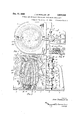
Figure 1 is a top plan View of a permanent mold embodying the principles of the invention, portions of the base plate being cut away;
Figure 2 is a central vertical sectional view of the structure shown in Figure 1, taken along the parting plane of the mold halves;
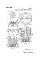
Figure 3'is a central vertical sectional view,
on the'parting plane, of the lower portion of the core box when in inverted position for forming the lower core portion; V Figure 4 is a top plan view of the part shown in Figure 3; V
Figure 5 is a central vertical sectional view of the structure shown in Figure 3 when inverted to its final position for the completion of the remaining portion of the core;
Figure 6 is a top plan View of the structure shown in Figure 5;
a Figure 7 is a view similar to Figure 5, with the upper portion of the core box in place;
Figure 8 is a top plan view of the structure shown in Figure 7;
Figure 9 is a fragmentary sectional view show ing a modified form of baked sand core for one head portion of the mold;
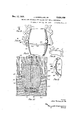
Figure 10 is a central vertical sectional view, taken along the plane of the sprues, showing the core illustrated in Figures 2 and '7 in assembled relation with the cope and drag sections of a green sand flask;
Figure 11 is a side elevation of the article produced in the mold shown in Figure 2, with the attached sprues, runners and risers;
Figure 12 is a fragmentary plan view, partly in section, taken along the line l2l2, shown in Figure 11, looking in the direction of the arrows;
Figures 13 and 14 are sectional views, taken along the lines I 3-! 3 and MM, respectively, shown in Figure 11, looking in the direction of the arrows; and
Figure 15 is a fragmentary view of a corner portion of a structure similar to that shown in Figure 11, with a modified type of metal feeding passageways.
As is clearly shown in Figures 1 and 2 of the 6 extending upwardly and then forwardly and provided with an aperture 1 in said forward portion to receive a bearing pin 8 upon which the separable mold sections, presently to be described, are pivotally engaged. The lower end of the bearing pin 8 is engaged in a socket 9 formed in the base plate approximately centrally of the meeting line of the wide and narrow base plate portions. The bearing pin is secured against movement in the supporting,
For forming a cast aluminum beer barrel, as shown in the drawings two movable mold sections are provided on each side of the central vertical parting plane of the mold, the lower sections I2 being of less vertical height than the upper sections l3. The left hand lower section l2, if viewed from the side of the mold opposite the bearing pin, is formed with apertured lugs l 4, I5, pivotally engaged upon the bearing pin 8, and its companion lower member E2 on the right hand side is formed with apertured lugs l6, l1, engaged upon said bearing pin and alternately spaced above the lugs M, [5 of the companion member so as to perengaged about the bearing pin 8,-the lower. lug2| resting uponthe upper surface of the lug I 8. Any suitable fastening means, such as conventional clamping yokes and wedges (not shown), may be used to secure the front edges of the mold in tightly clamped relation.
The movable mold sections, when held in closed position, will present a casting cavity 23 ofthe conventional shape of a beer barrel, the lower portion terminating at a point slightly above the upper surface ofthe base plate, the end and inner flange portions of said casting cavity being formed by a core print 24 and a sand core 25 in conjunction with the lower portion of the movable mold sections 12. The upper portion of the casting cavity is formed preferably by means of a baked sand core section 26 supported in a recess formed between the upper movable mold sections 13 and having upwardly and outwardly beveled sides 21 extending about the greater portion of the circumference of the mold halves. At the parting plane of the upper mold sections on each side, a riser cavity 28 is provided, said riser cavity being formed partially in the baked sand core and partially in the movable upper mold sections, and being wider adjacent its upper portion than adjacent its point of communication with the casting cavity. The meeting faces of the upper mold sections K3 are each provided with a. sprue cavity 29 preferably bent first in a direction toward the cavity and then away therefrom and then again toward the cavity and away therefrom to a point of discharge into a feeder cavity 3| supplying metal to a circumferential runner cavity 32 and to the casting cavity through a series of thin gates 33 at intervals about the entire circumference of the casting cavity. An upwardly directed feeder passageway 34 is provided to supply metal from the sprue 29 in an upward direction to the upper margin of the casting cavity adjacent the point of the merging of the riser cavity 28 with the cavity 35 for forming the upper flange or chime of the barrel. The casting cavity is defined between the movable mold members IZ and I3 and the core 36, the detailed construction of which will be presently described. Theupper end of the core terminates short of the baked sand core member 26 providing an upper section of the casting cavity 3'5 within which the upper head portion of the barrel is formed:
In the construction shown in Figures 1 and 2 as well as in Figure 10, the other head member of the barrel is not formed simultaneously with the body portion of the barrel and the integral head portion, but is preformed and is united with the bodyportion of the barrel-when the metal is poured into the mold. It is to be understood, however, that in place of supplying one preformed head, two preformed heads may be utilized and a core may be utilized if desired, and only the body portion of the barrel need be formed in the casting cavity in such case, the heads becoming united with the body portion upon the cooling of the casting and the sand core being shaken from the interior of the barrel, as will be hereinafter described.
In place of forming the baked sand core 26 with risers, as shown in Figure 2, the upper core portion of the mold maybe formed in the manner shown in Figure 9. An annular member 4| with beveled upper and lower portions meeting along the central circumferential line may be formed of some suitable material such as aluminum or iron or steel, within which a portion of the baked sand core 42 is embedded, the lower portion of the baked sand core 43 having an outwardly flared portion to form the upstanding flanged areaabout the integral head of the barrel. The casting cavity outwardly of said upstanding flange portion is formed with an annular channel 44 which is fed by the feeder passageway 45 extending upwardly On each side of the mold at the parting plane from thesprue. 46, which passageway and sprue are similar .to the sprue 29 and passageway 34 heretofore described. The annular member Al is suitably shaped to be received within a beveled recess in the upper movable mold sections and when so supported provides the transverse casting cavity 41 to form the integral head of the barrel. The annular channel 44 produces an outwardly projecting rib upon the completed casting which may be removed in any suitable manner, such as by chipping, or grinding, or the like. Such annular channel 44 serves to supply the upstanding flange portion of the barrel with sumcient metal to prevent shrinkage defects atthe top bead formed on the barrel flange, andto facilitate the casting operation.
In the permanent mold, the horizontal parting plane of the movable side members of the mold is below the center line of the mold in order to provide for the positioning of the bung hole on such center line free ofthe fins and other elements which would detract from the strength and appearance of the barrel at such point, if formed at the parting plane. The bung hole is formed by means of a baked sand plug 48 seated in a socket 49 formed by a core print 60 at a point where the core is flattened slightly to produce a flattened wall area 50 on one side of the barrel.
The permanent mold just described is adapted to form the outer surface of the barrel, as well as the projecting end portions or chimes thereof beyond the respective heads, and in the preferred form of construction to form the outer surface of one head member. The other head member in the preferred form of construction is preformed and is embodied in the core which will now be described.
The core is formed in the core box, as shown in Figure 7, having a lower section formed of two halves 5|, 52, and a single upper section 53. The core box may be formed of wood or metal, but as shown is formed of aluminum. The lower sections 5| are provided with lateral extensions 54 adjacent their upper portions providing vertical flanges for clamping the sections together and horizontal flanges providing a socket for an alining pin 55 for bringing the upper and lower sections into registry, as will be hereinafter explained. At the base of each of the lower halves 5|, 52, an extension base plate 55 is provided, said plate at the parting plane of the halves being provided with upward extension 57 for clamping said halves together.
The single upper section of the core box 53 is formed at its lower portion with an annular extension 58 adapted to rest upon the horizontal flange of the two-part lower section when assembled, said extension being provided with apertures at the parting plane to receive the alining pins 55 hereto-fore referred to. The upper edge portion 59 of the upper section 53 of the core box terminates slightly below the top of the core cavity and is formed with a cylindrical outer face 6 I, serving as a guide for the annular sweep support 62 adjustably supporting the inwardly directed sweeps 53- by means of bracket arms 65. The annular sweep support 62 is formed with a flat bearing face 65 at its under side which rests against rollers 66 rotatably' mounted upon horizontal pins 61 secured to the enlarged upper edge portion of the upper section 59; Four such rollers are shown and the annular sweep support accordingly is firmly supported upon the upper portion of the flask so as to shape the upper portion of the core uniformly as each core is completed.
The interior of the core box provides a cavity of the general configuration of a beer barrel throughout the main body portion thereof, but may be provided with annular enlargements 68, 69 at intermediate points of each half so as to formslight depressions around the core which will provide for beveled ribs on the interior of the finished casting at points intermediate of each half a section thereof.
In addition to the main body portion of' the core, the core box is adapted to receive the preformed head member which, it will be noted,
is formed with an extension marginal edge 1| adapted to project into the casting cavity, such edge preferably being formed with a depression on each side spaced slightly from the edge so as to leave the extreme edge portion in the form of a pear shaped bead. The lower core sections are formed with an enlargement 12 on the inner face having an annular notch 1-3 to receive the extensions of the preformed head member of the barrel. The lower portion of the core box is shaped to provide for a recess 14 to form the bead on the projecting flange portion or chime of the barrel and beneath such portion has an opening with beveled sides 15 to receive the print ring 16 formed as a flange upon a core frame 11 in the shape of a spoked wheel. An upstanding boss 18 is formed centrally of the frame, said boss being centrally apertured in alinement with an opening 19 in the precast head member. The opening 19 -is preferably a beveled opening formed as part of a filling fixture terminal 8| which is embodied centrally as a portion of the precast head. Such filling fixture terminal is of conventional form and forms no part of the present invention.
The upstanding boss 18 centrally of the core frame 11 is provided with an enlarged aperture 82 adjacent its outer portion and with a screw threaded section 83 of smaller diameter at its free end to receive the screw threaded end 84 of an arbor 85 which is inserted centrally of the core box, as will be hereinafter explained. The arbor intermediatethe screw-threaded portion and themain body portion is formed with a shank 86 extending through the central opening 19 of the filling terminal 8! in the precast head. The core frame. 11 is provided with a plurality of standards 81 at points spaced from the central upstanding boss 18 and of a height adapted to engage with their free ends the outer surface of the precast head which, as has been indicated, rests centrally against the. free end of the upstanding boss. The arbor is suitably tapered to provide for its easy Withdrawal from the core and its upper end is formed with a tapered portion against the lower area of which the inner ends of the sweeps B3 engage. A cross bar 88 is engaged through a transverse aperture 89 in the upper end of the arbor to provide a means for lifting the core and placing the same in either the permanent mold or the green sand mold, as may be required.
The core is formed in several stages, the first .step, as shown in Figures 3 and 4, requiring the jecting upper head plate 101engaged in the annular notch 13 and with the core frame 11 bearing against said plate immediately above the same. Green sand is then rammed into place through the spokes of r the frame support to form the lower portion SI of the core, the excess sand being struck off above head plate and in the upstanding boss 18 of the core frame support and screwed into firm engagement with the screw-threaded socket 83. The arbor is held in a central position by means of the guide bar 92 which is provided with a central notch 93 to engage the arbor and is held at its ends by the alining pins 55. The lower portion of the core box is then ready for the ramming of the lower section 94 of the core and when the core box is filled, the guide bar 92 is removed and the upper section of the core box is fitted into place on the lower core box sections, the alining pins 55 bringing the same into proper'alinement therewith. The assembled core box clamped in conventional manner is then ready for filling to the top which is accomplished by ramming the upper portion 95 of the core with green sand and thereupon placing the support for the sweeps about the upper edge and rotating the same to suitably form the top surface of the cor The core box is then removed from the core and the core is lifted bodily by means of the arbor and engaged in the recess in the base plate of the permanent mold, when it is desired to use that type of mold to form the casting, or, is engaged in a like recess formed in the'drag of a green sand mold to receive the print at the base of the core, as will presently be described.
With the mold assembled, as shown in Figure 2 of the drawings, with movable sides of the permanent mold tightly clamped to each other in conventional manner, the apparatus is ready for the casting operation which is carried on preferably by pouring the metal through each of the sprues 29. The metal will flow down the sinuous passageways of said sprues with some retardation of the rate of flow and will enter the circumferential runner about the structure and flow through the gates into the casting cavity and will at first flow downwardly about the margins of the precast head enveloping such marginal edges and to a certain extent fusing therewith and shrinking thereupon to form an integral structure. As the metal in the casting cavity rises, it will form the main body portion of the barrel and as it reaches the upper portion of the barrel will form the profiange thereof, such flange being adequately supplied by metal through the upwardly directed feeder passageways communicating with the respective sprues and from the risers communicating with the upper margins of the projecting flange adjacent the opposite sides of the parting plane of the mold. When the casting has sufficiently cooled, the mold is thrown open and the excess metal is broken from or otherwise removed from the surface of the casting. The casting, before such metal is removed, will exhibit the structural features shown in Figure 11, wherein the main body portion of the barrel Illl is surrounded at a point slightly below its center line by a circumferential runner I02 connected at intervals by narrow gate webs I03 with the outer surface of the casting. The sprue metal I04 will be in sinuous form and the risers I05 will be connected with the sprues by the feeder ....ure 10 is used, the drag portion [2! metal 106 formed by the upwardly directed passageways. After the excess metal is removed from the outer portion of the casting, the core frame and its adherent sand is removed and the baked sand core is removed from the end of the casting and the main body of the core is then removed through the lateral bung hole by shaking, washing, or by means of an air blast, as may be found most convenient.
The finished structure provides a barrel having light weight and fine grained texture on its inner and outer surfaces. If desired, the inner surface of the barrel may be coated with pitch or any of the usual lining materials utilized for containers for malt beverages and the like. It also has the advantage of holding the contents at the required temperature with a lesser amount of refrigerating agent, and lends itself readily to cleansing and pasteurizing operations. It further has the advantage of maintaining the quality of the contents notwithstanding wide variations in temperature above and below those found injurious to the contents of such liquids in other containers.
In place of providing risers at the upper margin of the casting cavity of the permanent mold, the casting cavity may be modified as has been explained in connection with the description of Figure 9, to form a casting of the type shown in Figure 15, wherein a circumferential runner III is formed about the outer margin of the upwardly projecting flange and supplies adequate metal to such part through the upwardly directed feeder passageways 45 communicating with the sprues H3. The remaining portion of the barrel H t will be substantially like that shown in Figure 11.
When, it is desired to produce a barrel in a green sand mold, the construction shown in Figof the mold being formed with a recess IE2 at the base of the casting cavity therein to receive the print of the core, which core is built up as has heretofore been described. The cope section of the mold I23 is filled when in inverted position in the usual manner and is provided with a recess l2 with beveled margins to receive the baked sand core I25 for forming the outer surface of the integral eead portion of the barrel, as well as the projecting flange portions of the barrel, such baked sand core being secured by means of suitable supports shown as wires [26 extending through the cope section of the mold and secured in conventional manner by means of cross wires I21 or the like to maintain such baked sand core in suitable position at the top of the casting cavity of the cope. The sprue passageways utilized in the sand mold are shown in the form of straight passageways I28 extending from the top of the cope downwardly to the parting plane of the cope and drag sections of the mold which are preferably located at the central horizontal plane of the casting cavity. The sprue passageways are downwardly tapered and the lower portion of the cope is formed with a circumferential runner passageway l29 communicating with a thin gate l3l which may be continuous about the casting cavity or similar to the gate shown in Figure 12, for the permanent mold wherein it is interrupted at intervals about the circumference of the casting cavity, the intervals lfilil between the gates being somewhat greater opposite the lower ends of the sprue passageways in order to divert the metal laterally preliminary to its entering the casting cavity.
The sand core when finished as shown in Figure '7, having the plug in position for forming the bung hole and shaped to provide a somewhat thickened area about the bung hole as heretofore described, after the removal of the core box is seated within the drag section iii of the green 5 sand mold. The arbor 85 of the core is then unscrewed and withdrawn and the central opening left in said core is filled with sand to the top of the main body portion of the core. The cope section 923 of the green sand mold is then placed 10 in position, the assembled structure then appearing as shown in Figure 10 of the drawings. The metal is poured preferably simultaneously down each of the sprues E28 and the margins of the precast head "it are partially fused and integrally 15 united with the metal introduced into the casting cavity. As the metal rises in the mold cavity it forms the structure substantially identical with the cavity shown in Figure 10 of the drawings.
After the metal has cooled sufficiently, the cope 20 section is removed and thereafter the cast barrel is disengaged from the drag section and the excess metal is broken away from the exterior of the casting and the core sections at the ends of the barrel are removed therefrom and the sand 25 core within the interior of the barrel is removed by shaking,washing, or by means of an air blast or other convenient methods, through the bung hole at the side of the barrel and the opening at the end thereof.
The article finished in the green sand mold will exhibit substantially all the characteristics of the article heretofore described as constructed in the permanent mold, but may have slightly less fine grain about the surface thereof, and does not lend itself to as rapid rate of production as in the metal. mold. The thin gate provided in the green sand mold serves to prevent more highly oxidized and less freely flowing metal from entering the casting cavity and thus insures a high 40 quality of metal within the casting cavity which will accurately conform to the shape of such cavity and form a casting free of irregularities and defects which might otherwise enter the article through the metal feeding passageways.
Other modes of applying the principle of my invention may be employed instead of those explained, change being made as regards the means and steps herein disclosed, provided the means stated by any of the following claims or the equivalent of such stated means be employed.
I therefore particularly point out and distinctly claim as my invention:
1. A method of casting a beer barrel of conventional outline from aluminum or aluminum alloys, which includes the steps of preforming one head member of the barrel in a separate casting operation with an extension marginal area about said head member of a size to project into the casting cavity for the main body portion of the barrel, forming a core for the barrel of green sand in a separable core box with a print for the bung hole, and with the preformed head member embedded in said core in spaced relation to the end of said core with the extension marginal area of said head projecting outwardly from said core a distance sufficient to bring the same at a point substantially centrally of the casting cavity, assembling the sections of the mold upon said core, pouring the metal for the body portion of the barrel together with the integral head section thereof, whereby the flange portions of the preformed head member will be surrounded by the molten metal of the body portion of the barrel and will unite and shrink into close union there- 16 with to form substantially an integral structure, and thereafter removing the interior portion of said sand core through the bung hole provided in the side of the barrel structure.
2. A method of casting substantially closed containers having side walls and integrally united heads, which includes the steps of preforming one head member with a marginal extension provid- A ing an enlarged circumferential bead, in a preliminary casting operation, providing sections of the' mold for the remaining structure, forming the core in a separable core box with the preformed head member embedded in said core and with its marginal extensions projecting therefrom, with the main body portion of the core above the same and a supporting print and core portion below the same, assembling the core with the mold members with the supporting print in the drag member of the mold and with the enlarged circumferential bead of the head member margins projecting into the casting cavity, providing an outer core for forming the integral head member, pouring the'metal into the casting cavity intermediate the core and assembled mold sections, whereby the metal in the casting cavity will engage about and shrink upon the marginal extensions of the head member, and thereafter removing said core from said completed casting.
3. A method of casting a beer barrel of conventional outline from aluminum or aluminum alloys, which includes the steps of preforming one head member of the barrel in a separate casting operation with an extension marginal area about said head member of a size to project it into the casting cavity for the main body portion of the barrel, forming a core for the barrel of green sand in a separable core box with a print for the bung hole, and with the preformed head member embedded in said core in spaced relation to the end of said core with the extension marginal area of said headprojecting outwardly from said core a distance sufiicient to bring the same at a point substantially centrally of the casting cavity, and with a core section and supporting print beneath said head member, providing an outer core for the integral head member, assembling the sections of the mold upon said cores, pouring the metal for the body portion of the 4 barrel together with the integral head section thereof, whereby the extension portions of the preformed head member will be surrounded by the molten metal of the body portion of the barrel and will unite and shrink into close union 5 therewith to form substantially an integral struc- 55f ture, and thereafter removing the interior por tion of said sand core through the bung hole provided in the side of the barrel structure.
'4. An apparatus for forming cast aluminum beer barrels which comprises a base plate, a recess in said base plate to receive a core supporting print, a plurality of movable metallic mold members supported onrsaid base plate and adapted to be moved into close relation above the same to provide a casting cavity, a sand core embodying a portion of said container wall with the margins thereof projecting into the casting cavity, extending upwardly from said core supporting print, a core plug for forming a bung hole supported in said core and an outer core supported in spaced relation to said first named core to form a portion of the outer surface of said barrel. a
5. An apparatus for forming cast aluminum beer barrels which comprises a base plate, a recess in said base plate to receive a core supporting print, a bearing pin rigidly secured to said base plate rearwardly of said recess, a plurality o1 horizontally movable mold sections pivotally mounted on said bearing pin and disposed in pairs on each side of said recess, the lowermost of each pair slidingly supported on said base plate, and a sand core supported'on a print engaged in said recess in the base plate and having embodied in its structure a precast head member for said barrel supported in slightly spaced relaber for said barrel supported'on said baked sand core member and a green sand core member supported on said precast head member, a plurality of separable metal mold members having a 25 vertical parting plane and a substantially centrally positioned horizontal parting plane adapted to be spaced about said core member to provide a casting cavity, and an upper core member supported in said mold members in spaced relation to said first-named core to complete the upper portion of said casting cavity;
'7. An apparatus for forming cast aluminum barrels, having in combination a base plate, a recess in said base plate to receive a core supporting print, a core having a core print at its bottom portion, a baked sandcore member associated with said core print, a precast head member for said barrel supported on said baked sand core member and a green sand core member Sup- 40 gate formed in one surface of said mold mem- 5o bers at the horizontal parting plane, a circumferential runner passageway outwardly of said gate and communicating therewith, and a sprue passageway in the vertical parting plane of said ,7
mold members extending from the upper portion of said mold to said runner passageway.
8. An apparatus for forming cast aluminum barrels, having in combination a base plate, a
recess in said base plate toreceive a core supporting print, a core having a core print at its bottom portion, a baked sand core member associated with said core print, a precast head member for said barrel supported on said baked sand core member and a green sand core 'member supported on said precast head member, a plurality of separable metal mold members having a vertical parting plane and a substantially centrally positioned horizontal parting plane adapted to be spaced about said core member to provide a casting cavity, an upper core member supported in said mold members in spaced relation to said first-named core to complete the upper portion of said casting cavity, a circumferential gate formed in one surface of said mold members at the horizontal parting plane, a cir- 76 cumferential runner passageway outwardly of said gate and communicating therewith, sprue passageways in the vertical parting plane of said mold members extending from the upper portion of said mold to said runner passageway, and riser passageways adjacent the upper portion of said mold members in the vertical parting plane communicating with the upper portion of the casting cavity.
9. An apparatus for forming cast aluminum barrels, having in combination a base plate, a recess in said base plate to receive a core supporting print, a core having a core print at its bottom portion, a baked sand core member associated with said core print, a precast head member for said barrel supported on said baked sand core member and a green sand core member supported on said precast head member, a plurality of separable metal mold members having a vertical parting plane and a substantially centrally positioned horizontal parting plane adapted to be spaced about said core member to provide a casting cavity, an upper core member supported in said mold members in spaced relation to said first-named core to complete the upper portion of said casting cavity, a circumferential gate formed in one surface of said mold members at the horizontal parting plane, a circumferential runner passageway outwardly of said gate and communicating therewith, sprue passageways in the vertical parting plane of said mold members extending from the upper portion of said mold to said runner passageway, and riser passageways adjacent the upper portion of said mold members in the vertical parting plane communicating with the upper portion of the casting cavity and having upwardly directed passageways connected with the adjacent sprue passageways.
10. An apparatus for forming cast aluminum barrels, having in combination a mold having separable members having an intermediate horizontal parting plane and having an associated core and supporting in one mold member in an intermediate position as a part of such core a precast head member for said barrel with marginal portions projecting outwardly therefrom, with a core print and baked sand core member beneath said head and a green sand core member above said head, said assembled core spaced from the inner walls of the separable mold members to provide a casting cavity; a thin circumferential gate at the horizontal parting plane of the separable mold members, an enlarged circumferential runner passageway connected with the outer margin of said gate, and sprue passageways connected with said runner.
JOHN SCHMELLER, SR.
Priority Applications (1)
| Application Number | Priority Date | Filing Date | Title |
|---|---|---|---|
| US694711A US2024950A (en) | 1933-08-19 | 1933-10-23 | Method and apparatus for making cast metal containers |
Applications Claiming Priority (2)
| Application Number | Priority Date | Filing Date | Title |
|---|---|---|---|
| US685955A US1932325A (en) | 1933-08-19 | 1933-08-19 | Cast metal container and method for making the same |
| US694711A US2024950A (en) | 1933-08-19 | 1933-10-23 | Method and apparatus for making cast metal containers |
Publications (1)
| Publication Number | Publication Date |
|---|---|
| US2024950A true US2024950A (en) | 1935-12-17 |
Family
ID=27103710
Family Applications (1)
| Application Number | Title | Priority Date | Filing Date |
|---|---|---|---|
| US694711A Expired - Lifetime US2024950A (en) | 1933-08-19 | 1933-10-23 | Method and apparatus for making cast metal containers |
Country Status (1)
| Country | Link |
|---|---|
| US (1) | US2024950A (en) |
-
1933
- 1933-10-23 US US694711A patent/US2024950A/en not_active Expired - Lifetime
Similar Documents
| Publication | Publication Date | Title |
|---|---|---|
| CN110586865B (en) | Universal casting method for small and medium-sized steel castings | |
| US2024950A (en) | Method and apparatus for making cast metal containers | |
| US1745891A (en) | Apparatus for casting metal articles | |
| CN106734926A (en) | A kind of cast structure of speedy drivage machine transmission case body | |
| US1932325A (en) | Cast metal container and method for making the same | |
| US4719958A (en) | Method, apparatus and feeder sleeves for the production of casting moulds | |
| GB1133029A (en) | Mold | |
| US4512385A (en) | Mold registration apparatus | |
| US1938707A (en) | Process or method of casting | |
| US3010167A (en) | Method of casting air brake hose couplings | |
| JPS58196159A (en) | Die for forging of molten metal | |
| US5476135A (en) | Mold box for forming sand pouring basins | |
| CN214920259U (en) | Aluminum alloy tilting casting die | |
| US2116630A (en) | Method of casting tubular members | |
| GB425209A (en) | Cast metal container and method for making the same | |
| US1872899A (en) | Method of forming tapered holes in metal castings | |
| US395061A (en) | Ingot-mold | |
| US2079749A (en) | Apparatus for making a casting | |
| US2029499A (en) | Metal mold | |
| US2392968A (en) | Mold | |
| US1643419A (en) | Set-up and core bar for casting ingot molds | |
| US2057074A (en) | Method and apparatus for making cast metal articles | |
| CN100421835C (en) | Method for founding pipe fitting | |
| US1003709A (en) | Car-wheel molding and casting flask. | |
| US211951A (en) | Improvement in molding tubular articles |