US2024907A - Display container - Google Patents
Display container Download PDFInfo
- Publication number
- US2024907A US2024907A US3090A US309035A US2024907A US 2024907 A US2024907 A US 2024907A US 3090 A US3090 A US 3090A US 309035 A US309035 A US 309035A US 2024907 A US2024907 A US 2024907A
- Authority
- US
- United States
- Prior art keywords
- container
- wall
- display
- carton
- blank
- Prior art date
- Legal status (The legal status is an assumption and is not a legal conclusion. Google has not performed a legal analysis and makes no representation as to the accuracy of the status listed.)
- Expired - Lifetime
Links
- 238000010276 construction Methods 0.000 description 3
- 230000000153 supplemental effect Effects 0.000 description 3
- 230000001154 acute effect Effects 0.000 description 2
- 238000007789 sealing Methods 0.000 description 2
- 241000507564 Aplanes Species 0.000 description 1
- 239000000853 adhesive Substances 0.000 description 1
- 230000001070 adhesive effect Effects 0.000 description 1
- 239000012769 display material Substances 0.000 description 1
- 238000003197 gene knockdown Methods 0.000 description 1
- 230000004048 modification Effects 0.000 description 1
- 238000012986 modification Methods 0.000 description 1
- 230000003014 reinforcing effect Effects 0.000 description 1
Images

Classifications
-
- B—PERFORMING OPERATIONS; TRANSPORTING
- B65—CONVEYING; PACKING; STORING; HANDLING THIN OR FILAMENTARY MATERIAL
- B65D—CONTAINERS FOR STORAGE OR TRANSPORT OF ARTICLES OR MATERIALS, e.g. BAGS, BARRELS, BOTTLES, BOXES, CANS, CARTONS, CRATES, DRUMS, JARS, TANKS, HOPPERS, FORWARDING CONTAINERS; ACCESSORIES, CLOSURES, OR FITTINGS THEREFOR; PACKAGING ELEMENTS; PACKAGES
- B65D5/00—Rigid or semi-rigid containers of polygonal cross-section, e.g. boxes, cartons or trays, formed by folding or erecting one or more blanks made of paper
- B65D5/42—Details of containers or of foldable or erectable container blanks
- B65D5/44—Integral, inserted or attached portions forming internal or external fittings
- B65D5/52—External stands or display elements for contents
- B65D5/5213—Internal elements supporting the contents and movable for displaying them, e.g. movable bottoms or trays
Definitions
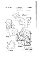
- Figure 1 is a plan view of one preferred type of blank, with solid lines indicating cut portions and dotted lines indicating fold lines.
- Fig. 2 is aplan view of the blank shown in Fig. 1, with the side walls secured together.
- Fig. 3 is a perspective view of the partially assembled set up container made from the blank shown in Fig. 2.
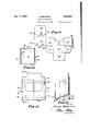
- Fig. 4 is a sectional view taken along the lines 4, 4 in Fig. 5.
- Fig. 5 is a perspective view of the first form of display container in fully packed condition.
- Fig. 6 is a sectional view taken in the same position as Fig. 4, showing the contents of the container.
- Fig. 7 is a perspective view of the container opened up and arranged in display position.
- Fig. 8 is a sectional view of the container in display position taken along the lines 8, 8 in Fig. '7.
- Fig. 9 is a plan view of another preferred type of display container, operative on the same principle as the'first form illustrated.
- Fig. 10 is a'sectional view of the set up box illustrated in the form of the blank in Fig. 9.
- Fig. 11 is a front elevation of the container shown in Figures 9 and 10, with packages in the container in display position. I
- Fig. 12 is a sectional view taken along the lines l2, l2 inFig.11.
- the blank I has a front wall I, side walls 2, and a back wall 3.
- the front, side and back walls are secured in tubular condition by a flap 4 having adhesive thereon, which extends from one of the side walls, and is secured against the inner surface of the 5 back wall 3, as indicated in Figures 2 and 3.
- the front wall I has a cut out portion 5 which is useful for exposing much more of the front row of articles within the container than could be exposed were the cut out portion omitted. 10
- the container is shipped flat in the condition illustrated in Fig. 2, and in order to set it up ready to receive its contents, the bottom wall 6, having side flaps I articulated thereto, and a back wall reinforcing flap, is folded up inside the 15 tubular enclosure formed by the front, back and side walls as illustrated in Fig. 3.
- the cover for the box is formed by a flap 9 which extends from the upper edge of the back wall 3.
- a locking tab II] is articulated to the flap 20 9, and lines of articulation II and a cut out portion I2 permit the cover to be folded along the lines of articulation ll so as to form a sort of easel on which display material may be supplied.
- the side walls 2 have an upwardly inclined lower edge l3, from which the rear lower corner I! of the container extends when it is in fully set up condition.
- Figs. 6 to 8 I have illustrated the contents of the container as consisting in six bottles IS.
- the cover when it is desired to arrange the container in display position, is elevated upwardly and then folded along the lines of articulation ll so that an easel-like display flap, best illus-- trated at IS in Fig '7, is formed.
- the flaps I and 8' telescope along the inner surfaces of the walls 2 and 3 until thebottom lies parallel with the diagonally extending lower edges of the side walls 2. This causes the bottles'to assume a spaced or staggered condition, in which their appearance is more individual and in which they attract more attention.
- Figs. 9 to 12 are substantially the same as those illustrated in Figs. 1 to 8, the only difference being that the bottom edge of the side flaps 2a form a continuous line with the bottom edges of the front and back flaps.
- the cover is formed by a flap 9a, having a sealing tongue Illa, a cut out panel l2a, and lines of articulation Ila.
- the back wall 3a is provided with cut out tabs Ila, which are folded outwardly from the surface of the wall 3a to provide locks to maintain the bottom wall 6a in position when the bottom wall is moved to display position.
- Figs. 9 to 12 The advantage of the construction illustrated in Figs. 9 to 12 is that articles such as are illus-. trated at l5a are moved to spaced or staggered position with the back row of articles elevated above the front row, and with intermediaterows proportionately elevated. While I have shown the locking tabs Ila for maintaining the bottom v forms no part of my invention, which consists primarily in the construction and arrangement which permits the bottom wall of the container to be moved to an elevated position, in which the articles in the container are staggered in spaced position.
- a two-purpose carton formed from a cut and scored blank, said carton for the purpose of shipment of goods therein being in the form of a right parallelepiped both interiorly and exteriorly, and said carton having a bottom hinged only to the front thereof, whereby for the purpose of display of the contents thereof the bottom may lar position.
- a carton formed from a cut and score-d blank having front, side and back walls adapted to be 25 secured in a carton enclosing band, with a bottom member having auxiliary side and back wall members hinged to the lower corner edge of the front wall, and means extending from one of the wall members for retaining said bottom member at an acute angle with respect to said front wall, wherebythe contents of the carton may be displayed in a staggered arrangement.
- a carton formed from a cut and scored blank having front, side and back walls adapted to be secured in a carton enclosing band, with a bottom member having auxiliary side and back wall members hinged to the lower corner edge of the front wall, and tabs extending from one of the back wall members for retaining said bottom 40 member at an acute angle with respect to said front wall when said carton is set up to display the contents of the carton in a staggered arrangement.
Landscapes
- Engineering & Computer Science (AREA)
- Mechanical Engineering (AREA)
- Cartons (AREA)
Description
.Dec. 17, 1935. s; BERGSTEIN 2,024,907
bIsPL'AY CONTAINER Filed Jan. 23, 1935 V s Sheets-Sheet 1 v INVENTOR. SAMUEL BERG-STEIN BY 46a.
' ATTORNEYS Dec. 17, 1935. s. BERGSTEIN DISPLAY CONTAINER Filed Jan. 25, 1935 5 Sheets-Sheet 2 INVENTOR. SAM/5L Bmvcsrnm ATTORNEYS.
Dec. 17, 1935. s. BERGSTEIN 2,024,907
DISPLAY CONTAINER Filed Jan. 23, 1955 '3 Sheets-Sheet 5 ATTORNEYS.
Patented Dec. 17, 1935 UNITED STATES PATENT OFFICE DISPLAY CONTAINER Samuel Bergstein, Middletown, Ohio Application January 23, 1935, Serial No. 3,090 4 Claims. 01. 206-44) In the ordinary type of display container when the cover is open the articles within the container do not show up to good advantage or have an interesting appearance because they are packed close together. The nearest row and the tops of other articles are substantially all that can be seen by a person looking at the opened container. It is an object of my invention to provide a container in which, by a simple manipulation, the articles within the container are moved to spaced positions, so that they present a more attractive appearance.
It is an object of my invention to make such a display container from, preferably a single cut and scored blank, which may be readily assembled from the knock down condition in which it is shipped.
Other advantages of the construction in the economy of board required and various other structural advantages will be apparent from the ensuing disclosure, in which I have illustrated two embodiments of my invention.
Referring to the drawings:-
Figure 1 is a plan view of one preferred type of blank, with solid lines indicating cut portions and dotted lines indicating fold lines.
Fig. 2 is aplan view of the blank shown in Fig. 1, with the side walls secured together.
Fig. 3 is a perspective view of the partially assembled set up container made from the blank shown in Fig. 2.
Fig. 4 is a sectional view taken along the lines 4, 4 in Fig. 5.
Fig. 5 is a perspective view of the first form of display container in fully packed condition.
Fig. 6 is a sectional view taken in the same position as Fig. 4, showing the contents of the container.
Fig. 7 is a perspective view of the container opened up and arranged in display position.
Fig. 8 is a sectional view of the container in display position taken along the lines 8, 8 in Fig. '7.
Fig. 9 is a plan view of another preferred type of display container, operative on the same principle as the'first form illustrated.
Fig. 10 is a'sectional view of the set up box illustrated in the form of the blank in Fig. 9.
Fig. 11 is a front elevation of the container shown in Figures 9 and 10, with packages in the container in display position. I
Fig. 12 is a sectional view taken along the lines l2, l2 inFig.11.
Referring first to the modification of my invention illustrated in Figs. 1 to a, the blank I has a front wall I, side walls 2, and a back wall 3. The front, side and back walls are secured in tubular condition by a flap 4 having adhesive thereon, which extends from one of the side walls, and is secured against the inner surface of the 5 back wall 3, as indicated in Figures 2 and 3.
The front wall I has a cut out portion 5 which is useful for exposing much more of the front row of articles within the container than could be exposed were the cut out portion omitted. 10
The container is shipped flat in the condition illustrated in Fig. 2, and in order to set it up ready to receive its contents, the bottom wall 6, having side flaps I articulated thereto, and a back wall reinforcing flap, is folded up inside the 15 tubular enclosure formed by the front, back and side walls as illustrated in Fig. 3.
The cover for the box is formed by a flap 9 which extends from the upper edge of the back wall 3. A locking tab II] is articulated to the flap 20 9, and lines of articulation II and a cut out portion I2 permit the cover to be folded along the lines of articulation ll so as to form a sort of easel on which display material may be supplied.
The side walls 2 have an upwardly inclined lower edge l3, from which the rear lower corner I! of the container extends when it is in fully set up condition. In Figs. 6 to 8 I have illustrated the contents of the container as consisting in six bottles IS.
The cover, when it is desired to arrange the container in display position, is elevated upwardly and then folded along the lines of articulation ll so that an easel-like display flap, best illus-- trated at IS in Fig '7, is formed. By pressing upwardly on the bottom wall 6, the flaps I and 8' telescope along the inner surfaces of the walls 2 and 3 until thebottom lies parallel with the diagonally extending lower edges of the side walls 2. This causes the bottles'to assume a spaced or staggered condition, in which their appearance is more individual and in which they attract more attention.
The'blank and container shown in Figs. 9 to 12 are substantially the same as those illustrated in Figs. 1 to 8, the only difference being that the bottom edge of the side flaps 2a form a continuous line with the bottom edges of the front and back flaps.
I have illustrated therefore a blank having a a front wall la. side walls 2a., a back wall 30., and a sealing tab 4a., the bottom being formed by an articulated flap 6a, having side flap extensions 1a,
and a back wall extension 8a. The cover is formed by a flap 9a, having a sealing tongue Illa, a cut out panel l2a, and lines of articulation Ila. The back wall 3a is provided with cut out tabs Ila, which are folded outwardly from the surface of the wall 3a to provide locks to maintain the bottom wall 6a in position when the bottom wall is moved to display position.
The advantage of the construction illustrated in Figs. 9 to 12 is that articles such as are illus-. trated at l5a are moved to spaced or staggered position with the back row of articles elevated above the front row, and with intermediaterows proportionately elevated. While I have shown the locking tabs Ila for maintaining the bottom v forms no part of my invention, which consists primarily in the construction and arrangement which permits the bottom wall of the container to be moved to an elevated position, in which the articles in the container are staggered in spaced position.
Having thus described my invention, what I claim as new and desire to secure by Letters Patent, is:-
1. A two-purpose carton formed from a cut and scored blank, said carton for the purpose of shipment of goods therein being in the form of a right parallelepiped both interiorly and exteriorly, and said carton having a bottom hinged only to the front thereof, whereby for the purpose of display of the contents thereof the bottom may lar position.
2. A carton formed from a cut and scored blank, having a front, two sides and a back, the front and back being in parallel planes and the sides and rear edges of said supplemental side walls converge toward the tops thereof, whereby for the shipment of goods therein the said carton is in the form of a right parallelepiped, with the bottom member in a horizontal position and the 15 rear edges of said supplemental side walls abutting the rear wall, and whereby for the purpose of display the said bottom member may be raised angularly with respect to the front, bringing the front edges of said supplemental side walls up 20 against the front wall, the rear wall of saidcarton being provided with means for maintaining the bottom member in its raised position.
3. A carton formed from a cut and score-d blank having front, side and back walls adapted to be 25 secured in a carton enclosing band, with a bottom member having auxiliary side and back wall members hinged to the lower corner edge of the front wall, and means extending from one of the wall members for retaining said bottom member at an acute angle with respect to said front wall, wherebythe contents of the carton may be displayed in a staggered arrangement.
4. A carton formed from a cut and scored blank having front, side and back walls adapted to be secured in a carton enclosing band, with a bottom member having auxiliary side and back wall members hinged to the lower corner edge of the front wall, and tabs extending from one of the back wall members for retaining said bottom 40 member at an acute angle with respect to said front wall when said carton is set up to display the contents of the carton in a staggered arrangement.
SAMUEL BERGSTEEN. v
Priority Applications (1)
| Application Number | Priority Date | Filing Date | Title |
|---|---|---|---|
| US3090A US2024907A (en) | 1935-01-23 | 1935-01-23 | Display container |
Applications Claiming Priority (1)
| Application Number | Priority Date | Filing Date | Title |
|---|---|---|---|
| US3090A US2024907A (en) | 1935-01-23 | 1935-01-23 | Display container |
Publications (1)
| Publication Number | Publication Date |
|---|---|
| US2024907A true US2024907A (en) | 1935-12-17 |
Family
ID=21704090
Family Applications (1)
| Application Number | Title | Priority Date | Filing Date |
|---|---|---|---|
| US3090A Expired - Lifetime US2024907A (en) | 1935-01-23 | 1935-01-23 | Display container |
Country Status (1)
| Country | Link |
|---|---|
| US (1) | US2024907A (en) |
Cited By (3)
| Publication number | Priority date | Publication date | Assignee | Title |
|---|---|---|---|---|
| US2688396A (en) * | 1951-07-16 | 1954-09-07 | Us Printing & Lithograph Compa | Single-blank display and shipping carton |
| EP2070824A1 (en) * | 2007-12-11 | 2009-06-17 | Saica Embalaje Centro, S.A. | Dispensing package comprising a ramp and method of assembly. |
| WO2011024802A1 (en) * | 2009-08-26 | 2011-03-03 | 株式会社ロッテ | Packaging container |
-
1935
- 1935-01-23 US US3090A patent/US2024907A/en not_active Expired - Lifetime
Cited By (5)
| Publication number | Priority date | Publication date | Assignee | Title |
|---|---|---|---|---|
| US2688396A (en) * | 1951-07-16 | 1954-09-07 | Us Printing & Lithograph Compa | Single-blank display and shipping carton |
| EP2070824A1 (en) * | 2007-12-11 | 2009-06-17 | Saica Embalaje Centro, S.A. | Dispensing package comprising a ramp and method of assembly. |
| WO2011024802A1 (en) * | 2009-08-26 | 2011-03-03 | 株式会社ロッテ | Packaging container |
| JP2011046398A (en) * | 2009-08-26 | 2011-03-10 | Lotte Co Ltd | Packaging container which is also used for display |
| CN102481997A (en) * | 2009-08-26 | 2012-05-30 | 罗蒂株式会社 | Packaging container |
Similar Documents
| Publication | Publication Date | Title |
|---|---|---|
| US3669251A (en) | Display cartons and convertible shipping and display cartons and blanks therefor | |
| US3680687A (en) | Display carton | |
| US2946433A (en) | Display cartons | |
| US2776083A (en) | Knockdown container | |
| US2741416A (en) | Container | |
| US2320665A (en) | Box | |
| US3019958A (en) | Hinge cover carton | |
| US3054505A (en) | Multi-article carton | |
| US1974552A (en) | Display carton | |
| US2006445A (en) | Display box | |
| US4117924A (en) | Display carton | |
| US1929490A (en) | Box | |
| US2269715A (en) | Display container | |
| US937173A (en) | Carton or box. | |
| US2124335A (en) | Shipping and display package | |
| US2112960A (en) | Dispensing receptacle and package | |
| US3111253A (en) | Combination package | |
| US1860309A (en) | Carton | |
| US2298136A (en) | Combination shipping and display carton | |
| US2773589A (en) | Display carton | |
| US2024907A (en) | Display container | |
| US3067925A (en) | Packages | |
| US2975953A (en) | Carton with cover lock | |
| US1497536A (en) | Box | |
| US3584740A (en) | Display carton |