US20190046292A1 - Palate anchorage device for orthodontics - Google Patents
Palate anchorage device for orthodontics Download PDFInfo
- Publication number
- US20190046292A1 US20190046292A1 US15/759,708 US201615759708A US2019046292A1 US 20190046292 A1 US20190046292 A1 US 20190046292A1 US 201615759708 A US201615759708 A US 201615759708A US 2019046292 A1 US2019046292 A1 US 2019046292A1
- Authority
- US
- United States
- Prior art keywords
- palatal
- anchor plate
- palate
- base member
- palatal anchor
- Prior art date
- Legal status (The legal status is an assumption and is not a legal conclusion. Google has not performed a legal analysis and makes no representation as to the accuracy of the status listed.)
- Granted
Links
- 210000003254 palate Anatomy 0.000 title claims description 28
- 238000011282 treatment Methods 0.000 claims description 10
- 210000004872 soft tissue Anatomy 0.000 claims description 6
- RTAQQCXQSZGOHL-UHFFFAOYSA-N Titanium Chemical compound [Ti] RTAQQCXQSZGOHL-UHFFFAOYSA-N 0.000 claims description 5
- 229910052719 titanium Inorganic materials 0.000 claims description 5
- 239000010936 titanium Substances 0.000 claims description 5
- 238000000034 method Methods 0.000 description 14
- 210000004400 mucous membrane Anatomy 0.000 description 10
- 206010061218 Inflammation Diseases 0.000 description 8
- 210000000988 bone and bone Anatomy 0.000 description 8
- 230000004054 inflammatory process Effects 0.000 description 8
- 210000004877 mucosa Anatomy 0.000 description 7
- 210000000214 mouth Anatomy 0.000 description 6
- 210000001519 tissue Anatomy 0.000 description 6
- 206010028851 Necrosis Diseases 0.000 description 5
- 230000001054 cortical effect Effects 0.000 description 5
- 230000017074 necrotic cell death Effects 0.000 description 5
- 238000007906 compression Methods 0.000 description 3
- 230000006835 compression Effects 0.000 description 3
- 238000012986 modification Methods 0.000 description 3
- 230000004048 modification Effects 0.000 description 3
- 230000007774 longterm Effects 0.000 description 2
- 239000000463 material Substances 0.000 description 2
- 206010063560 Excessive granulation tissue Diseases 0.000 description 1
- 206010033372 Pain and discomfort Diseases 0.000 description 1
- 229910000831 Steel Inorganic materials 0.000 description 1
- 238000004873 anchoring Methods 0.000 description 1
- 238000005452 bending Methods 0.000 description 1
- 210000004763 bicuspid Anatomy 0.000 description 1
- 238000010276 construction Methods 0.000 description 1
- 230000000694 effects Effects 0.000 description 1
- 238000005516 engineering process Methods 0.000 description 1
- 230000002708 enhancing effect Effects 0.000 description 1
- 210000001126 granulation tissue Anatomy 0.000 description 1
- 210000004283 incisor Anatomy 0.000 description 1
- 210000004379 membrane Anatomy 0.000 description 1
- 239000012528 membrane Substances 0.000 description 1
- 210000003928 nasal cavity Anatomy 0.000 description 1
- 238000004904 shortening Methods 0.000 description 1
- 239000010959 steel Substances 0.000 description 1
Images


Classifications
-
- A—HUMAN NECESSITIES
- A61—MEDICAL OR VETERINARY SCIENCE; HYGIENE
- A61C—DENTISTRY; APPARATUS OR METHODS FOR ORAL OR DENTAL HYGIENE
- A61C7/00—Orthodontics, i.e. obtaining or maintaining the desired position of teeth, e.g. by straightening, evening, regulating, separating, or by correcting malocclusions
- A61C7/12—Brackets; Arch wires; Combinations thereof; Accessories therefor
- A61C7/14—Brackets; Fixing brackets to teeth
- A61C7/145—Lingual brackets
-
- A—HUMAN NECESSITIES
- A61—MEDICAL OR VETERINARY SCIENCE; HYGIENE
- A61C—DENTISTRY; APPARATUS OR METHODS FOR ORAL OR DENTAL HYGIENE
- A61C7/00—Orthodontics, i.e. obtaining or maintaining the desired position of teeth, e.g. by straightening, evening, regulating, separating, or by correcting malocclusions
- A61C7/02—Tools for manipulating or working with an orthodontic appliance
-
- A—HUMAN NECESSITIES
- A61—MEDICAL OR VETERINARY SCIENCE; HYGIENE
- A61C—DENTISTRY; APPARATUS OR METHODS FOR ORAL OR DENTAL HYGIENE
- A61C7/00—Orthodontics, i.e. obtaining or maintaining the desired position of teeth, e.g. by straightening, evening, regulating, separating, or by correcting malocclusions
- A61C7/12—Brackets; Arch wires; Combinations thereof; Accessories therefor
- A61C7/14—Brackets; Fixing brackets to teeth
- A61C7/146—Positioning or placement of brackets; Tools therefor
-
- A—HUMAN NECESSITIES
- A61—MEDICAL OR VETERINARY SCIENCE; HYGIENE
- A61C—DENTISTRY; APPARATUS OR METHODS FOR ORAL OR DENTAL HYGIENE
- A61C7/00—Orthodontics, i.e. obtaining or maintaining the desired position of teeth, e.g. by straightening, evening, regulating, separating, or by correcting malocclusions
- A61C7/12—Brackets; Arch wires; Combinations thereof; Accessories therefor
- A61C7/20—Arch wires
- A61C7/22—Tension adjusting means
-
- A—HUMAN NECESSITIES
- A61—MEDICAL OR VETERINARY SCIENCE; HYGIENE
- A61C—DENTISTRY; APPARATUS OR METHODS FOR ORAL OR DENTAL HYGIENE
- A61C8/00—Means to be fixed to the jaw-bone for consolidating natural teeth or for fixing dental prostheses thereon; Dental implants; Implanting tools
- A61C8/0093—Features of implants not otherwise provided for
- A61C8/0096—Implants for use in orthodontic treatment
Definitions
- the present invention relates to a palatal anchor plate, which is fixedly installed to mid-palatal area (the roof of a mouth) and provides a rigid orthodontic anchorage for tooth movement, whereby the palatal anchor plate reduces a counteraction (movement of a tooth that is used as an anchorage), which occurs when a tooth is used as an orthodontic anchorage, and provides a rigid orthodontic anchorage for tooth movement in various directions, which is difficult to obtain when a tooth is used as an orthodontic anchorage.
- brackets are attached to the teeth and connected to each other by an orthodontic steel wire to apply continuous force to the teeth in the desired direction to cause movement of the teeth and to improve skeletal disharmony.
- counteraction occurs according to the law of force (counteraction meaning movement of a tooth or teeth that serve as an orthodontic anchorage for moving another tooth or teeth). Therefore, various methods for reducing the counteraction have been devised and used. However, there is still a demand for counter reaction methods that are easier and less invasive procedures to patients.
- an anchoring plate is installed to the palate (palate; roof of mouth that separates the oral cavity and the nasal cavity from each other), brackets or similar devices are attached to the teeth to be moved, and a spring or a rubber band (power chains or power threads) are connected between the anchor plate and the brackets to apply the tension to the teeth.
- a method of fixing the anchor plate in the oral cavity by implanting screws (screws) into the palatal bone is used.
- screws screws
- the present invention has been made to solve the above-mentioned problems, and relates to a palatal anchor plate that is fixedly installed to the mid-palatal area (the roof of a mouth) to secure rigid orthodontic anchorage for tooth movement and for modification of the skeletal structure.
- An objective of the present invention is to provide a palatal anchor plate being capable of minimizing inflammation of palatal tissues, thereby providing a stable and rigid orthodontic anchorage during a long-term orthodontic treatment period by allowing force to be applied in various directions required for movement of teeth and modification of the skeletal structure.
- the present invention provides a palatal anchor plate comprising: a base member ( 10 ) fixable to a palate by screws during orthodontic treatment of a tooth; and a hook portion ( 20 ) symmetrically extending leftward and rightward from the base member ( 10 ), wherein, the base member ( 10 ) has screw holes at a front portion and a rear portion thereof respectively, and around each of the screw holes ( 50 ), three cylindrical protrusions ( 30 ) are formed on a palatal side and arranged in a tripod shape, engagement recesses ( 40 ) and ( 40 ′) are positioned a predetermined distance from each other and formed at a posterior edge of each of a left portion and a right portion of the hook portion ( 20 ), thereby enabling engagement between the hook portion and a traction member, and the palatal anchor plate is made of pure titanium ASTM F67 Grade 3.
- the present invention it is possible to minimize inflammation of the soft tissue of the palate by minimizing a contact area. And it enables to keep distance between anchor plate and palatal mucosa by bi-tripod protrusions on the palatal side of the anchor plate and not to impinge the palatal mucosa.
- the material of the palatal anchor plate is pure titanium ASTM F67 Grade 3
- the palatal anchor plate has an advantage that it can be easily adjusted so as to conform to the contour of the palate of an individual patient.
- the hook portion is provided with a plurality of engagement recesses to be engaged with traction wires connected to traction members to fasten the traction members to an anchorage
- traction forces can be applied to the teeth in various directions. Since traction forces can be applied in various directions, the palatal anchor plate can be not only used for incisor retraction but also can be used as an anchor for molar retraction and intrusion, which can be difficult to obtain when teeth are used as anchors.
- FIG. 1 is a view illustrating a state in which a palatal anchorage according to a conventional art is installed in an oral cavity;
- FIG. 2 is a view illustrating the overall construction of the palatal anchor plate according to the present invention.
- FIG. 3 is a cross-sectional view illustrating a state in which a base member and a protrusion of the palatal anchor plate according to the present invention are fixed to the cortical bone of a palate;
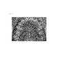
- FIG. 4 is a photograph showing a state in which the palatal anchor plate according to the present invention is installed to the palate.
- the palatal anchor plate for orthodontic treatment comprises a base member ( 10 ) fixable to a palate by screws during orthodontic treatment of a tooth; and a hook portion ( 20 ) symmetrically extending leftward and rightward from the base member ( 10 ), wherein, the base member ( 10 ) has screw holes at a front portion and a rear portion thereof respectively, and around each of the screw holes ( 50 ), three cylindrical protrusions ( 30 ) are formed on a palatal side and arranged in a tripod shape, engagement recesses ( 40 ) and ( 40 ′) are positioned a predetermined distance from each other and formed at a posterior edge of each of a left portion and a right portion of the hook portion ( 20 ), thereby enabling engagement between the hook portion and a traction member, and the palatal anchor plate is made of pure titanium ASTM F67 Grade 3.
- the palatal anchor plate is composed of the base member ( 10 ), the hook portion ( 20 ) including a left portion and a right portion which are in a pair, and the protrusion ( 30 ) composed of cylindrical protrusions among which three are arranged in a tripod shape at the front portion of the base member ( 10 ) and the other three are arranged in an inverted form at the rear portion of the base member ( 10 ).
- the base member ( 10 ) among the elements of the present invention is located at the center of the palatal anchor plate for orthodontic treatment. Screws (not denoted by reference symbol numbers) are driven into the palate through the respective holes ( 50 ) formed at the front portion and the rear portion of the base member ( 10 ), so that the palatal anchor plate for orthodontic treatment fixedly installed to the palate.
- a conventional palatal anchor plate is fixed to the palate of a patient by screws into the palate through multiple holes formed at a front portion and a rear portion of the palatal anchor plate.
- the palatal tissue around the palatal anchor plate and screws is compressed, which is likely to lead to necrosis of the palatal tissue and the increase of the granulation tissue due to the subsequent inflammation, thereby resulting in a high possibility of dislodgement of the screws and eventually resulting dislocation of the palatal anchor plate from the palate.
- the solution is the protrusion ( 30 ) composed of cylindrical protrusions arranged around the screw holes ( 50 ).
- the cylindrical protrusions three are symmetrically arranged in a tripod shape like “ ⁇ ” around one of the screw holes ( 50 ) and the other three are symmetrically arranged in an inverted form like “ ⁇ ” around the other screw hole ( 50 ).
- the protrusions are provided near the palate.
- the base member ( 10 ) does not press the palatal mucous membrane of a patient at all or just weakly comes into contact with the palatal mucous membrane when considering the average thickness of the soft tissue at the center of the palate.
- the palatal anchor plate enables ease of the procedure because there is no need for an incision of the palatal mucous membrane, thereby shortening the procedure time, improving patient convenience, and minimizing inflammation around the palatal anchor plate.
- the three cylindrical protrusions constituting the protrusion ( 30 ) are arranged around the screw holes ( 50 ) so that the base member ( 10 ) is not deformed by excessive force when the screw is driven into the palate, thereby preventing the base member ( 10 ) from pressing the palatal mucous membrane of patients.
- the cylindrical protrusions of the protrusion ( 30 ) have a diameter of 1 mm and are spaced at a pitch (L) of 4 mm to minimize the contact area between the protrusion ( 30 ) and the palatal mucous membrane.
- the height of the protrusion ( 30 ) is set to 1.0 to 1.2 mm by taking into consideration that the thickness of the soft tissue in the posterior part of the palate behind the palatal center (the position where the palatal anchor plate is actually fixed) is in a range of 1.0 to 1.2 mm on average. This setting is required because when the palatal anchor plate is fixed to a portion of the palate with the screws, the protrusion ( 30 ) first comes into contact with the cortical bone of the palate, thereby determining the position where the palatal anchor plate is fixed. Therefore, there is almost no compression of the tissue by the palatal anchor plate, thereby minimizing inflammation attributable to compression of the tissue and necrosis.
- the hook portions ( 20 ) include the left portion and the right portion symmetrically extending from the left and right sides of the base member ( 10 ).
- engagement recesses ( 40 ) and ( 40 ′) are formed in the posterior edge of the left portion and the right portion of the hook portion ( 20 ) at regular intervals.
- the engagement recesses ( 40 ) and ( 40 ′) are formed to enable engagement with a traction member such as an orthodontic rubber band or a spring.
- the engagement recesses ( 40 ) and ( 40 ′) are formed such that one or two engagement recesses ( 40 ′) are provided at a horizontal portion and two to four engagement recesses ( 40 ) are provided at an inclined portion of each of the left portion and the right portion of the hook portion ( 20 ).
- the hook portion ( 20 ) includes three to six engagement recesses ( 40 ) and ( 40 ′).
- the engagement recesses ( 40 ′) provided at the horizontal portion of the hook portion are designed to enable easy movement of anterior teeth
- the engagement recesses ( 40 ) provided at the inclined portion of the hook portions are designed to enable easy application of intrusive and/or retractive forces to molars and premolars.
- plates installed at left and right molars are connected to the engagement recesses ( 40 ) formed on the inclined portions of the posterior edge of the hook portion ( 20 ) via rubber band (power threads) so that traction forces are exerted on the left and right molars.
- predetermined screws for fixing the screw holes ( 50 ) of the palatal anchor plate fixed to the cortical bone ( 80 ) and the cancellous bone ( 90 ) of a patient through the pair of the screw holes ( 50 ) by the screws.
- the protrusion ( 30 ) is in contact with the palatal mucosa of a patient at three points, each contact point having a 1 mm diameter dot shape. Since the three protrusions are arranged in a tripod shape, the palatal anchor plate is stably positioned without being eccentrically loaded when they are fixed by the screws. Particularly, since the palatal mucosa of a patient is not pressed by the base member ( 10 ), there is no risk of necrosis of the underlying palatal mucosa.
- the hook portion ( 20 ) is integrally formed with the base member ( 10 ).
- the palatal anchor plate is easy to adjust to the contour of an individual patient.
- the material of the palatal anchor plate has proper strength and properties enabling easy bending.
- the palatal anchor plate is made of ASTM F67 pure titanium (Grade 3).
Landscapes
- Health & Medical Sciences (AREA)
- Oral & Maxillofacial Surgery (AREA)
- Dentistry (AREA)
- Epidemiology (AREA)
- Life Sciences & Earth Sciences (AREA)
- Animal Behavior & Ethology (AREA)
- General Health & Medical Sciences (AREA)
- Public Health (AREA)
- Veterinary Medicine (AREA)
- Orthopedic Medicine & Surgery (AREA)
- Dental Tools And Instruments Or Auxiliary Dental Instruments (AREA)
Abstract
Description
- The present invention relates to a palatal anchor plate, which is fixedly installed to mid-palatal area (the roof of a mouth) and provides a rigid orthodontic anchorage for tooth movement, whereby the palatal anchor plate reduces a counteraction (movement of a tooth that is used as an anchorage), which occurs when a tooth is used as an orthodontic anchorage, and provides a rigid orthodontic anchorage for tooth movement in various directions, which is difficult to obtain when a tooth is used as an orthodontic anchorage.
- In order to treat improper positioning of teeth and skeletal disharmony of the face, typically brackets are attached to the teeth and connected to each other by an orthodontic steel wire to apply continuous force to the teeth in the desired direction to cause movement of the teeth and to improve skeletal disharmony. However, when attempts are made to move the teeth, counteraction occurs according to the law of force (counteraction meaning movement of a tooth or teeth that serve as an orthodontic anchorage for moving another tooth or teeth). Therefore, various methods for reducing the counteraction have been devised and used. However, there is still a demand for counter reaction methods that are easier and less invasive procedures to patients.
- As such an attempt, an anchoring plate is installed to the palate (palate; roof of mouth that separates the oral cavity and the nasal cavity from each other), brackets or similar devices are attached to the teeth to be moved, and a spring or a rubber band (power chains or power threads) are connected between the anchor plate and the brackets to apply the tension to the teeth. In this case, in order to install the anchor plate to the palate, a method of fixing the anchor plate in the oral cavity by implanting screws (screws) into the palatal bone is used. However, due to the presence of the soft tissue and no proper stops not to impinge the soft tissues between a palatal anchor plate and the palatal bone, necrosis of the mucous membranes of the palate and inflammation around the screw and anchor plate occurs frequently. Such inflammation not only causes pain and discomfort to the patient, but also leads to dislodgement of screws, which is highly likely to result in dislocation of the palatal anchor plate.
- As a method for solving this problem, there is a method of exposing the cortical bone through a flap operation, then fixing an anchor plate to a palate with screws, and finally suturing the incision with a medical suture. However, this method is difficult to perform due to the complexity of the procedure and the rigid structure of palatal mucosa. Furthermore, since this procedure is an invasive procedure requiring incision of the mucous membrane, it is considered a treatment that increases the burden to the patient.
- In the Korea Utility Model No. 20-0464089 (Dec. 4, 2012), although the convenience of the procedure has been improved by directly fixing a palatal anchor plate to the mucous membrane with screws without incision the mucosa membrane, it is difficult to avoid necrosis and inflammation attributable to compression of the tissue by an anchor plate at a contact portion of the palatal mucous membrane.
- Therefore, to solve the above problems, there is a urgent need to develop new technology that goes beyond typical orthodontic treatments that uses a tooth as an orthodontic anchorage, by changing the design of a palatal anchor plate, whereby enabling ease of the procedure and enhancing convenience for patients.
- The present invention has been made to solve the above-mentioned problems, and relates to a palatal anchor plate that is fixedly installed to the mid-palatal area (the roof of a mouth) to secure rigid orthodontic anchorage for tooth movement and for modification of the skeletal structure. An objective of the present invention is to provide a palatal anchor plate being capable of minimizing inflammation of palatal tissues, thereby providing a stable and rigid orthodontic anchorage during a long-term orthodontic treatment period by allowing force to be applied in various directions required for movement of teeth and modification of the skeletal structure.
- In order to achieve the above objective, the present invention provides a palatal anchor plate comprising: a base member (10) fixable to a palate by screws during orthodontic treatment of a tooth; and a hook portion (20) symmetrically extending leftward and rightward from the base member (10), wherein, the base member (10) has screw holes at a front portion and a rear portion thereof respectively, and around each of the screw holes (50), three cylindrical protrusions (30) are formed on a palatal side and arranged in a tripod shape, engagement recesses (40) and (40′) are positioned a predetermined distance from each other and formed at a posterior edge of each of a left portion and a right portion of the hook portion (20), thereby enabling engagement between the hook portion and a traction member, and the palatal anchor plate is made of pure titanium ASTM F67 Grade 3.
- Means for solving the other specific problems according to the present invention is described in the following detailed description section of the present disclosure.
- According to the present invention, it is possible to minimize inflammation of the soft tissue of the palate by minimizing a contact area. And it enables to keep distance between anchor plate and palatal mucosa by bi-tripod protrusions on the palatal side of the anchor plate and not to impinge the palatal mucosa. In addition, since the material of the palatal anchor plate is pure titanium ASTM F67 Grade 3, the palatal anchor plate has an advantage that it can be easily adjusted so as to conform to the contour of the palate of an individual patient.
- Furthermore, since the hook portion is provided with a plurality of engagement recesses to be engaged with traction wires connected to traction members to fasten the traction members to an anchorage, traction forces can be applied to the teeth in various directions. Since traction forces can be applied in various directions, the palatal anchor plate can be not only used for incisor retraction but also can be used as an anchor for molar retraction and intrusion, which can be difficult to obtain when teeth are used as anchors.
-
FIG. 1 is a view illustrating a state in which a palatal anchorage according to a conventional art is installed in an oral cavity; -
FIG. 2 is a view illustrating the overall construction of the palatal anchor plate according to the present invention; -
FIG. 3 is a cross-sectional view illustrating a state in which a base member and a protrusion of the palatal anchor plate according to the present invention are fixed to the cortical bone of a palate; and -
FIG. 4 is a photograph showing a state in which the palatal anchor plate according to the present invention is installed to the palate. - Hereinafter, embodiments of the present invention will be described in detail with reference to the accompanying drawings. The embodiments of the present invention are provided to convey through and complete description of the present invention to those ordinarily skilled in the art. Therefore, the shapes of elements in the drawings are simplified for clarity.
- First, the palatal anchor plate for orthodontic treatment according to the present invention comprises a base member (10) fixable to a palate by screws during orthodontic treatment of a tooth; and a hook portion (20) symmetrically extending leftward and rightward from the base member (10), wherein, the base member (10) has screw holes at a front portion and a rear portion thereof respectively, and around each of the screw holes (50), three cylindrical protrusions (30) are formed on a palatal side and arranged in a tripod shape, engagement recesses (40) and (40′) are positioned a predetermined distance from each other and formed at a posterior edge of each of a left portion and a right portion of the hook portion (20), thereby enabling engagement between the hook portion and a traction member, and the palatal anchor plate is made of pure titanium ASTM F67 Grade 3.
- As illustrated in
FIG. 2 , the palatal anchor plate is composed of the base member (10), the hook portion (20) including a left portion and a right portion which are in a pair, and the protrusion (30) composed of cylindrical protrusions among which three are arranged in a tripod shape at the front portion of the base member (10) and the other three are arranged in an inverted form at the rear portion of the base member (10). - As illustrated in
FIGS. 2 and 3 , the base member (10) among the elements of the present invention is located at the center of the palatal anchor plate for orthodontic treatment. Screws (not denoted by reference symbol numbers) are driven into the palate through the respective holes (50) formed at the front portion and the rear portion of the base member (10), so that the palatal anchor plate for orthodontic treatment fixedly installed to the palate. - Meanwhile, according to a conventional art, as illustrated in
FIG. 1 , a conventional palatal anchor plate is fixed to the palate of a patient by screws into the palate through multiple holes formed at a front portion and a rear portion of the palatal anchor plate. In this case, the palatal tissue around the palatal anchor plate and screws is compressed, which is likely to lead to necrosis of the palatal tissue and the increase of the granulation tissue due to the subsequent inflammation, thereby resulting in a high possibility of dislodgement of the screws and eventually resulting dislocation of the palatal anchor plate from the palate. - The inventors of the present disclosure have conceived and completed the present invention as a result of long-term intensive research into a solution to the problems described above. The inventors of the present disclosure have found that, as shown in
FIG. 2 , the solution is the protrusion (30) composed of cylindrical protrusions arranged around the screw holes (50). Among the cylindrical protrusions, three are symmetrically arranged in a tripod shape like “∴” around one of the screw holes (50) and the other three are symmetrically arranged in an inverted form like “∵” around the other screw hole (50). The protrusions are provided near the palate. - That is, when the screw is driven into the palate through one of the screw holes (50) formed at the front portion and the rear portion of the base member (10) to fix the palatal anchor plate to the palate, distal ends of the three cylindrical protrusions of the protrusion (30) first come into contact with the cortical bone in the palate, thereby preventing the base member (10) from compressing the palatal mucous membrane of a patient. Therefore, due to the cylindrical protrusions, the base member (10) does not press the palatal mucous membrane of a patient at all or just weakly comes into contact with the palatal mucous membrane when considering the average thickness of the soft tissue at the center of the palate. The palatal anchor plate enables ease of the procedure because there is no need for an incision of the palatal mucous membrane, thereby shortening the procedure time, improving patient convenience, and minimizing inflammation around the palatal anchor plate.
- According to the embodiment, the three cylindrical protrusions constituting the protrusion (30) are arranged around the screw holes (50) so that the base member (10) is not deformed by excessive force when the screw is driven into the palate, thereby preventing the base member (10) from pressing the palatal mucous membrane of patients. The cylindrical protrusions of the protrusion (30) have a diameter of 1 mm and are spaced at a pitch (L) of 4 mm to minimize the contact area between the protrusion (30) and the palatal mucous membrane.
- The height of the protrusion (30) is set to 1.0 to 1.2 mm by taking into consideration that the thickness of the soft tissue in the posterior part of the palate behind the palatal center (the position where the palatal anchor plate is actually fixed) is in a range of 1.0 to 1.2 mm on average. This setting is required because when the palatal anchor plate is fixed to a portion of the palate with the screws, the protrusion (30) first comes into contact with the cortical bone of the palate, thereby determining the position where the palatal anchor plate is fixed. Therefore, there is almost no compression of the tissue by the palatal anchor plate, thereby minimizing inflammation attributable to compression of the tissue and necrosis.
- In addition, the hook portions (20) include the left portion and the right portion symmetrically extending from the left and right sides of the base member (10). In addition, engagement recesses (40) and (40′) are formed in the posterior edge of the left portion and the right portion of the hook portion (20) at regular intervals. The engagement recesses (40) and (40′) are formed to enable engagement with a traction member such as an orthodontic rubber band or a spring. The engagement recesses (40) and (40′) are formed such that one or two engagement recesses (40′) are provided at a horizontal portion and two to four engagement recesses (40) are provided at an inclined portion of each of the left portion and the right portion of the hook portion (20). That is, the hook portion (20) includes three to six engagement recesses (40) and (40′). The engagement recesses (40′) provided at the horizontal portion of the hook portion are designed to enable easy movement of anterior teeth, and the engagement recesses (40) provided at the inclined portion of the hook portions are designed to enable easy application of intrusive and/or retractive forces to molars and premolars.
- For example, as illustrated in
FIG. 4 , plates installed at left and right molars are connected to the engagement recesses (40) formed on the inclined portions of the posterior edge of the hook portion (20) via rubber band (power threads) so that traction forces are exerted on the left and right molars. - As illustrated in
FIG. 3 , predetermined screws (not denoted by reference symbol numbers)for fixing the screw holes (50) of the palatal anchor plate fixed to the cortical bone (80) and the cancellous bone (90) of a patient through the pair of the screw holes (50) by the screws. Here, the protrusion (30) is in contact with the palatal mucosa of a patient at three points, each contact point having a 1mm diameter dot shape. Since the three protrusions are arranged in a tripod shape, the palatal anchor plate is stably positioned without being eccentrically loaded when they are fixed by the screws. Particularly, since the palatal mucosa of a patient is not pressed by the base member (10), there is no risk of necrosis of the underlying palatal mucosa. - Further, it is preferable that the hook portion (20) is integrally formed with the base member (10). With such structure, the palatal anchor plate is easy to adjust to the contour of an individual patient.
- Therefore, ideally, the material of the palatal anchor plate has proper strength and properties enabling easy bending. According to the example, the palatal anchor plate is made of ASTM F67 pure titanium (Grade 3).
- Although the present invention has been described in conjunction with exemplary embodiments illustrated in the accompanying drawings, the embodiments are disclosed only for illustrative purposes and should not be construed as limiting the present invention. On the contrary, those skilled in the art would appreciate that various modifications and equivalent embodiments are possible without departing from the spirit of the present invention. It is therefore to be understood that the true scope of protection of the present invention is defined by the following claims.
Claims (5)
Applications Claiming Priority (3)
| Application Number | Priority Date | Filing Date | Title |
|---|---|---|---|
| KR10-2015-0133470 | 2015-09-22 | ||
| KR1020150133470A KR101573186B1 (en) | 2015-09-22 | 2015-09-22 | Palatal plate as a skeletal anchorage for orthodontic treatment |
| PCT/KR2016/008729 WO2017052069A1 (en) | 2015-09-22 | 2016-08-09 | Palate anchorage device for orthodontics |
Publications (2)
| Publication Number | Publication Date |
|---|---|
| US20190046292A1 true US20190046292A1 (en) | 2019-02-14 |
| US10485634B2 US10485634B2 (en) | 2019-11-26 |
Family
ID=54882806
Family Applications (1)
| Application Number | Title | Priority Date | Filing Date |
|---|---|---|---|
| US15/759,708 Active US10485634B2 (en) | 2015-09-22 | 2016-08-09 | Palate anchorage device for orthodontics |
Country Status (4)
| Country | Link |
|---|---|
| US (1) | US10485634B2 (en) |
| JP (1) | JP6585302B2 (en) |
| KR (1) | KR101573186B1 (en) |
| WO (1) | WO2017052069A1 (en) |
Cited By (4)
| Publication number | Priority date | Publication date | Assignee | Title |
|---|---|---|---|---|
| CN109567963A (en) * | 2019-01-24 | 2019-04-05 | 北京诺贝亚太教育科技有限公司 | Orthodontic bracket |
| CN113057750A (en) * | 2021-04-30 | 2021-07-02 | 南京市口腔医院 | Force application device and method based on invisible correction of tooth extraction case |
| US20220202536A1 (en) * | 2020-06-19 | 2022-06-30 | Yasuhiro Itsuki | Orthodontic appliance and pliers for orthodontics |
| USD1049385S1 (en) * | 2023-06-28 | 2024-10-29 | Hung Kuo Chou | Orthodontic appliance |
Families Citing this family (8)
| Publication number | Priority date | Publication date | Assignee | Title |
|---|---|---|---|---|
| KR101573186B1 (en) * | 2015-09-22 | 2015-12-01 | 한병주 | Palatal plate as a skeletal anchorage for orthodontic treatment |
| KR101897702B1 (en) | 2016-11-24 | 2018-09-12 | (주)바이오머테리얼즈코리아 | Palatal anchorage for orthodontic treatment |
| ES1238884Y (en) * | 2019-10-25 | 2020-03-12 | Such Palacios Jose Miguel | Orthodontic skeletal anchor device |
| KR102263929B1 (en) | 2020-11-27 | 2021-06-10 | 가톨릭대학교 산학협력단 | Minimize side-effect to the gingiva for orthodontic anchrage applaince |
| KR102733727B1 (en) * | 2022-03-29 | 2024-11-25 | 가톨릭대학교 산학협력단 | Jig for implantation used for fixing support member for orthodontics |
| WO2023204772A1 (en) * | 2022-04-19 | 2023-10-26 | Raghis Tuqa Rashad | Mini-screws anchored casted palatal plate for upper arch distalization |
| KR102848057B1 (en) | 2023-02-14 | 2025-08-20 | (주)쓰리디케이피 | Orthodontic instrument for correction of irregularities |
| KR102678632B1 (en) * | 2023-07-12 | 2024-06-26 | 주홍국 | palatal anchorage device for orthodontic treatment with enhanced support and method manufacturing palatal anchorage device |
Citations (6)
| Publication number | Priority date | Publication date | Assignee | Title |
|---|---|---|---|---|
| US6048204A (en) * | 1998-02-03 | 2000-04-11 | Lifecore Biomedical, Inc. | Self tapping screw type dental implant |
| US20130122446A1 (en) * | 2010-07-20 | 2013-05-16 | Cheol-gyu Lee | Orthodontic fixing apparatus |
| US20130189640A1 (en) * | 2010-10-05 | 2013-07-25 | Yoon Ah Kook | Orthodontic Supporting Member |
| US20150313659A1 (en) * | 2012-12-07 | 2015-11-05 | Kagoshima University | Fastening force auxiliary device for screw and screw with fastening force auxiliary device |
| US20160016474A1 (en) * | 2014-07-18 | 2016-01-21 | Sony Corporation | System and method for providing a controlled power supply |
| WO2016016474A1 (en) * | 2014-08-01 | 2016-02-04 | Ldr Medical | Bone implants |
Family Cites Families (9)
| Publication number | Priority date | Publication date | Assignee | Title |
|---|---|---|---|---|
| US4988351A (en) * | 1989-01-06 | 1991-01-29 | Concept, Inc. | Washer for use with cancellous screw for attaching soft tissue to bone |
| US20070259306A1 (en) * | 2006-05-05 | 2007-11-08 | Osteomed L.P. | Orthodontic Plate and Method |
| JP2008017930A (en) | 2006-07-11 | 2008-01-31 | Univ Nihon | Orthodontic abutment |
| KR100918966B1 (en) * | 2007-11-08 | 2009-09-25 | 박현상 | Orthodontic Device |
| KR200458725Y1 (en) | 2010-08-19 | 2012-03-07 | 주식회사 제일메디칼코퍼레이션 | Fixture of orthodontic device |
| KR200464089Y1 (en) * | 2011-06-23 | 2012-12-10 | 경희대학교 산학협력단 | Palatal Anchorage for Orthodontic Treatment |
| KR101539755B1 (en) * | 2013-05-29 | 2015-08-07 | 조선대학교산학협력단 | Fixing apparatus for orthodontic reatment |
| KR200474677Y1 (en) | 2014-06-16 | 2014-10-13 | 가톨릭대학교 산학협력단 | Minimize side-effect to the hard palate for orthodontic anchrage applaince |
| KR101573186B1 (en) * | 2015-09-22 | 2015-12-01 | 한병주 | Palatal plate as a skeletal anchorage for orthodontic treatment |
-
2015
- 2015-09-22 KR KR1020150133470A patent/KR101573186B1/en not_active Expired - Fee Related
-
2016
- 2016-08-09 WO PCT/KR2016/008729 patent/WO2017052069A1/en not_active Ceased
- 2016-08-09 US US15/759,708 patent/US10485634B2/en active Active
- 2016-08-09 JP JP2018532020A patent/JP6585302B2/en active Active
Patent Citations (6)
| Publication number | Priority date | Publication date | Assignee | Title |
|---|---|---|---|---|
| US6048204A (en) * | 1998-02-03 | 2000-04-11 | Lifecore Biomedical, Inc. | Self tapping screw type dental implant |
| US20130122446A1 (en) * | 2010-07-20 | 2013-05-16 | Cheol-gyu Lee | Orthodontic fixing apparatus |
| US20130189640A1 (en) * | 2010-10-05 | 2013-07-25 | Yoon Ah Kook | Orthodontic Supporting Member |
| US20150313659A1 (en) * | 2012-12-07 | 2015-11-05 | Kagoshima University | Fastening force auxiliary device for screw and screw with fastening force auxiliary device |
| US20160016474A1 (en) * | 2014-07-18 | 2016-01-21 | Sony Corporation | System and method for providing a controlled power supply |
| WO2016016474A1 (en) * | 2014-08-01 | 2016-02-04 | Ldr Medical | Bone implants |
Cited By (5)
| Publication number | Priority date | Publication date | Assignee | Title |
|---|---|---|---|---|
| CN109567963A (en) * | 2019-01-24 | 2019-04-05 | 北京诺贝亚太教育科技有限公司 | Orthodontic bracket |
| US20220202536A1 (en) * | 2020-06-19 | 2022-06-30 | Yasuhiro Itsuki | Orthodontic appliance and pliers for orthodontics |
| US11452580B2 (en) * | 2020-06-19 | 2022-09-27 | Yasuhiro Itsuki | Orthodontic appliance and pliers for orthodontics |
| CN113057750A (en) * | 2021-04-30 | 2021-07-02 | 南京市口腔医院 | Force application device and method based on invisible correction of tooth extraction case |
| USD1049385S1 (en) * | 2023-06-28 | 2024-10-29 | Hung Kuo Chou | Orthodontic appliance |
Also Published As
| Publication number | Publication date |
|---|---|
| JP2018526181A (en) | 2018-09-13 |
| JP6585302B2 (en) | 2019-10-02 |
| WO2017052069A1 (en) | 2017-03-30 |
| KR101573186B1 (en) | 2015-12-01 |
| US10485634B2 (en) | 2019-11-26 |
Similar Documents
| Publication | Publication Date | Title |
|---|---|---|
| US10485634B2 (en) | Palate anchorage device for orthodontics | |
| US20250213275A1 (en) | Intermaxillary Fixation Device And Method Of Using Same | |
| US8662889B2 (en) | Arch bars for use in maxillofacial surgery and orthodontics | |
| US7887324B2 (en) | Osteogenetic-orthodontic device, system, and method | |
| US10575926B2 (en) | Maxillary expander | |
| KR102800060B1 (en) | Maxillary expander and protractor | |
| US11857230B2 (en) | Maxillary expander and protraction device | |
| US20140186788A1 (en) | System and method for maxillary protraction in class iii malocclusion patients | |
| KR101137926B1 (en) | Buccal supporting device for orthodontics | |
| CN107518954B (en) | Distraction osteogenesis device | |
| KR20110121347A (en) | Orthodontic palate fixture | |
| US11730570B2 (en) | Bracket | |
| US20040197726A1 (en) | Clip type orthodontic anchor | |
| US8485817B2 (en) | Orthodontic device | |
| KR200411875Y1 (en) | Orthodontic Micro Implant Support Device | |
| RU2617181C1 (en) | Method for vertical bite pathology treatment | |
| Papadopoulos | The “Advanced Molar Distalization Appliance”: a novel approach to correct Class II malocclusion | |
| PARATE et al. | Anchorage | |
| CN201595953U (en) | Orthodontic micro-implanter stent | |
| KR20170072672A (en) | Anchorge for Orthodontic Treatment and method for manufacturing the same | |
| Tarraf | The application of skeletal anchorage in the correction of anterior open bite and skeletal Class III malocclusion: a paradigm shift | |
| ElAbbasy | Effects of orthopedic skeletal Class III correction in growing subjects using skeletal anchorage and Class III elastics | |
| CN117731426A (en) | Detachable device for preventing tooth grinding and correcting teeth and application method thereof | |
| CN117137653A (en) | Inverse correction method and its appliance | |
| KR20200058940A (en) | screw for orthodontic treatment |
Legal Events
| Date | Code | Title | Description |
|---|---|---|---|
| FEPP | Fee payment procedure |
Free format text: ENTITY STATUS SET TO UNDISCOUNTED (ORIGINAL EVENT CODE: BIG.); ENTITY STATUS OF PATENT OWNER: SMALL ENTITY |
|
| FEPP | Fee payment procedure |
Free format text: ENTITY STATUS SET TO SMALL (ORIGINAL EVENT CODE: SMAL); ENTITY STATUS OF PATENT OWNER: SMALL ENTITY |
|
| STPP | Information on status: patent application and granting procedure in general |
Free format text: NON FINAL ACTION MAILED |
|
| STPP | Information on status: patent application and granting procedure in general |
Free format text: RESPONSE TO NON-FINAL OFFICE ACTION ENTERED AND FORWARDED TO EXAMINER |
|
| STPP | Information on status: patent application and granting procedure in general |
Free format text: FINAL REJECTION MAILED |
|
| STPP | Information on status: patent application and granting procedure in general |
Free format text: DOCKETED NEW CASE - READY FOR EXAMINATION |
|
| STPP | Information on status: patent application and granting procedure in general |
Free format text: NOTICE OF ALLOWANCE MAILED -- APPLICATION RECEIVED IN OFFICE OF PUBLICATIONS |
|
| STPP | Information on status: patent application and granting procedure in general |
Free format text: PUBLICATIONS -- ISSUE FEE PAYMENT VERIFIED |
|
| STCF | Information on status: patent grant |
Free format text: PATENTED CASE |
|
| MAFP | Maintenance fee payment |
Free format text: PAYMENT OF MAINTENANCE FEE, 4TH YR, SMALL ENTITY (ORIGINAL EVENT CODE: M2551); ENTITY STATUS OF PATENT OWNER: SMALL ENTITY Year of fee payment: 4 |