US20180098461A1 - Heat conductive sheet and electronic apparatus using same - Google Patents
Heat conductive sheet and electronic apparatus using same Download PDFInfo
- Publication number
- US20180098461A1 US20180098461A1 US15/563,649 US201615563649A US2018098461A1 US 20180098461 A1 US20180098461 A1 US 20180098461A1 US 201615563649 A US201615563649 A US 201615563649A US 2018098461 A1 US2018098461 A1 US 2018098461A1
- Authority
- US
- United States
- Prior art keywords
- sheet
- heat
- heat dissipating
- insulating layer
- thermal conductivity
- Prior art date
- Legal status (The legal status is an assumption and is not a legal conclusion. Google has not performed a legal analysis and makes no representation as to the accuracy of the status listed.)
- Granted
Links
Images


Classifications
-
- H—ELECTRICITY
- H05—ELECTRIC TECHNIQUES NOT OTHERWISE PROVIDED FOR
- H05K—PRINTED CIRCUITS; CASINGS OR CONSTRUCTIONAL DETAILS OF ELECTRIC APPARATUS; MANUFACTURE OF ASSEMBLAGES OF ELECTRICAL COMPONENTS
- H05K7/00—Constructional details common to different types of electric apparatus
- H05K7/20—Modifications to facilitate cooling, ventilating, or heating
- H05K7/2039—Modifications to facilitate cooling, ventilating, or heating characterised by the heat transfer by conduction from the heat generating element to a dissipating body
- H05K7/20436—Inner thermal coupling elements in heat dissipating housings, e.g. protrusions or depressions integrally formed in the housing
- H05K7/20445—Inner thermal coupling elements in heat dissipating housings, e.g. protrusions or depressions integrally formed in the housing the coupling element being an additional piece, e.g. thermal standoff
- H05K7/20472—Sheet interfaces
-
- G—PHYSICS
- G02—OPTICS
- G02F—OPTICAL DEVICES OR ARRANGEMENTS FOR THE CONTROL OF LIGHT BY MODIFICATION OF THE OPTICAL PROPERTIES OF THE MEDIA OF THE ELEMENTS INVOLVED THEREIN; NON-LINEAR OPTICS; FREQUENCY-CHANGING OF LIGHT; OPTICAL LOGIC ELEMENTS; OPTICAL ANALOGUE/DIGITAL CONVERTERS
- G02F1/00—Devices or arrangements for the control of the intensity, colour, phase, polarisation or direction of light arriving from an independent light source, e.g. switching, gating or modulating; Non-linear optics
- G02F1/01—Devices or arrangements for the control of the intensity, colour, phase, polarisation or direction of light arriving from an independent light source, e.g. switching, gating or modulating; Non-linear optics for the control of the intensity, phase, polarisation or colour
- G02F1/13—Devices or arrangements for the control of the intensity, colour, phase, polarisation or direction of light arriving from an independent light source, e.g. switching, gating or modulating; Non-linear optics for the control of the intensity, phase, polarisation or colour based on liquid crystals, e.g. single liquid crystal display cells
- G02F1/133—Constructional arrangements; Operation of liquid crystal cells; Circuit arrangements
- G02F1/1333—Constructional arrangements; Manufacturing methods
- G02F1/133382—Heating or cooling of liquid crystal cells other than for activation, e.g. circuits or arrangements for temperature control, stabilisation or uniform distribution over the cell
- G02F1/133385—Heating or cooling of liquid crystal cells other than for activation, e.g. circuits or arrangements for temperature control, stabilisation or uniform distribution over the cell with cooling means, e.g. fans
-
- H—ELECTRICITY
- H05—ELECTRIC TECHNIQUES NOT OTHERWISE PROVIDED FOR
- H05K—PRINTED CIRCUITS; CASINGS OR CONSTRUCTIONAL DETAILS OF ELECTRIC APPARATUS; MANUFACTURE OF ASSEMBLAGES OF ELECTRICAL COMPONENTS
- H05K7/00—Constructional details common to different types of electric apparatus
- H05K7/20—Modifications to facilitate cooling, ventilating, or heating
- H05K7/20954—Modifications to facilitate cooling, ventilating, or heating for display panels
-
- H—ELECTRICITY
- H10—SEMICONDUCTOR DEVICES; ELECTRIC SOLID-STATE DEVICES NOT OTHERWISE PROVIDED FOR
- H10W—GENERIC PACKAGES, INTERCONNECTIONS, CONNECTORS OR OTHER CONSTRUCTIONAL DETAILS OF DEVICES COVERED BY CLASS H10
- H10W40/00—Arrangements for thermal protection or thermal control
- H10W40/10—Arrangements for heating
-
- H—ELECTRICITY
- H10—SEMICONDUCTOR DEVICES; ELECTRIC SOLID-STATE DEVICES NOT OTHERWISE PROVIDED FOR
- H10W—GENERIC PACKAGES, INTERCONNECTIONS, CONNECTORS OR OTHER CONSTRUCTIONAL DETAILS OF DEVICES COVERED BY CLASS H10
- H10W40/00—Arrangements for thermal protection or thermal control
- H10W40/20—Arrangements for cooling
- H10W40/22—Arrangements for cooling characterised by their shape, e.g. having conical or cylindrical projections
-
- H—ELECTRICITY
- H10—SEMICONDUCTOR DEVICES; ELECTRIC SOLID-STATE DEVICES NOT OTHERWISE PROVIDED FOR
- H10W—GENERIC PACKAGES, INTERCONNECTIONS, CONNECTORS OR OTHER CONSTRUCTIONAL DETAILS OF DEVICES COVERED BY CLASS H10
- H10W40/00—Arrangements for thermal protection or thermal control
- H10W40/20—Arrangements for cooling
- H10W40/25—Arrangements for cooling characterised by their materials
- H10W40/255—Arrangements for cooling characterised by their materials having a laminate or multilayered structure, e.g. direct bond copper [DBC] ceramic substrates
Definitions
- the present disclosure relates to a heat conductive sheet for dissipating heat generated from a heat generating component, and an electronic apparatus using the heat conductive sheet.
- heat generating components in the apparatuses tend to generate a larger amount of heat.
- the heat generated from the heat generating component may affect adversely on the heat generating component or other electronic components of the heat generating component, and consequently may cause problems in operations of the electronic apparatus.
- a heat conductive sheet for transmitting the heat generated from the heat generating component is disclosed in, for example, PTL 1 and PTL 2.
- PTL 1 discloses a heat dissipating sheet having graphite, a protective layer, and a release sheet.
- the protective layer and the release sheet have respective protruding parts protruding in surface directions of graphite, and the protruding parts are joined to each other.
- PTL 2 discloses a heat dissipation sheet in which an edge surface and both main surfaces of graphite are covered with a heat conductive adhesive agent.
- a heat conductive sheet includes a heat dissipating sheet, a first heat insulating layer provided above the heat dissipating sheet, a first sheet provided above the first heat insulating layer, and a second sheet provided below the heat dissipating sheet.
- the first sheet includes a first protruding portion protruding from the heat dissipating sheet viewing from above.
- the second sheet includes a second protruding portion protruding from the heat dissipating sheet viewing from above.
- a thermal conductivity of the first heat insulating layer is lower than any of a thermal conductivity of the first sheet, a thermal conductivity of the second sheet, and a thermal conductivity of the heat dissipating sheet.
- This heat conductive sheet can dissipate heat efficiently.
- FIG. 1A is a top view of an electronic apparatus including a heat conductive sheet according to an exemplary embodiment.
- FIG. 1B is a cross-sectional view of the electronic apparatus along line 1 B- 1 B shown in FIG. 1A .
- FIG. 2 is an enlarged cross-sectional view of the heat conductive sheet shown in FIG. 1B .
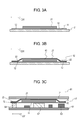
- FIG. 3A is a cross-sectional view of the heat conductive sheet according to the embodiment for illustrating a method of manufacturing the heat conductive sheet.
- FIG. 3B is a cross-sectional view of the heat conductive sheet according to the embodiment for illustrating the method of manufacturing the heat conductive sheet.
- FIG. 3C is a cross-sectional view of an electronic apparatus including the heat conductive sheet according to the embodiment for illustrating a method of manufacturing the electronic apparatus.
- FIG. 1A is a top view of electronic apparatus 81 including heat conductive sheet 51 according to an exemplary embodiment.
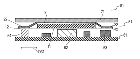
- FIG. 1B is a cross-sectional view of electronic apparatus 81 along line 1 B- 1 B shown in FIG. 1A .
- Heat conductive sheet 51 includes heat dissipating sheet 31 , heat insulating layer 41 provided on an upper surface of heat dissipating sheet 31 , sheet 21 provided on an upper surface of heat insulating layer 41 , and sheet 11 provided on a lower surface of heat dissipating sheet 31 .
- heat insulating layer 41 is provided above heat dissipating sheet 31
- sheet 21 is provided above heat insulating layer 41
- sheet 11 is provided below heat dissipating sheet 31 .
- Sheet 11 includes protruding portion 12 that protrudes, viewing from above, in surface directions D 31 parallel to the upper surface and the lower surface of heat dissipating sheet 31 .
- Protruding portion 12 surrounds, viewing from above, heat dissipating sheet 31 along outer periphery 31 C of heat dissipating sheet 31 .
- Sheet 21 includes protruding portion 22 that protrudes, viewing from above, in surface directions D 31 of heat dissipating sheet 31 .
- Protruding portion 22 surrounds, viewing from above, heat dissipating sheet 31 along outer periphery 31 C of heat dissipating sheet 31 .
- Protruding portions 12 and 22 may entirely surround heat dissipating sheet 31 viewing from above.
- the thermal conductivity of heat insulating layer 41 is lower than any of the thermal conductivity of sheet 11 , the thermal conductivity of sheet 21 , and the thermal conductivity of heat dissipating sheet 31 .
- Protruding portion 12 overlaps protruding portion 22 viewing from above.
- Heat conductive sheet 51 further includes heat insulating layer 42 contacting edge surface 32 heat dissipating sheet 31 .
- Edge surface 32 is connected to the upper surface and the lower surface of heat dissipating sheet 31 .
- Heat insulating layer 42 is surrounded by edge surface 32 of heat dissipating sheet 31 , the lower surface of sheet 11 , and the upper surface of sheet 21 .
- the thermal conductivity of heat insulating layer 42 is lower than any of the thermal conductivity of heat dissipating sheet 31 and sheets 11 and 12 .
- Mounting substrate 61 is provided below sheet 11 .
- Heat generating component 62 , electronic component 63 , and temperature dependent component 64 are mounted on mounting substrate 61 .
- Heat generating component 62 is joined to the lower surface of sheet 11 , and overlaps heat dissipating sheet 31 viewing from above.
- Electronic component 63 is not joined to the lower surface of sheet 11 .
- Temperature dependent component 64 is joined to the lower surface of sheet 11 , and does not overlap heat dissipating sheet 31 viewing from above.
- Liquid crystal panel 71 is provided above the upper surface of sheet 21 .
- Heat dissipating sheet 31 is a graphite sheet produced by thermally decomposing a polyimide resin.
- the thickness of heat dissipating sheet 31 is 0.05 mm.
- the thermal conductivity of heat dissipating sheet 31 along surface direction D 31 is about 1300 W/m ⁇ K.
- the thermal conductivity of heat dissipating sheet 31 along a direction perpendicular to surface direction D 31 is about 1/100 the thermal conductivity of heat dissipating sheet 31 along surface direction D 31 , that is, about 13 W/m ⁇ K.
- Heat dissipating sheet 31 may be made of a natural graphite sheet formed by compressing graphite powder.
- Sheet 11 is a double-sided adhesive tape containing an acrylic adhesive agent, and has a thickness of 0.01 mm.
- Sheet 11 may be a double-sided adhesive tape containing a silicone adhesive agent.
- Sheet 21 is made of polyethylene terephthalate (PET), and has a thickness of 0.01 mm. Sheet 21 may made of polyimide.
- Each of heat insulating layer 41 and heat insulating layer 42 may be implemented by a gap filled with air.
- the lower surface of sheet 21 is arranged so as to provide a gap from the upper surface of heat dissipating sheet 31 in a region outside heat dissipating sheet 31
- the lower surface of sheet 21 is arranged so as to have a gap (i.e., heat insulating layer 42 ) from the upper surface of sheet 11 .
- the thermal conductivity of air is lower than the thermal conductivity of the graphite sheet and the thermal conductivity of PET, so that heat insulating layers 41 and 42 containing air provide high thermal insulation effect.
- Heat insulating layers 41 and 42 are made of a material having a thermal conductivity lower than any of the thermal conductivities of sheet 11 , sheet 21 , and heat dissipating sheet 31 .
- heat insulating layer 41 and heat insulating layer 42 may be made of a urethane material other than air.
- Heat insulating layers 41 and 42 filled with air may partially communicate with each other.
- FIG. 2 is an enlarged cross-sectional view of heat conductive sheet 51 shown in FIG. 1B for illustrating a region near heat insulating layer 41 .
- Heat insulating layer 41 is a gap that is formed between sheet 21 and asperities 33 of heat dissipating sheet 31 and that is filled with air. Heat insulating layer 41 is formed in a layer configuration so as to be connected along surface directions D 31 of heat dissipating sheet 31 . Heat insulating layer 41 is formed by arranging sheet 21 on the upper surface of the heat dissipating sheet 31 having asperities 33 on a surface thereof.
- Heat generating component 62 may be implemented by, for example, a Central Processing Unit (CPU) which generates a large amount of heat in operation thereof. Heat generating component 62 is provided at a position overlapping heat dissipating sheet 31 viewing from above while sheet 11 is provided between heat generating component 62 and heat dissipating sheet 31 . Since liquid crystal panel 71 generally has low heat resistance, and may have color unevenness in a partial area of an image displayed on the panel due to an adverse effect of heat. Heat generating component 62 at the position overlapping heat dissipating sheet 31 viewing from above enables the heat generated by heat generating component 62 to efficiently dissipate to heat dissipating sheet 31 , and reduces the adverse effect of heat on liquid crystal panel 71 .
- CPU Central Processing Unit
- Temperature dependent component 64 is a component that has characteristics changing due to a temperature change. Temperature dependent component 64 includes a temperature compensated crystal oscillator (TCXO). Taking the adverse effect from heat into consideration, temperature dependent component 64 may be preferably disposed at a position away from heat generating component 62 , but may still have an adverse effect due to the heat transmitted from heat dissipating sheet 31 .
- TCXO temperature compensated crystal oscillator
- Heat conductive sheet 51 will be detailed below.
- the heat transmitted through the heat dissipating sheets may heat up various components, causing problems in the operations of the electronic apparatus.
- heat conductive sheet 51 In the heat conductive sheet disclosed in PTL 1, a protective layer and an adhesive layer contact an edge surface of a graphite sheet which has heat dissipation capability.
- heat insulating layer 42 contacts edge surface 32 of heat dissipating sheet 31 , and moreover, heat insulating layer 42 surrounds heat dissipating sheet 31 along the outer periphery of heat dissipating sheet 31 viewing from above. Therefore, heat conductive sheet 51 according to the exemplary embodiment can block the heat transmitted through heat dissipating sheet 31 in surface directions D 31 of heat dissipating sheet 31 .
- temperature dependent component 64 provided at the position that does not overlap heat dissipating sheet 31 viewing from above is unlikely to be affected by the heat transmitted from heat dissipating sheet 31 .
- heat conductive sheet 51 In the heat conductive sheet disclosed in PTL 2, a protective sheet and a graphite sheet having heat dissipation capability are joined with an adhesive agent.
- heat conductive sheet 51 according to the exemplary embodiment has heat insulating layer 41 provided between heat dissipating sheet 31 and sheet 11 . Therefore, liquid crystal panel 71 is not easily affected by heat.
- heat dissipating sheet 31 since the graphite sheet used for heat dissipating sheet 31 has electrical conductivity, the graphite sheet may cause a short circuit in the electronic apparatus if a part of the graphite sheet drops off.
- heat conductive sheet 51 according to the exemplary embodiment, heat dissipating sheet 31 is hermetically sealed by protruding portion 22 adhesive-bonded to protruding portion 12 made of a double-sided adhesive tape. Therefore, heat dissipating sheet 31 does not drop off in electronic apparatus 81 .
- protruding portions 12 and 22 may be heat-bonded to each other by heat-melting so as to hermetically seal heat dissipating sheet 31 .
- FIGS. 3A and 3B are flow-charts illustrating a method of manufacturing heat conductive sheet 51 .
- release sheet 91 made of PET is first prepared as illustrated in FIG. 3A .
- sheet 11 made of a double-sided adhesive tape is provided on the upper surface of release sheet 91 .
- heat dissipating sheet 31 made of a graphite sheet is provided on the upper surface of sheet 11 .
- Heat dissipating sheet 31 is provided such that sheet 11 includes protruding portion 12 protruding in surface directions D 31 of heat dissipating sheet 31 .
- Release sheet 91 is provided for improving handlability during manufacturing.
- sheet 21 is provided to cover an upper region of heat dissipating sheet 31 and includes include protruding portion 22 protruding in the surface directions of heat dissipating sheet 31 .
- Heat dissipating sheet 31 is hermetically sealed with protruding portion 22 adhesive bonded onto the upper surface of protruding portion 12 made of a double-sided adhesive tape.
- the position at which protruding portion 22 is adhesive-bonded to protruding portion 12 which is made of a double-sided adhesive tape is adjusted to adjust the thickness of heat insulating layer 41 which includes a gap, and to adjust the width of heat insulating layer 42 in surface direction D 31 of heat dissipating sheet 31 .
- Heat conductive sheet 51 may be manufactured through the above-described steps.
- FIG. 3C is a cross-sectional view of electronic apparatus 81 using heat conductive sheet 51 .
- heat generating component 62 is arranged below the lower surface of sheet 11 which is a double-sided adhesive tape exposed by peeling off release sheet 91 so as to overlap the heat dissipating sheet viewing from above. Further, temperature dependent component 64 is arranged below the lower surface of sheet 11 so as not to overlap the heat dissipating sheet viewing from above. Liquid crystal panel 71 is provided above the upper surface of sheet 21 . Electronic apparatus 81 including heat conductive sheet 51 may be manufactured in the above-described method.
- terms, such as “upper surface”, “lower surface”, “above”, “below”, and “viewing from above”, indicating directions merely indicate relative directions determined only by relative positional relationships among structural components of the heat conductive sheet [A4], and do not indicate absolute directions, such as a vertical direction.
- a heat conductive sheet according to the present disclosure can efficiently dissipate heat generated by heat generating components, and is therefore industrially useful.
Landscapes
- Physics & Mathematics (AREA)
- Nonlinear Science (AREA)
- Engineering & Computer Science (AREA)
- Thermal Sciences (AREA)
- Microelectronics & Electronic Packaging (AREA)
- Chemical & Material Sciences (AREA)
- Crystallography & Structural Chemistry (AREA)
- Mathematical Physics (AREA)
- General Physics & Mathematics (AREA)
- Optics & Photonics (AREA)
- Cooling Or The Like Of Electrical Apparatus (AREA)
- Cooling Or The Like Of Semiconductors Or Solid State Devices (AREA)
- Laminated Bodies (AREA)
- Materials Engineering (AREA)
Abstract
Description
- The present disclosure relates to a heat conductive sheet for dissipating heat generated from a heat generating component, and an electronic apparatus using the heat conductive sheet.
- As various types of electronic apparatuses have higher performance and more advanced functions, heat generating components in the apparatuses tend to generate a larger amount of heat. The heat generated from the heat generating component may affect adversely on the heat generating component or other electronic components of the heat generating component, and consequently may cause problems in operations of the electronic apparatus.
- A heat conductive sheet for transmitting the heat generated from the heat generating component is disclosed in, for example, PTL 1 and PTL 2.
- PTL 1 discloses a heat dissipating sheet having graphite, a protective layer, and a release sheet. The protective layer and the release sheet have respective protruding parts protruding in surface directions of graphite, and the protruding parts are joined to each other.
- PTL 2 discloses a heat dissipation sheet in which an edge surface and both main surfaces of graphite are covered with a heat conductive adhesive agent.
- PTL 1: Japanese Patent Laid-Open Publication No. 2014-061662
- PTL 2: Japanese Patent Laid-Open Publication No. 2010-010599
- A heat conductive sheet includes a heat dissipating sheet, a first heat insulating layer provided above the heat dissipating sheet, a first sheet provided above the first heat insulating layer, and a second sheet provided below the heat dissipating sheet. The first sheet includes a first protruding portion protruding from the heat dissipating sheet viewing from above. The second sheet includes a second protruding portion protruding from the heat dissipating sheet viewing from above. A thermal conductivity of the first heat insulating layer is lower than any of a thermal conductivity of the first sheet, a thermal conductivity of the second sheet, and a thermal conductivity of the heat dissipating sheet.
- This heat conductive sheet can dissipate heat efficiently.
-
FIG. 1A is a top view of an electronic apparatus including a heat conductive sheet according to an exemplary embodiment. -
FIG. 1B is a cross-sectional view of the electronic apparatus alongline 1B-1B shown inFIG. 1A . -
FIG. 2 is an enlarged cross-sectional view of the heat conductive sheet shown inFIG. 1B . -
FIG. 3A is a cross-sectional view of the heat conductive sheet according to the embodiment for illustrating a method of manufacturing the heat conductive sheet. -
FIG. 3B is a cross-sectional view of the heat conductive sheet according to the embodiment for illustrating the method of manufacturing the heat conductive sheet. -
FIG. 3C is a cross-sectional view of an electronic apparatus including the heat conductive sheet according to the embodiment for illustrating a method of manufacturing the electronic apparatus. - Each of the exemplary embodiments described below illustrates a specific example. The numerical values, shapes, materials, structural elements, arrangements and connections of the structural elements, etc. shown in the following exemplary embodiments are merely examples, and therefore do not limit the scope of the present invention. In addition, among the structural elements in the following exemplary embodiments, those not recited in any one of the independent claims which indicate the broadest inventive concepts are described as optional elements.
-
FIG. 1A is a top view ofelectronic apparatus 81 including heatconductive sheet 51 according to an exemplary embodiment.FIG. 1B is a cross-sectional view ofelectronic apparatus 81 alongline 1B-1B shown inFIG. 1A . - Heat
conductive sheet 51 includesheat dissipating sheet 31,heat insulating layer 41 provided on an upper surface ofheat dissipating sheet 31,sheet 21 provided on an upper surface ofheat insulating layer 41, andsheet 11 provided on a lower surface ofheat dissipating sheet 31. In other words,heat insulating layer 41 is provided aboveheat dissipating sheet 31,sheet 21 is provided aboveheat insulating layer 41, andsheet 11 is provided belowheat dissipating sheet 31. -
Sheet 11 includes protrudingportion 12 that protrudes, viewing from above, in surface directions D31 parallel to the upper surface and the lower surface ofheat dissipating sheet 31. Protrudingportion 12 surrounds, viewing from above,heat dissipating sheet 31 alongouter periphery 31C ofheat dissipating sheet 31.Sheet 21 includes protrudingportion 22 that protrudes, viewing from above, in surface directions D31 ofheat dissipating sheet 31. Protrudingportion 22 surrounds, viewing from above,heat dissipating sheet 31 alongouter periphery 31C ofheat dissipating sheet 31. Protrudingportions heat dissipating sheet 31 viewing from above. The thermal conductivity ofheat insulating layer 41 is lower than any of the thermal conductivity ofsheet 11, the thermal conductivity ofsheet 21, and the thermal conductivity ofheat dissipating sheet 31. Protrudingportion 12overlaps protruding portion 22 viewing from above. - Heat
conductive sheet 51 further includesheat insulating layer 42 contactingedge surface 32heat dissipating sheet 31.Edge surface 32 is connected to the upper surface and the lower surface ofheat dissipating sheet 31.Heat insulating layer 42 is surrounded byedge surface 32 ofheat dissipating sheet 31, the lower surface ofsheet 11, and the upper surface ofsheet 21. The thermal conductivity ofheat insulating layer 42 is lower than any of the thermal conductivity ofheat dissipating sheet 31 andsheets -
Mounting substrate 61 is provided belowsheet 11.Heat generating component 62,electronic component 63, and temperaturedependent component 64 are mounted onmounting substrate 61.Heat generating component 62 is joined to the lower surface ofsheet 11, and overlapsheat dissipating sheet 31 viewing from above.Electronic component 63 is not joined to the lower surface ofsheet 11. Temperaturedependent component 64 is joined to the lower surface ofsheet 11, and does not overlapheat dissipating sheet 31 viewing from above.Liquid crystal panel 71 is provided above the upper surface ofsheet 21. -
Heat dissipating sheet 31 is a graphite sheet produced by thermally decomposing a polyimide resin. The thickness ofheat dissipating sheet 31 is 0.05 mm. The thermal conductivity ofheat dissipating sheet 31 along surface direction D31 is about 1300 W/m·K. The thermal conductivity ofheat dissipating sheet 31 along a direction perpendicular to surface direction D31 is about 1/100 the thermal conductivity ofheat dissipating sheet 31 along surface direction D31, that is, about 13 W/m·K.Heat dissipating sheet 31 may be made of a natural graphite sheet formed by compressing graphite powder. -
Sheet 11 is a double-sided adhesive tape containing an acrylic adhesive agent, and has a thickness of 0.01 mm.Sheet 11 may be a double-sided adhesive tape containing a silicone adhesive agent. -
Sheet 21 is made of polyethylene terephthalate (PET), and has a thickness of 0.01 mm.Sheet 21 may made of polyimide. - Each of
heat insulating layer 41 and heat insulatinglayer 42 may be implemented by a gap filled with air. Specifically, the lower surface ofsheet 21 is arranged so as to provide a gap from the upper surface ofheat dissipating sheet 31 in a region outsideheat dissipating sheet 31, the lower surface ofsheet 21 is arranged so as to have a gap (i.e., heat insulating layer 42) from the upper surface ofsheet 11. The thermal conductivity of air is lower than the thermal conductivity of the graphite sheet and the thermal conductivity of PET, so thatheat insulating layers layers sheet 11,sheet 21, andheat dissipating sheet 31. For the materials ofsheet 11,sheet 21, andheat dissipating sheet 31 described above, heat insulatinglayer 41 and heat insulatinglayer 42 may be made of a urethane material other than air. - Heat insulating
layers -
FIG. 2 is an enlarged cross-sectional view of heatconductive sheet 51 shown inFIG. 1B for illustrating a region nearheat insulating layer 41. - Heat insulating
layer 41 is a gap that is formed betweensheet 21 andasperities 33 ofheat dissipating sheet 31 and that is filled with air. Heat insulatinglayer 41 is formed in a layer configuration so as to be connected along surface directions D31 ofheat dissipating sheet 31. Heat insulatinglayer 41 is formed by arrangingsheet 21 on the upper surface of theheat dissipating sheet 31 havingasperities 33 on a surface thereof. - Heat generating
component 62 may be implemented by, for example, a Central Processing Unit (CPU) which generates a large amount of heat in operation thereof. Heat generatingcomponent 62 is provided at a position overlappingheat dissipating sheet 31 viewing from above whilesheet 11 is provided betweenheat generating component 62 andheat dissipating sheet 31. Sinceliquid crystal panel 71 generally has low heat resistance, and may have color unevenness in a partial area of an image displayed on the panel due to an adverse effect of heat. Heat generatingcomponent 62 at the position overlappingheat dissipating sheet 31 viewing from above enables the heat generated byheat generating component 62 to efficiently dissipate to heat dissipatingsheet 31, and reduces the adverse effect of heat onliquid crystal panel 71. - Temperature
dependent component 64 is a component that has characteristics changing due to a temperature change. Temperaturedependent component 64 includes a temperature compensated crystal oscillator (TCXO). Taking the adverse effect from heat into consideration, temperaturedependent component 64 may be preferably disposed at a position away fromheat generating component 62, but may still have an adverse effect due to the heat transmitted fromheat dissipating sheet 31. - Heat
conductive sheet 51 will be detailed below. - In the heat dissipating sheets disclosed in PTL 1 and PTL 2, the heat transmitted through the heat dissipating sheets may heat up various components, causing problems in the operations of the electronic apparatus.
- In the heat conductive sheet disclosed in PTL 1, a protective layer and an adhesive layer contact an edge surface of a graphite sheet which has heat dissipation capability. On the other hand, in heat
conductive sheet 51 according to the exemplary embodiment, heat insulatinglayer 42contacts edge surface 32 ofheat dissipating sheet 31, and moreover, heat insulatinglayer 42 surroundsheat dissipating sheet 31 along the outer periphery ofheat dissipating sheet 31 viewing from above. Therefore, heatconductive sheet 51 according to the exemplary embodiment can block the heat transmitted throughheat dissipating sheet 31 in surface directions D31 ofheat dissipating sheet 31. - With the above-described structure, temperature
dependent component 64 provided at the position that does not overlapheat dissipating sheet 31 viewing from above is unlikely to be affected by the heat transmitted fromheat dissipating sheet 31. - In the heat conductive sheet disclosed in PTL 2, a protective sheet and a graphite sheet having heat dissipation capability are joined with an adhesive agent. On the other hand, heat
conductive sheet 51 according to the exemplary embodiment hasheat insulating layer 41 provided betweenheat dissipating sheet 31 andsheet 11. Therefore,liquid crystal panel 71 is not easily affected by heat. - In addition, since the graphite sheet used for
heat dissipating sheet 31 has electrical conductivity, the graphite sheet may cause a short circuit in the electronic apparatus if a part of the graphite sheet drops off. In heatconductive sheet 51 according to the exemplary embodiment,heat dissipating sheet 31 is hermetically sealed by protrudingportion 22 adhesive-bonded to protrudingportion 12 made of a double-sided adhesive tape. Therefore,heat dissipating sheet 31 does not drop off inelectronic apparatus 81. - Alternatively, protruding
portions heat dissipating sheet 31. - A method of manufacturing heat
conductive sheet 51 will be described below. -
FIGS. 3A and 3B are flow-charts illustrating a method of manufacturing heatconductive sheet 51. - In the method of manufacturing heat
conductive sheet 51,release sheet 91 made of PET is first prepared as illustrated inFIG. 3A . Then,sheet 11 made of a double-sided adhesive tape is provided on the upper surface ofrelease sheet 91. Next,heat dissipating sheet 31 made of a graphite sheet is provided on the upper surface ofsheet 11.Heat dissipating sheet 31 is provided such thatsheet 11 includes protrudingportion 12 protruding in surface directions D31 ofheat dissipating sheet 31. -
Release sheet 91 is provided for improving handlability during manufacturing. - Next, as illustrated in
FIG. 3B ,sheet 21 is provided to cover an upper region ofheat dissipating sheet 31 and includes include protrudingportion 22 protruding in the surface directions ofheat dissipating sheet 31.Heat dissipating sheet 31 is hermetically sealed with protrudingportion 22 adhesive bonded onto the upper surface of protrudingportion 12 made of a double-sided adhesive tape. In this case, the position at which protrudingportion 22 is adhesive-bonded to protrudingportion 12 which is made of a double-sided adhesive tape is adjusted to adjust the thickness ofheat insulating layer 41 which includes a gap, and to adjust the width ofheat insulating layer 42 in surface direction D31 ofheat dissipating sheet 31. - Heat
conductive sheet 51 may be manufactured through the above-described steps. - A method of manufacturing
electronic apparatus 81 including heatconductive sheet 51 will be described below.FIG. 3C is a cross-sectional view ofelectronic apparatus 81 using heatconductive sheet 51. - As illustrated in
FIG. 3C ,heat generating component 62 is arranged below the lower surface ofsheet 11 which is a double-sided adhesive tape exposed by peeling offrelease sheet 91 so as to overlap the heat dissipating sheet viewing from above. Further, temperaturedependent component 64 is arranged below the lower surface ofsheet 11 so as not to overlap the heat dissipating sheet viewing from above.Liquid crystal panel 71 is provided above the upper surface ofsheet 21.Electronic apparatus 81 including heatconductive sheet 51 may be manufactured in the above-described method. - In the exemplary embodiments, terms, such as “upper surface”, “lower surface”, “above”, “below”, and “viewing from above”, indicating directions merely indicate relative directions determined only by relative positional relationships among structural components of the heat conductive sheet [A4], and do not indicate absolute directions, such as a vertical direction.
- A heat conductive sheet according to the present disclosure can efficiently dissipate heat generated by heat generating components, and is therefore industrially useful.
-
- 11 sheet (first sheet)
- 12 protruding portion
- 21 sheet (second sheet)
- 22 protruding portion
- 31 heat dissipating sheet
- 32 edge surface
- 33 surface irregularities
- 41 heat insulating layer (first heat insulating layer)
- 42 heat insulating layer (second heat insulating layer)
- 51 heat conductive sheet
- 61 mounting substrate
- 62 heat generating component
- 63 electronic component
- 64 temperature dependent component
- 71 liquid crystal panel
- 81 electronic apparatus
- 91 release sheet
Claims (10)
Applications Claiming Priority (3)
| Application Number | Priority Date | Filing Date | Title |
|---|---|---|---|
| JP2015128250 | 2015-06-26 | ||
| JP2015-128250 | 2015-06-26 | ||
| PCT/JP2016/003025 WO2016208192A1 (en) | 2015-06-26 | 2016-06-23 | Heat conductive sheet and electronic apparatus using same |
Publications (2)
| Publication Number | Publication Date |
|---|---|
| US20180098461A1 true US20180098461A1 (en) | 2018-04-05 |
| US10244658B2 US10244658B2 (en) | 2019-03-26 |
Family
ID=57584770
Family Applications (1)
| Application Number | Title | Priority Date | Filing Date |
|---|---|---|---|
| US15/563,649 Active 2036-07-06 US10244658B2 (en) | 2015-06-26 | 2016-06-23 | Heat conductive sheet and electronic apparatus using same |
Country Status (4)
| Country | Link |
|---|---|
| US (1) | US10244658B2 (en) |
| JP (1) | JP6634610B2 (en) |
| CN (1) | CN107535076B (en) |
| WO (1) | WO2016208192A1 (en) |
Cited By (6)
| Publication number | Priority date | Publication date | Assignee | Title |
|---|---|---|---|---|
| CN112165840A (en) * | 2020-10-26 | 2021-01-01 | 华为技术有限公司 | Edge-wrapped heat sinks and electronic equipment |
| CN113365813A (en) * | 2019-02-08 | 2021-09-07 | 松下知识产权经营株式会社 | Thermally conductive sheet and electronic device using the same |
| EP3944010A1 (en) * | 2020-07-23 | 2022-01-26 | Ficosa Adas, S.L.U. | Display assembly for an imaging device |
| US11315852B2 (en) * | 2019-10-11 | 2022-04-26 | Aptiv Technologies Limited | Thermal interface layer for electronic device |
| ES2937844R1 (en) * | 2021-08-27 | 2023-04-10 | Ametek Inc | TEMPERATURE DEPENDENT ELECTRONIC COMPONENT HEATING SYSTEM |
| US12513871B2 (en) | 2021-02-17 | 2025-12-30 | Panasonic Intellectual Property Management Co., Ltd. | Image display device |
Citations (3)
| Publication number | Priority date | Publication date | Assignee | Title |
|---|---|---|---|---|
| US20060098412A1 (en) * | 2004-11-10 | 2006-05-11 | Sok-San Kim | Heat dissipation structure for display panel and display module equipped with the structure |
| US20100302231A1 (en) * | 2009-05-25 | 2010-12-02 | Chimei Innolux Corporation | Self-emission type display device with heat sink |
| US20140322848A1 (en) * | 2013-04-30 | 2014-10-30 | Samsung Display Co., Ltd. | Thermal transfer method and method of manufacturing an organic light emitting display device using the same |
Family Cites Families (9)
| Publication number | Priority date | Publication date | Assignee | Title |
|---|---|---|---|---|
| DE102005057136A1 (en) * | 2005-11-30 | 2007-06-06 | BSH Bosch und Siemens Hausgeräte GmbH | Housing for a refrigeration device |
| JP2008034474A (en) * | 2006-07-26 | 2008-02-14 | Sharp Corp | Heat transfer sheet and substrate device |
| JP2009094196A (en) * | 2007-10-05 | 2009-04-30 | Nec Corp | Heat dissipation structure for portable communication devices |
| JP2010010599A (en) | 2008-06-30 | 2010-01-14 | Fuji Polymer Industries Co Ltd | Heat diffusion sheet |
| JP2010251386A (en) * | 2009-04-10 | 2010-11-04 | Nec Corp | Electronic apparatus with thermal diffusion member, method of manufacturing electronic apparatus with thermal diffusion member, and thermal diffusion member |
| JP5586210B2 (en) * | 2009-11-13 | 2014-09-10 | 株式会社カネカ | Graphite film and graphite composite film |
| CN102480904A (en) * | 2010-11-24 | 2012-05-30 | 英业达股份有限公司 | Heat dissipation module and electronic device using same |
| JP6026831B2 (en) | 2012-09-21 | 2016-11-16 | 株式会社カネカ | Graphite composite film |
| EP2874479B1 (en) * | 2013-06-19 | 2018-08-08 | Amogreentech Co., Ltd. | Hybrid insulation sheet and electronic equipment comprising same |
-
2016
- 2016-06-23 JP JP2017524640A patent/JP6634610B2/en active Active
- 2016-06-23 US US15/563,649 patent/US10244658B2/en active Active
- 2016-06-23 WO PCT/JP2016/003025 patent/WO2016208192A1/en not_active Ceased
- 2016-06-23 CN CN201680025559.7A patent/CN107535076B/en active Active
Patent Citations (3)
| Publication number | Priority date | Publication date | Assignee | Title |
|---|---|---|---|---|
| US20060098412A1 (en) * | 2004-11-10 | 2006-05-11 | Sok-San Kim | Heat dissipation structure for display panel and display module equipped with the structure |
| US20100302231A1 (en) * | 2009-05-25 | 2010-12-02 | Chimei Innolux Corporation | Self-emission type display device with heat sink |
| US20140322848A1 (en) * | 2013-04-30 | 2014-10-30 | Samsung Display Co., Ltd. | Thermal transfer method and method of manufacturing an organic light emitting display device using the same |
Cited By (10)
| Publication number | Priority date | Publication date | Assignee | Title |
|---|---|---|---|---|
| CN113365813A (en) * | 2019-02-08 | 2021-09-07 | 松下知识产权经营株式会社 | Thermally conductive sheet and electronic device using the same |
| US12087661B2 (en) | 2019-02-08 | 2024-09-10 | Panasonic Intellectual Property Management Co., Ltd. | Heat conducting sheet and electronic device using same |
| US11315852B2 (en) * | 2019-10-11 | 2022-04-26 | Aptiv Technologies Limited | Thermal interface layer for electronic device |
| EP3944010A1 (en) * | 2020-07-23 | 2022-01-26 | Ficosa Adas, S.L.U. | Display assembly for an imaging device |
| US11903153B2 (en) | 2020-07-23 | 2024-02-13 | Ficosa Adas, S.L.U. | Display assembly for an imaging device |
| JP7609730B2 (en) | 2020-07-23 | 2025-01-07 | フィコサ アダス,ソシエダッド リミタダ ユニペルソナル | Display Assembly for Imaging Device |
| CN112165840A (en) * | 2020-10-26 | 2021-01-01 | 华为技术有限公司 | Edge-wrapped heat sinks and electronic equipment |
| WO2022089041A1 (en) * | 2020-10-26 | 2022-05-05 | 华为技术有限公司 | Edge-wrapped heat-dissipating sheet and electronic device |
| US12513871B2 (en) | 2021-02-17 | 2025-12-30 | Panasonic Intellectual Property Management Co., Ltd. | Image display device |
| ES2937844R1 (en) * | 2021-08-27 | 2023-04-10 | Ametek Inc | TEMPERATURE DEPENDENT ELECTRONIC COMPONENT HEATING SYSTEM |
Also Published As
| Publication number | Publication date |
|---|---|
| CN107535076B (en) | 2020-04-07 |
| CN107535076A (en) | 2018-01-02 |
| JP6634610B2 (en) | 2020-01-22 |
| US10244658B2 (en) | 2019-03-26 |
| WO2016208192A1 (en) | 2016-12-29 |
| JPWO2016208192A1 (en) | 2018-04-12 |
Similar Documents
| Publication | Publication Date | Title |
|---|---|---|
| US10244658B2 (en) | Heat conductive sheet and electronic apparatus using same | |
| US10748976B2 (en) | Method of manufacturing display device | |
| US11699670B2 (en) | High-frequency module | |
| JP5096782B2 (en) | Semiconductor device | |
| US8963315B2 (en) | Semiconductor device with surface electrodes | |
| JP6612723B2 (en) | Board device | |
| US20170238446A1 (en) | Display panel and display device | |
| EP3780921B1 (en) | Heat dissipation device for display panel, manufacturing method thereof, and display device | |
| KR101380320B1 (en) | Thermal conductive laminated member | |
| WO2018159453A1 (en) | Module | |
| CN106105025A (en) | Crystal oscillator with temperature chamber | |
| JP2013070224A5 (en) | Insulating substrate, vibration device and electronic device | |
| JP6962746B2 (en) | Image sensor mounting substrate, image pickup device and image pickup module | |
| JP2015084378A (en) | Electronic component, electronic apparatus, manufacturing method of mounting member, and manufacturing method of electronic component | |
| US11251768B2 (en) | Piezoelectric device | |
| KR101934573B1 (en) | Thermal conductive laminated material | |
| JP6208447B2 (en) | Electronic element storage package and electronic device | |
| US8217506B2 (en) | Semiconductor packaging structure having conductive gel to package semiconductor device | |
| JP4722514B2 (en) | Semiconductor device and insulating substrate for semiconductor device | |
| KR102485002B1 (en) | Heat-dissipating semiconductor package and method for manufacturing the same | |
| JP6548964B2 (en) | Substrate device | |
| JP6252412B2 (en) | Semiconductor device | |
| JP2007249014A (en) | Liquid crystal display device | |
| JP6673773B2 (en) | Wiring board | |
| JP2018018910A (en) | Wiring board |
Legal Events
| Date | Code | Title | Description |
|---|---|---|---|
| FEPP | Fee payment procedure |
Free format text: ENTITY STATUS SET TO UNDISCOUNTED (ORIGINAL EVENT CODE: BIG.); ENTITY STATUS OF PATENT OWNER: LARGE ENTITY |
|
| AS | Assignment |
Owner name: PANASONIC INTELLECTUAL PROPERTY MANAGEMENT CO., LT Free format text: ASSIGNMENT OF ASSIGNORS INTEREST;ASSIGNORS:MATSUNO, KOJI;KUBO, KAZUHIKO;SIGNING DATES FROM 20170905 TO 20170906;REEL/FRAME:044334/0759 |
|
| STCF | Information on status: patent grant |
Free format text: PATENTED CASE |
|
| MAFP | Maintenance fee payment |
Free format text: PAYMENT OF MAINTENANCE FEE, 4TH YEAR, LARGE ENTITY (ORIGINAL EVENT CODE: M1551); ENTITY STATUS OF PATENT OWNER: LARGE ENTITY Year of fee payment: 4 |