US20170194271A1 - Semiconductor package with three-dimensional antenna - Google Patents
Semiconductor package with three-dimensional antenna Download PDFInfo
- Publication number
- US20170194271A1 US20170194271A1 US15/335,226 US201615335226A US2017194271A1 US 20170194271 A1 US20170194271 A1 US 20170194271A1 US 201615335226 A US201615335226 A US 201615335226A US 2017194271 A1 US2017194271 A1 US 2017194271A1
- Authority
- US
- United States
- Prior art keywords
- region
- antenna
- package substrate
- structure portion
- semiconductor package
- Prior art date
- Legal status (The legal status is an assumption and is not a legal conclusion. Google has not performed a legal analysis and makes no representation as to the accuracy of the status listed.)
- Granted
Links
Images


Classifications
-
- H—ELECTRICITY
- H10—SEMICONDUCTOR DEVICES; ELECTRIC SOLID-STATE DEVICES NOT OTHERWISE PROVIDED FOR
- H10W—GENERIC PACKAGES, INTERCONNECTIONS, CONNECTORS OR OTHER CONSTRUCTIONAL DETAILS OF DEVICES COVERED BY CLASS H10
- H10W74/00—Encapsulations, e.g. protective coatings
- H10W74/10—Encapsulations, e.g. protective coatings characterised by their shape or disposition
- H10W74/111—Encapsulations, e.g. protective coatings characterised by their shape or disposition the semiconductor body being completely enclosed
-
- H01L23/66—
-
- H—ELECTRICITY
- H10—SEMICONDUCTOR DEVICES; ELECTRIC SOLID-STATE DEVICES NOT OTHERWISE PROVIDED FOR
- H10W—GENERIC PACKAGES, INTERCONNECTIONS, CONNECTORS OR OTHER CONSTRUCTIONAL DETAILS OF DEVICES COVERED BY CLASS H10
- H10W44/00—Electrical arrangements for controlling or matching impedance
- H10W44/20—Electrical arrangements for controlling or matching impedance at high-frequency [HF] or radio frequency [RF]
-
- H01L23/3128—
-
- H01L23/552—
-
- H—ELECTRICITY
- H01—ELECTRIC ELEMENTS
- H01Q—ANTENNAS, i.e. RADIO AERIALS
- H01Q1/00—Details of, or arrangements associated with, antennas
- H01Q1/12—Supports; Mounting means
- H01Q1/22—Supports; Mounting means by structural association with other equipment or articles
- H01Q1/2283—Supports; Mounting means by structural association with other equipment or articles mounted in or on the surface of a semiconductor substrate as a chip-type antenna or integrated with other components into an IC package
-
- H—ELECTRICITY
- H01—ELECTRIC ELEMENTS
- H01Q—ANTENNAS, i.e. RADIO AERIALS
- H01Q1/00—Details of, or arrangements associated with, antennas
- H01Q1/52—Means for reducing coupling between antennas; Means for reducing coupling between an antenna and another structure
- H01Q1/526—Electromagnetic shields
-
- H—ELECTRICITY
- H10—SEMICONDUCTOR DEVICES; ELECTRIC SOLID-STATE DEVICES NOT OTHERWISE PROVIDED FOR
- H10W—GENERIC PACKAGES, INTERCONNECTIONS, CONNECTORS OR OTHER CONSTRUCTIONAL DETAILS OF DEVICES COVERED BY CLASS H10
- H10W42/00—Arrangements for protection of devices
-
- H—ELECTRICITY
- H10—SEMICONDUCTOR DEVICES; ELECTRIC SOLID-STATE DEVICES NOT OTHERWISE PROVIDED FOR
- H10W—GENERIC PACKAGES, INTERCONNECTIONS, CONNECTORS OR OTHER CONSTRUCTIONAL DETAILS OF DEVICES COVERED BY CLASS H10
- H10W42/00—Arrangements for protection of devices
- H10W42/20—Arrangements for protection of devices protecting against electromagnetic or particle radiation, e.g. light, X-rays, gamma-rays or electrons
-
- H—ELECTRICITY
- H10—SEMICONDUCTOR DEVICES; ELECTRIC SOLID-STATE DEVICES NOT OTHERWISE PROVIDED FOR
- H10W—GENERIC PACKAGES, INTERCONNECTIONS, CONNECTORS OR OTHER CONSTRUCTIONAL DETAILS OF DEVICES COVERED BY CLASS H10
- H10W42/00—Arrangements for protection of devices
- H10W42/60—Arrangements for protection of devices protecting against electrostatic charges or discharges, e.g. Faraday shields
-
- H—ELECTRICITY
- H10—SEMICONDUCTOR DEVICES; ELECTRIC SOLID-STATE DEVICES NOT OTHERWISE PROVIDED FOR
- H10W—GENERIC PACKAGES, INTERCONNECTIONS, CONNECTORS OR OTHER CONSTRUCTIONAL DETAILS OF DEVICES COVERED BY CLASS H10
- H10W70/00—Package substrates; Interposers; Redistribution layers [RDL]
- H10W70/60—Insulating or insulated package substrates; Interposers; Redistribution layers
- H10W70/67—Insulating or insulated package substrates; Interposers; Redistribution layers characterised by their insulating layers or insulating parts
- H10W70/68—Shapes or dispositions thereof
- H10W70/685—Shapes or dispositions thereof comprising multiple insulating layers
-
- H—ELECTRICITY
- H10—SEMICONDUCTOR DEVICES; ELECTRIC SOLID-STATE DEVICES NOT OTHERWISE PROVIDED FOR
- H10W—GENERIC PACKAGES, INTERCONNECTIONS, CONNECTORS OR OTHER CONSTRUCTIONAL DETAILS OF DEVICES COVERED BY CLASS H10
- H10W74/00—Encapsulations, e.g. protective coatings
- H10W74/10—Encapsulations, e.g. protective coatings characterised by their shape or disposition
- H10W74/111—Encapsulations, e.g. protective coatings characterised by their shape or disposition the semiconductor body being completely enclosed
- H10W74/114—Encapsulations, e.g. protective coatings characterised by their shape or disposition the semiconductor body being completely enclosed by a substrate and the encapsulations
- H10W74/117—Encapsulations, e.g. protective coatings characterised by their shape or disposition the semiconductor body being completely enclosed by a substrate and the encapsulations the substrate having spherical bumps for external connection
-
- H01L2223/6677—
-
- H—ELECTRICITY
- H10—SEMICONDUCTOR DEVICES; ELECTRIC SOLID-STATE DEVICES NOT OTHERWISE PROVIDED FOR
- H10W—GENERIC PACKAGES, INTERCONNECTIONS, CONNECTORS OR OTHER CONSTRUCTIONAL DETAILS OF DEVICES COVERED BY CLASS H10
- H10W44/00—Electrical arrangements for controlling or matching impedance
- H10W44/20—Electrical arrangements for controlling or matching impedance at high-frequency [HF] or radio frequency [RF]
- H10W44/241—Electrical arrangements for controlling or matching impedance at high-frequency [HF] or radio frequency [RF] for passive devices or passive elements
- H10W44/248—Electrical arrangements for controlling or matching impedance at high-frequency [HF] or radio frequency [RF] for passive devices or passive elements for antennas
-
- H—ELECTRICITY
- H10—SEMICONDUCTOR DEVICES; ELECTRIC SOLID-STATE DEVICES NOT OTHERWISE PROVIDED FOR
- H10W—GENERIC PACKAGES, INTERCONNECTIONS, CONNECTORS OR OTHER CONSTRUCTIONAL DETAILS OF DEVICES COVERED BY CLASS H10
- H10W72/00—Interconnections or connectors in packages
- H10W72/20—Bump connectors, e.g. solder bumps or copper pillars; Dummy bumps; Thermal bumps
- H10W72/251—Materials
- H10W72/252—Materials comprising solid metals or solid metalloids, e.g. PbSn, Ag or Cu
-
- H—ELECTRICITY
- H10—SEMICONDUCTOR DEVICES; ELECTRIC SOLID-STATE DEVICES NOT OTHERWISE PROVIDED FOR
- H10W—GENERIC PACKAGES, INTERCONNECTIONS, CONNECTORS OR OTHER CONSTRUCTIONAL DETAILS OF DEVICES COVERED BY CLASS H10
- H10W90/00—Package configurations
- H10W90/701—Package configurations characterised by the relative positions of pads or connectors relative to package parts
- H10W90/721—Package configurations characterised by the relative positions of pads or connectors relative to package parts of bump connectors
- H10W90/724—Package configurations characterised by the relative positions of pads or connectors relative to package parts of bump connectors between a chip and a stacked insulating package substrate, interposer or RDL
Definitions
- the present invention relates to semiconductor package technology, and in particular to a semiconductor package with a three-dimensional (3D) antenna.
- ⁇ ⁇ ⁇ ⁇ ⁇ ⁇ ⁇ ⁇ ⁇ ⁇ ⁇ ⁇ ⁇ ⁇ ⁇ ⁇ ⁇ ⁇ ⁇ ⁇ ⁇ ⁇ ⁇ ⁇ ⁇ ⁇ ⁇ ⁇ ⁇ ⁇ ⁇ ⁇ ⁇ ⁇ ⁇ ⁇ ⁇ ⁇ ⁇ ⁇ ⁇ ⁇ ⁇ ⁇ ⁇ ⁇ ⁇ ⁇ ⁇ ⁇ ⁇ ⁇ ⁇ ⁇ ⁇ ⁇ ⁇ ⁇ ⁇ ⁇ ⁇ ⁇ ⁇ ⁇ ⁇ ⁇ ⁇ ⁇ ⁇ ⁇ ⁇ ⁇ ⁇ ⁇ ⁇ ⁇ ⁇ ⁇ ⁇ ⁇ ⁇ ⁇ ⁇ ⁇ ⁇ ⁇ ⁇ ⁇ ⁇ ⁇ ⁇ ⁇ ⁇ ⁇ ⁇ ⁇ ⁇ ⁇ ⁇ ⁇ ⁇ ⁇ ⁇ ⁇ ⁇ ⁇ ⁇ ⁇ ⁇ ⁇ ⁇ ⁇ ⁇ ⁇ ⁇ ⁇ ⁇ ⁇ ⁇ ⁇ ⁇ ⁇ ⁇ ⁇ ⁇ ⁇
- the antenna is not incorporated therein. Namely, the antenna and the IC package are manufactured separately and are electrically connected after being mounted on a circuit board. As a result, the manufacturing cost is increased and it is difficult to achieve a compact and small SiP component.
- EMI electromagnetic interference
- signal coupling between the antenna and different parts of the chip or package may easily occur. These can result in a reduction of the antenna's level of performance.
- a novel semiconductor package is desirable.
- An exemplary embodiment of a semiconductor package includes a package substrate having a first region and a second region defined between an edge of the package substrate and an edge of the first region.
- a semiconductor die is disposed on the package substrate in the first region.
- a conductive shielding element is disposed on the package substrate and covers the semiconductor die.
- a 3D antenna includes a planar structure portion disposed on the package substrate in the second region. The 3D antenna further includes a bridge structure portion above the planar structure portion and connected thereto.
- a molding compound encapsulates the conductive shielding element and the 3D antenna.
- a semiconductor package includes a package substrate having a first region and a second region defined between an edge of the package substrate and an edge of the first region.
- a molding compound is disposed on the package substrate in the first and second regions.
- a semiconductor die is disposed on the package substrate in the first region and inside the molding compound.
- a 3D antenna includes a planar structure portion on the package substrate in the second region.
- the 3D antenna further includes a wall structure portion contacting the planar structure portion and covering a top surface or one of sidewalls of the molding compound in the second region.
- a conductive shielding element includes a spacer portion between the 3D antenna and the semiconductor die and passing through the molding compound.
- the conductive shielding element further includes a U-shaped wall portion covering the sidewalls of the molding compound in the first region and separated from the wall structure portion of the 3D antenna.
- An exemplary embodiment of a semiconductor package assembly includes a printed circuit board (PCB) having a keep-out region.
- a package substrate is disposed on the PCB.
- the semiconductor package includes a package substrate having a first region and a second region defined between an edge of the package substrate and an edge of the first region.
- a semiconductor die is disposed on the package substrate in the first region.
- a conductive shielding element is disposed on the package substrate and covers the semiconductor die.
- a 3D antenna includes a planar structure portion disposed on the package substrate in the second region. The 3D antenna further includes a bridge structure portion above the planar structure portion and connected thereto.
- a molding compound encapsulates the conductive shielding element and the 3D antenna.
- a semiconductor package assembly includes a PCB having a keep-out region.
- a package substrate is disposed on the PCB.
- the semiconductor package includes a package substrate having a first region and a second region defined between an edge of the package substrate and an edge of the first region.
- a molding compound is disposed on the package substrate in the first and second regions.
- a semiconductor die is disposed on the package substrate in the first region and inside the molding compound.
- a 3D antenna includes a planar structure portion on the package substrate in the second region.
- the 3D antenna further includes a wall structure portion contacting the planar structure portion and covering a top surface or one of sidewalls of the molding compound in the second region.
- a conductive shielding element includes a spacer portion between the 3D antenna and the semiconductor die and passing through the molding compound.
- the conductive shielding element further includes a U-shaped wall portion covering the sidewalls of the molding compound in the first region and separated from the wall structure portion of the 3D antenna.
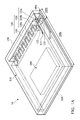
- FIG. 1A is a perspective view of an exemplary semiconductor package in accordance with some embodiments of the disclosure.
- FIG. 1B is a partial plan view of the exemplary semiconductor package shown in FIG. 1A .
- FIG. 1C is a cross-sectional view of an exemplary semiconductor package shown in FIG. 1A .
- FIG. 2 is a cross-sectional view of an exemplary semiconductor package assembly in accordance with some embodiments of the disclosure.
- FIG. 3A is a perspective view of an exemplary semiconductor package in accordance with some embodiments of the disclosure.
- FIG. 3B is a partial plan view of the exemplary semiconductor package shown in FIG. 3A .
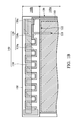
- FIG. 3C is a cross-sectional view of an exemplary semiconductor package shown in FIG. 3A .
- FIG. 4 is a cross-sectional view of an exemplary semiconductor package assembly in accordance with some embodiments of the disclosure.
- FIG. 1A is a perspective view of a semiconductor package 10 in accordance with some embodiments of the disclosure
- FIG. 1B is a partial plan view of the exemplary semiconductor package shown in FIG. 1A
- FIG. 1C is a cross-sectional view of an exemplary semiconductor package shown in FIG. 1A
- the semiconductor package 10 is a flip-chip semiconductor package.
- the semiconductor package 10 may be a system in package (SiP) package with an integrated antenna, such as an antenna on package (AoP) or antenna in package (AiP).
- the semiconductor package 10 includes a package substrate 100 having a first region 100 a and a second region 100 b , as shown in FIG. 1C .
- the second region 100 b is defined between an edge 100 e of the package substrate 100 and an edge of the first region 100 a ′ and has an area that is smaller than that of the first region 100 a .
- the package substrate 100 may be mounted on a base (not shown), such as a PCB, by a bonding process.
- the package substrate 100 includes conductive structures 101 that are mounted on and electrically coupled to the base in the bonding process.
- the conductive structures 101 include a conductive bump structure (such as a copper or solder bump structure), a conductive pillar structure, a conductive wire structure or a conductive paste structure.
- the semiconductor package 10 further includes a semiconductor die 200 disposed on the package substrate 100 in the first region 100 a .
- the semiconductor die 200 may be mounted on the package substrate 100 by a bonding process.
- the semiconductor die 200 includes conductive structures 201 that are mounted on and electrically coupled to the package substrate 100 in the bonding process.
- the conductive structures 201 may include a conductive bump structure (such as a copper or solder bump structure), a conductive pillar structure, or a conductive paste structure.
- the semiconductor die may be a system on chip (SOC) die and include a radio frequency (RF) device (not shown) therein.
- SOC system on chip
- RF radio frequency
- the semiconductor package 10 further includes a conductive shielding element 110 disposed on the package substrate 100 and covers the semiconductor die 200 .
- the conductive shielding element 110 is formed of copper, aluminum or another suitable shielding material to provide EMI protection.
- the conductive shielding element 110 includes a plate portion and sidewall portions surrounding the edges of the plate portion, so that the semiconductor die 200 is inside the space created by the conductive shielding element 110 and the package substrate 100 .
- the conductive shielding element 110 has an opening 122 formed in one of the sidewall portions thereof.
- the sidewall portion that extends along the edge 100 a ′ (indicated in FIG. 1C ) of the package substrate 100 has an opening 122 (indicated in FIG. 1A ).
- the opening 122 allows one or more devices formed in the semiconductor package 10 to pass through the conductive shielding element 110 .
- an antenna may pass through the conductive shielding element 110 via the opening 122 .
- the semiconductor package 10 further includes a 3D antenna 140 disposed on the package substrate 100 .
- the 3D antenna 140 may include a planar structure portion 120 and a bridge structure portion 130 .
- the planar structure portion 120 is disposed on the package substrate 100 in the second region 100 b .
- the bridge structure portion 130 is disposed above the planar structure portion 120 and connected thereto.
- the planar structure portion 120 of the 3D antenna 140 includes a folded pattern 120 a and first and second bar patterns 120 b and 120 c connected thereto, as shown in FIGS. 1A and 1B .
- the folded pattern 120 a of the planar structure portion 120 is entirely located at the second region 100 b of the package substrate 100 .
- the first bar pattern 120 b and the second bar pattern 120 c of the planar structure portion 120 are located at both first and second regions 100 a and 100 b of the package substrate 100 .
- the first bar pattern 120 b is extended from the folded pattern 120 a of the planar structure portion 120 and passes through the opening 122 of the conductive shielding element 110 , such that the first bar pattern 120 b of the planar structure portion 120 has an end 121 in the first region 100 a of the package substrate 100 .
- the second bar pattern 120 c is also extended from the folded pattern 120 a of the planar structure portion 120 to the first region 100 a of the package substrate 100 , such that the second bar pattern 120 c of the planar structure portion 120 has an end 121 ′ in the first region 100 a of the package substrate 100 .
- the end 121 of the first bar pattern 120 b of the planar structure portion 120 serves as a feeding point of the 3D antenna 140 .
- the second bar pattern 120 c is grounded (not shown) via the package substrate 100 and may be parallel to the first bar pattern 120 b.
- the bridge structure portion 130 of the 3D antenna 140 is also entirely located at the second region 100 b of the package substrate 100 and has an inverted U shape, as shown in FIG. 1A .
- the inverted U-shaped bridge structure portion 130 may include a first end that is connected to and above the folded pattern 120 a of the planar structure portion 120 and a second end supported by the package substrate 100 .
- the inverted U-shaped bridge structure portion 130 may have a lateral extending portion 130 a (as indicated in FIG. 1C ) that is parallel to the first and second bar patterns 120 b and 120 c of the planar structure portion 120 and has an end 135 to serve as an open end of the 3D antenna 140 .
- the bridge structure portion 130 allows for the formation of a 3D antenna, so as to increase the effective length of the 3D antenna 140 . As a result, a desired operation frequency for the antenna can be obtained.
- the shape of the bridge structure and of the planar structure portion of the 3D antenna may be varied by design demands and are not limited to the embodiment shown in FIGS. 1A to 1C .
- the semiconductor package 10 further includes a molding compound 150 disposed on the package substrate 100 and entirely encapsulates the conductive shielding element 110 and the 3D antenna 140 thereon.
- the molding compound 150 may be formed of an epoxy, a resin, a moldable polymer, or the like
- the semiconductor package assembly 20 includes a semiconductor package 10 shown in FIGS. 1A to 1C .
- the semiconductor package 10 is disposed on a circuit board 300 (e.g., a printed circuit board (PCB) that may be formed of polypropylene (PP)).
- PCB printed circuit board
- PP polypropylene
- the semiconductor package 10 is mounted on the circuit board 300 by the conductive structures 101 of the package substrate 100 using a bonding process.
- the circuit board 300 (e.g., the PCB) has a keep-out region 300 a that is a region free of conductive traces or elements formed therein.
- the semiconductor package 10 is disposed on the circuit board 300 in an arrangement wherein the second region 100 b of the package substrate 100 corresponds to the keep-out region 300 a of the circuit board 300 . Namely, the second region 100 b overlaps with the keep-out region 300 a .
- the keep-out region 300 a is located near an edge 300 e of the circuit board 300 , such that the 3D antenna 140 is disposed near the edge 300 e of the circuit board 300 .
- a conductive shielding element and a 3D antenna are integrated into a semiconductor package for fabricating an antenna in package (AiP). Since the 3D antenna is incorporated into the semiconductor package, the manufacturing cost is reduced and it allows for achieving a small, compact SiP component.
- the bridge structure portion of the 3D antenna increases its effective length further.
- the 3D antenna is embedded in the molding compound, design flexibility for the system integration of the semiconductor package can be increased.
- the conductive shielding element provides an EMI protection for the semiconductor package and prevents signal coupling between the antenna and semiconductor die that is inside the conductive shielding element.
- FIG. 3A is a perspective view of a semiconductor package 10 ′ in accordance with some embodiments of the disclosure
- FIG. 3B is a partial plan view of the exemplary semiconductor package shown in FIG. 3A
- FIG. 3C is a cross-sectional view of an exemplary semiconductor package shown in FIG. 3A .
- Descriptions of elements of the embodiments hereinafter that are the same as or similar to those previously described with reference to FIGS. 1A to 1C are omitted for brevity.
- the semiconductor package 10 ′ has a structure that is similar to that of the semiconductor package 10 shown in FIGS. 1A to 1C except for the structure and the arrangement of the conductive shielding element and the 3D antenna.
- the semiconductor package 10 ′ includes a molding compound 150 disposed on a package substrate 100 in the first and second regions 100 a and 100 b . Moreover, a semiconductor die 200 disposed on the package substrate 100 in the first region 100 a and inside the molding compound 150 .
- the semiconductor package 10 ′ further includes a 3D antenna 340 disposed on the package substrate 100 .
- the 3D antenna 340 includes a planar structure portion 320 and a wall structure portion 330 contacting the planar structure portion 320 .
- the planar structure portion 320 is disposed on the package substrate 100 in the second region 100 b .
- the wall structure portion 330 covers one or more sidewalls 150 a , 150 c , and 150 d of the molding compound 150 in the second region 100 b (e.g., the sidewall 150 a indicated in FIGS. 3A and 3C that is near the edge 100 e of the package substrate 100 ).
- the wall structure portion 330 may cover the top surface of the molding compound 150 in the second region 100 b.
- the planar structure portion 320 of the 3D antenna 140 includes a spiral pattern 320 a and two bar patterns 320 b and 320 c separated therefrom, as shown in FIGS. 3A and 3B .
- the spiral pattern 320 a of the planar structure portion 320 is entirely located at the second region 100 b of the package substrate 100 and has an end 325 to serve as an open end of the 3D antenna 340 .
- the bar pattern 320 b of the planar structure portion 120 is T-shaped and located at both first and second regions 100 a and 100 b of the package substrate 100 .
- the bar pattern 320 b e.g., T-bar pattern
- the bar pattern 320 b has a stem portion extending from the second region 100 b of the package substrate 100 to the first region 100 a thereof.
- the stem portion of the bar pattern 320 b has an end 321 in the first region 100 a of the package substrate 100 .
- the end 321 of the bar pattern 320 b of the planar structure portion 320 serves as a feeding point of the 3D antenna 340 .
- the bar pattern 320 b (e.g., T-bar pattern) has an arm portion.
- the bar pattern 320 c is extended from the arm portion of the bar pattern 320 b and may be parallel to the stem portion of the bar pattern 320 b .
- the bar pattern 320 c is located at second region 100 b of the package substrate 100 and may be grounded (not shown) via the package substrate 100 .
- the 3D antenna 340 may further include first and second conductive vias 103 and 105 (indicated in FIGS. 3A and 3C ) that are disposed in the package substrate 100 in the second region 100 b and electrically connected to the spiral pattern 320 a and the bar pattern 320 b , respectively.
- each of the first and second conductive vias 103 and 105 has a sidewall level with the edge 100 e of the package substrate 100 , such that the sidewalls of the first and second conductive vias 103 and 105 are exposed from the edge 100 e of the package substrate 100 .
- the wall structure portion 330 of the 3D antenna 340 may further cover the sidewall of the package substrate 100 that is at the edge 100 e of the package substrate 100 , so that the exposed sidewalls of the first and second conductive vias 103 and 105 contact the wall structure portion 330 of the 3D antenna 340 .
- the first conductive via 103 is electrically connected between the spiral pattern 320 a and the wall structure portion 330 and the second conductive via 105 is electrically connected between the bar pattern 320 b and the wall structure portion 330 .
- the wall structure portion 330 allows for the formation of a 3D antenna, so as to increase the effective length. As a result, a desired operation frequency for the antenna can be obtained.
- planar structure portion of the 3D antenna may be varied by design demands and is not limited to the embodiment shown in FIGS. 3A to 3C .
- the semiconductor package 10 ′ further includes a conductive shielding element 310 disposed on the package substrate 100 to cover the semiconductor die 200 .
- the conductive shielding element 310 is formed of copper, aluminum or another suitable shielding material to provide an EMI protection.
- the conductive shielding element 310 may be formed of a material that is the same as that of the wall structure portion 330 of the 3D antenna 340 .
- the conductive shielding element 310 includes a spacer portion 301 , a U-shaped wall portion 303 , and a plate portion 305 .
- the spacer portion 301 of the conductive shielding element 310 is disposed on the package substrate 100 and extends along the edge 100 a ′ (indicated in FIG. 3C ) of the package substrate 100 .
- the spacer portion 301 of the conductive shielding element 310 is disposed between the 3D antenna 340 and the semiconductor die 200 and passes through the molding compound 105 , such that the top surface of the spacer portion 301 is exposed from the molding compound 105 .
- sidewalls of the spacer portion 301 may also be exposed from the sidewalls 105 c and 105 d (indicated in FIG. 3A ) of the molding compound 105 .
- the spacer portion 301 of the conductive shielding element 310 has an opening 301 a formed therein.
- the opening 301 a allows one or more devices formed in the semiconductor package 10 to pass through the conductive shielding element 110 .
- the bar pattern 320 b of the planar structure portion 320 of the 3D antenna 340 may pass through the spacer portion 301 of the conductive shielding element 110 via the opening 301 a.
- the U-shaped wall portion 303 covers the sidewalls 150 b , 150 c , and 150 d of the molding compound 150 in the first region 100 a and is separated from the wall structure portion 330 of the 3D antenna 340 . Namely, portions of the sidewalls 150 c and 150 d may be exposed from the U-shaped wall portion 303 .
- the plate portion 305 partially covers a top surface of the molding compound 105 in the first region 100 a , so that the plate portion 305 is connected to the exposed top surface of the spacer portion 301 . Similarly, the plate portion 305 is separated from the wall structure portion 330 of the 3D antenna 340 . Namely, a portion of the top surface of the molding compound 105 may be exposed from the plate portion 305 .
- the semiconductor package assembly 20 ′ includes a semiconductor package 10 ′ shown in FIGS. 3A to 3C .
- the semiconductor package 10 ′ is disposed on a circuit board 300 .
- the semiconductor package 10 ′ is mounted on the circuit board 300 by the conductive structures 101 of the package substrate 100 using a bonding process.
- the semiconductor package 10 ′ is disposed on the circuit board 300 in an arrangement wherein the second region 100 b of the package substrate 100 corresponds to the keep-out region 300 a of the circuit board 300 . Namely, the second region 100 b overlaps with the keep-out region 300 a .
- the keep-out region 300 a is located near an edge 300 e of the circuit board 300 , such that the 3D antenna 340 is disposed near the edge 300 e of the circuit board 300 .
- a conductive shielding element and a 3D antenna are integrated into a semiconductor package for fabricating an antenna in package (AiP). Since the 3D antenna is incorporated into the semiconductor package, the manufacturing cost is reduced and it allows for achieving a small, compact SiP component.
- the wall structure portion of the 3D antenna increases its effective length. As a result, a desired operation frequency for the antenna can be obtained.
- the 3D antenna is integrated in the semiconductor package, design flexibility for the system integration of the semiconductor package can be increased.
- the conductive shielding element provides EMI protection for the semiconductor package and prevents signal coupling between the antenna and semiconductor die that is inside the conductive shielding element.
Landscapes
- Physics & Mathematics (AREA)
- Electromagnetism (AREA)
- Engineering & Computer Science (AREA)
- Microelectronics & Electronic Packaging (AREA)
- Shielding Devices Or Components To Electric Or Magnetic Fields (AREA)
- Structures Or Materials For Encapsulating Or Coating Semiconductor Devices Or Solid State Devices (AREA)
- Health & Medical Sciences (AREA)
- Toxicology (AREA)
- Details Of Aerials (AREA)
- Support Of Aerials (AREA)
Abstract
Description
- This application claims the benefit of U.S. Provisional Application No. 62/275,280 filed on Jan. 6, 2016, the entirety of which is incorporated by reference herein.
- Field of the Invention
- The present invention relates to semiconductor package technology, and in particular to a semiconductor package with a three-dimensional (3D) antenna.
- Description of the Related Art
- In recent years, the semiconductor industry has seen a trend towards the so-called system in package (SiP) concept. The integration of systems integrated into a single integrated circuit (IC) package provides several advantages in terms of cost, size, performance, and product-design flexibility.
- Many handheld electronic products, such as handheld computers, mobile phones, personal digital assistants (PDAs), and digital cameras, or media players, often include SiP components. These handheld electronic products are also provided with wireless communications capabilities. For achieving the function of wireless communications, an antenna and a communication module (e.g., an IC package with radio frequency (RF) devices) are typically required. The antenna is used for transmitting and receiving signals from the communication module.
- In the conventional design of an IC package (e.g., the communication module), the antenna is not incorporated therein. Namely, the antenna and the IC package are manufactured separately and are electrically connected after being mounted on a circuit board. As a result, the manufacturing cost is increased and it is difficult to achieve a compact and small SiP component.
- Although the incorporation of an antenna into a typical IC package has been proposed, electromagnetic interference (EMI) and signal coupling between the antenna and different parts of the chip or package may easily occur. These can result in a reduction of the antenna's level of performance. Thus, a novel semiconductor package is desirable.
- Semiconductor packages are provided. An exemplary embodiment of a semiconductor package includes a package substrate having a first region and a second region defined between an edge of the package substrate and an edge of the first region. A semiconductor die is disposed on the package substrate in the first region. A conductive shielding element is disposed on the package substrate and covers the semiconductor die. A 3D antenna includes a planar structure portion disposed on the package substrate in the second region. The 3D antenna further includes a bridge structure portion above the planar structure portion and connected thereto. A molding compound encapsulates the conductive shielding element and the 3D antenna.
- Another exemplary embodiment of a semiconductor package includes a package substrate having a first region and a second region defined between an edge of the package substrate and an edge of the first region. A molding compound is disposed on the package substrate in the first and second regions. A semiconductor die is disposed on the package substrate in the first region and inside the molding compound. A 3D antenna includes a planar structure portion on the package substrate in the second region. The 3D antenna further includes a wall structure portion contacting the planar structure portion and covering a top surface or one of sidewalls of the molding compound in the second region. A conductive shielding element includes a spacer portion between the 3D antenna and the semiconductor die and passing through the molding compound. The conductive shielding element further includes a U-shaped wall portion covering the sidewalls of the molding compound in the first region and separated from the wall structure portion of the 3D antenna.
- An exemplary embodiment of a semiconductor package assembly includes a printed circuit board (PCB) having a keep-out region. A package substrate is disposed on the PCB. The semiconductor package includes a package substrate having a first region and a second region defined between an edge of the package substrate and an edge of the first region. A semiconductor die is disposed on the package substrate in the first region. A conductive shielding element is disposed on the package substrate and covers the semiconductor die. A 3D antenna includes a planar structure portion disposed on the package substrate in the second region. The 3D antenna further includes a bridge structure portion above the planar structure portion and connected thereto. A molding compound encapsulates the conductive shielding element and the 3D antenna.
- Another exemplary embodiment of a semiconductor package assembly includes a PCB having a keep-out region. A package substrate is disposed on the PCB. The semiconductor package includes a package substrate having a first region and a second region defined between an edge of the package substrate and an edge of the first region. A molding compound is disposed on the package substrate in the first and second regions. A semiconductor die is disposed on the package substrate in the first region and inside the molding compound. A 3D antenna includes a planar structure portion on the package substrate in the second region. The 3D antenna further includes a wall structure portion contacting the planar structure portion and covering a top surface or one of sidewalls of the molding compound in the second region. A conductive shielding element includes a spacer portion between the 3D antenna and the semiconductor die and passing through the molding compound. The conductive shielding element further includes a U-shaped wall portion covering the sidewalls of the molding compound in the first region and separated from the wall structure portion of the 3D antenna.
- A detailed description is given in the following embodiments with reference to the accompanying drawings.
- The present invention can be more fully understood by reading the subsequent detailed description and examples with references made to the accompanying drawings, wherein:
-
FIG. 1A is a perspective view of an exemplary semiconductor package in accordance with some embodiments of the disclosure. -
FIG. 1B is a partial plan view of the exemplary semiconductor package shown inFIG. 1A . -
FIG. 1C is a cross-sectional view of an exemplary semiconductor package shown inFIG. 1A . -
FIG. 2 is a cross-sectional view of an exemplary semiconductor package assembly in accordance with some embodiments of the disclosure. -
FIG. 3A is a perspective view of an exemplary semiconductor package in accordance with some embodiments of the disclosure. -
FIG. 3B is a partial plan view of the exemplary semiconductor package shown inFIG. 3A . -
FIG. 3C is a cross-sectional view of an exemplary semiconductor package shown inFIG. 3A . -
FIG. 4 is a cross-sectional view of an exemplary semiconductor package assembly in accordance with some embodiments of the disclosure. - The following description is of the best-contemplated mode of carrying out the invention. This description is made for the purpose of illustrating the general principles of the invention and should not be taken in a limiting sense. The scope of the invention is determined by reference to the appended claims.
- The present invention will be described with respect to particular embodiments and with reference to certain drawings, but the invention is not limited thereto and is only limited by the claims. The described drawings are only schematic and are non-limiting. In the drawings, the size of some of the elements may be exaggerated for illustrative purposes and are not drawn to scale. The dimensions and the relative dimensions do not correspond to actual dimensions in the practice of the invention.
- Refer to
FIGS. 1A to 1C , in whichFIG. 1A is a perspective view of asemiconductor package 10 in accordance with some embodiments of the disclosure,FIG. 1B is a partial plan view of the exemplary semiconductor package shown inFIG. 1A , andFIG. 1C is a cross-sectional view of an exemplary semiconductor package shown inFIG. 1A . In some embodiments, thesemiconductor package 10 is a flip-chip semiconductor package. For example, thesemiconductor package 10 may be a system in package (SiP) package with an integrated antenna, such as an antenna on package (AoP) or antenna in package (AiP). - In the embodiment, the
semiconductor package 10 includes apackage substrate 100 having afirst region 100 a and asecond region 100 b, as shown inFIG. 1C . Thesecond region 100 b is defined between anedge 100 e of thepackage substrate 100 and an edge of thefirst region 100 a′ and has an area that is smaller than that of thefirst region 100 a. In some embodiments, thepackage substrate 100 may be mounted on a base (not shown), such as a PCB, by a bonding process. For example, thepackage substrate 100 includesconductive structures 101 that are mounted on and electrically coupled to the base in the bonding process. In some embodiments, theconductive structures 101 include a conductive bump structure (such as a copper or solder bump structure), a conductive pillar structure, a conductive wire structure or a conductive paste structure. - In the embodiment, the
semiconductor package 10 further includes asemiconductor die 200 disposed on thepackage substrate 100 in thefirst region 100 a. In some embodiments, the semiconductor die 200 may be mounted on thepackage substrate 100 by a bonding process. For example, the semiconductor die 200 includesconductive structures 201 that are mounted on and electrically coupled to thepackage substrate 100 in the bonding process. Theconductive structures 201 may include a conductive bump structure (such as a copper or solder bump structure), a conductive pillar structure, or a conductive paste structure. In some embodiments, the semiconductor die may be a system on chip (SOC) die and include a radio frequency (RF) device (not shown) therein. - In the embodiment, the
semiconductor package 10 further includes aconductive shielding element 110 disposed on thepackage substrate 100 and covers the semiconductor die 200. In some embodiments, theconductive shielding element 110 is formed of copper, aluminum or another suitable shielding material to provide EMI protection. - In some embodiments, the
conductive shielding element 110 includes a plate portion and sidewall portions surrounding the edges of the plate portion, so that the semiconductor die 200 is inside the space created by theconductive shielding element 110 and thepackage substrate 100. In some embodiments, theconductive shielding element 110 has anopening 122 formed in one of the sidewall portions thereof. For example, the sidewall portion that extends along theedge 100 a′ (indicated inFIG. 1C ) of thepackage substrate 100 has an opening 122 (indicated inFIG. 1A ). Theopening 122 allows one or more devices formed in thesemiconductor package 10 to pass through theconductive shielding element 110. For example, an antenna may pass through theconductive shielding element 110 via theopening 122. - In the embodiment, the
semiconductor package 10 further includes a3D antenna 140 disposed on thepackage substrate 100. The3D antenna 140 may include aplanar structure portion 120 and abridge structure portion 130. In some embodiments, theplanar structure portion 120 is disposed on thepackage substrate 100 in thesecond region 100 b. Moreover, thebridge structure portion 130 is disposed above theplanar structure portion 120 and connected thereto. - In some embodiments, the
planar structure portion 120 of the3D antenna 140 includes a foldedpattern 120 a and first andsecond bar patterns FIGS. 1A and 1B . In some embodiments, the foldedpattern 120 a of theplanar structure portion 120 is entirely located at thesecond region 100 b of thepackage substrate 100. Moreover, thefirst bar pattern 120 b and thesecond bar pattern 120 c of theplanar structure portion 120 are located at both first andsecond regions package substrate 100. For example, thefirst bar pattern 120 b is extended from the foldedpattern 120 a of theplanar structure portion 120 and passes through theopening 122 of theconductive shielding element 110, such that thefirst bar pattern 120 b of theplanar structure portion 120 has anend 121 in thefirst region 100 a of thepackage substrate 100. Moreover, thesecond bar pattern 120 c is also extended from the foldedpattern 120 a of theplanar structure portion 120 to thefirst region 100 a of thepackage substrate 100, such that thesecond bar pattern 120 c of theplanar structure portion 120 has anend 121′ in thefirst region 100 a of thepackage substrate 100. In this case, theend 121 of thefirst bar pattern 120 b of theplanar structure portion 120 serves as a feeding point of the3D antenna 140. Thesecond bar pattern 120 c is grounded (not shown) via thepackage substrate 100 and may be parallel to thefirst bar pattern 120 b. - In some embodiments, the
bridge structure portion 130 of the3D antenna 140 is also entirely located at thesecond region 100 b of thepackage substrate 100 and has an inverted U shape, as shown inFIG. 1A . In this case, the inverted U-shapedbridge structure portion 130 may include a first end that is connected to and above the foldedpattern 120 a of theplanar structure portion 120 and a second end supported by thepackage substrate 100. Moreover, the inverted U-shapedbridge structure portion 130 may have alateral extending portion 130 a (as indicated inFIG. 1C ) that is parallel to the first andsecond bar patterns planar structure portion 120 and has anend 135 to serve as an open end of the3D antenna 140. - In the embodiment, since the antenna is integrated in the
semiconductor package 10 and disposed on a relatively small region of the package substrate 100 (e.g., thesecond region 100 b), thebridge structure portion 130 allows for the formation of a 3D antenna, so as to increase the effective length of the3D antenna 140. As a result, a desired operation frequency for the antenna can be obtained. - It should be understood that the shape of the bridge structure and of the planar structure portion of the 3D antenna may be varied by design demands and are not limited to the embodiment shown in
FIGS. 1A to 1C . - In the embodiment, the
semiconductor package 10 further includes amolding compound 150 disposed on thepackage substrate 100 and entirely encapsulates theconductive shielding element 110 and the3D antenna 140 thereon. In some embodiments, themolding compound 150 may be formed of an epoxy, a resin, a moldable polymer, or the like - Refer to
FIG. 2 , which is a cross-sectional view of an exemplarysemiconductor package assembly 20 in accordance with some embodiments of the disclosure. Descriptions of elements of the embodiments that are the same as or similar to those previously described with reference toFIGS. 1A to 1C are hereinafter omitted for brevity. In the embodiment, thesemiconductor package assembly 20 includes asemiconductor package 10 shown inFIGS. 1A to 1C . Moreover, thesemiconductor package 10 is disposed on a circuit board 300 (e.g., a printed circuit board (PCB) that may be formed of polypropylene (PP)). For example, thesemiconductor package 10 is mounted on thecircuit board 300 by theconductive structures 101 of thepackage substrate 100 using a bonding process. - In some embodiments, the circuit board 300 (e.g., the PCB) has a keep-out
region 300 a that is a region free of conductive traces or elements formed therein. Moreover, thesemiconductor package 10 is disposed on thecircuit board 300 in an arrangement wherein thesecond region 100 b of thepackage substrate 100 corresponds to the keep-outregion 300 a of thecircuit board 300. Namely, thesecond region 100 b overlaps with the keep-outregion 300 a. In some embodiments, the keep-outregion 300 a is located near anedge 300 e of thecircuit board 300, such that the3D antenna 140 is disposed near theedge 300 e of thecircuit board 300. - According to the foregoing embodiments, a conductive shielding element and a 3D antenna are integrated into a semiconductor package for fabricating an antenna in package (AiP). Since the 3D antenna is incorporated into the semiconductor package, the manufacturing cost is reduced and it allows for achieving a small, compact SiP component.
- Moreover, the bridge structure portion of the 3D antenna increases its effective length further.
- Moreover, since the 3D antenna is embedded in the molding compound, design flexibility for the system integration of the semiconductor package can be increased.
- Additionally, the conductive shielding element provides an EMI protection for the semiconductor package and prevents signal coupling between the antenna and semiconductor die that is inside the conductive shielding element.
- Refer to
FIGS. 3A to 3C , in whichFIG. 3A is a perspective view of asemiconductor package 10′ in accordance with some embodiments of the disclosure,FIG. 3B is a partial plan view of the exemplary semiconductor package shown inFIG. 3A , andFIG. 3C is a cross-sectional view of an exemplary semiconductor package shown inFIG. 3A . Descriptions of elements of the embodiments hereinafter that are the same as or similar to those previously described with reference toFIGS. 1A to 1C are omitted for brevity. In the embodiment, thesemiconductor package 10′ has a structure that is similar to that of thesemiconductor package 10 shown inFIGS. 1A to 1C except for the structure and the arrangement of the conductive shielding element and the 3D antenna. - In the embodiment, the
semiconductor package 10′ includes amolding compound 150 disposed on apackage substrate 100 in the first andsecond regions semiconductor die 200 disposed on thepackage substrate 100 in thefirst region 100 a and inside themolding compound 150. - In the embodiment, the
semiconductor package 10′ further includes a3D antenna 340 disposed on thepackage substrate 100. The3D antenna 340 includes aplanar structure portion 320 and awall structure portion 330 contacting theplanar structure portion 320. In some embodiments, theplanar structure portion 320 is disposed on thepackage substrate 100 in thesecond region 100 b. Moreover, thewall structure portion 330 covers one or more sidewalls 150 a, 150 c, and 150 d of themolding compound 150 in thesecond region 100 b (e.g., thesidewall 150 a indicated inFIGS. 3A and 3C that is near theedge 100 e of the package substrate 100). In some embodiments, thewall structure portion 330 may cover the top surface of themolding compound 150 in thesecond region 100 b. - In some embodiments, the
planar structure portion 320 of the3D antenna 140 includes aspiral pattern 320 a and twobar patterns FIGS. 3A and 3B . In some embodiments, thespiral pattern 320 a of theplanar structure portion 320 is entirely located at thesecond region 100 b of thepackage substrate 100 and has anend 325 to serve as an open end of the3D antenna 340. - In some embodiments, the
bar pattern 320 b of theplanar structure portion 120 is T-shaped and located at both first andsecond regions package substrate 100. For example, thebar pattern 320 b (e.g., T-bar pattern) has a stem portion extending from thesecond region 100 b of thepackage substrate 100 to thefirst region 100 a thereof. The stem portion of thebar pattern 320 b has anend 321 in thefirst region 100 a of thepackage substrate 100. In this case, theend 321 of thebar pattern 320 b of theplanar structure portion 320 serves as a feeding point of the3D antenna 340. Moreover, thebar pattern 320 b (e.g., T-bar pattern) has an arm portion. Thebar pattern 320 c is extended from the arm portion of thebar pattern 320 b and may be parallel to the stem portion of thebar pattern 320 b. In this case, thebar pattern 320 c is located atsecond region 100 b of thepackage substrate 100 and may be grounded (not shown) via thepackage substrate 100. - In some embodiments, the
3D antenna 340 may further include first and secondconductive vias 103 and 105 (indicated inFIGS. 3A and 3C ) that are disposed in thepackage substrate 100 in thesecond region 100 b and electrically connected to thespiral pattern 320 a and thebar pattern 320 b, respectively. In this case, each of the first and secondconductive vias edge 100 e of thepackage substrate 100, such that the sidewalls of the first and secondconductive vias edge 100 e of thepackage substrate 100. - Moreover, the
wall structure portion 330 of the3D antenna 340 may further cover the sidewall of thepackage substrate 100 that is at theedge 100 e of thepackage substrate 100, so that the exposed sidewalls of the first and secondconductive vias wall structure portion 330 of the3D antenna 340. As a result, the first conductive via 103 is electrically connected between thespiral pattern 320 a and thewall structure portion 330 and the second conductive via 105 is electrically connected between thebar pattern 320 b and thewall structure portion 330. - Similarly, in the embodiment, the
wall structure portion 330 allows for the formation of a 3D antenna, so as to increase the effective length. As a result, a desired operation frequency for the antenna can be obtained. - It should be understood that the shape of the planar structure portion of the 3D antenna may be varied by design demands and is not limited to the embodiment shown in
FIGS. 3A to 3C . - In the embodiment, the
semiconductor package 10′ further includes a conductive shielding element 310 disposed on thepackage substrate 100 to cover the semiconductor die 200. In some embodiments, the conductive shielding element 310 is formed of copper, aluminum or another suitable shielding material to provide an EMI protection. In some embodiments, the conductive shielding element 310 may be formed of a material that is the same as that of thewall structure portion 330 of the3D antenna 340. - In the embodiment, the conductive shielding element 310 includes a
spacer portion 301, aU-shaped wall portion 303, and aplate portion 305. In some embodiments, thespacer portion 301 of the conductive shielding element 310 is disposed on thepackage substrate 100 and extends along theedge 100 a′ (indicated inFIG. 3C ) of thepackage substrate 100. Moreover, thespacer portion 301 of the conductive shielding element 310 is disposed between the3D antenna 340 and the semiconductor die 200 and passes through themolding compound 105, such that the top surface of thespacer portion 301 is exposed from themolding compound 105. In some embodiments, sidewalls of thespacer portion 301 may also be exposed from the sidewalls 105 c and 105 d (indicated inFIG. 3A ) of themolding compound 105. In some embodiments, thespacer portion 301 of the conductive shielding element 310 has anopening 301 a formed therein. The opening 301 a allows one or more devices formed in thesemiconductor package 10 to pass through theconductive shielding element 110. For example, thebar pattern 320 b of theplanar structure portion 320 of the3D antenna 340 may pass through thespacer portion 301 of theconductive shielding element 110 via theopening 301 a. - In some embodiments, the
U-shaped wall portion 303 covers thesidewalls molding compound 150 in thefirst region 100 a and is separated from thewall structure portion 330 of the3D antenna 340. Namely, portions of thesidewalls 150 c and 150 d may be exposed from theU-shaped wall portion 303. - In some embodiments, the
plate portion 305 partially covers a top surface of themolding compound 105 in thefirst region 100 a, so that theplate portion 305 is connected to the exposed top surface of thespacer portion 301. Similarly, theplate portion 305 is separated from thewall structure portion 330 of the3D antenna 340. Namely, a portion of the top surface of themolding compound 105 may be exposed from theplate portion 305. - Refer to
FIG. 4 , a cross-sectional view of an exemplarysemiconductor package assembly 20′ in accordance with some embodiments of the disclosure. Descriptions of elements of the embodiments hereinafter that are the same as or similar to those previously described with reference toFIGS. 2 and 3A to 3C are omitted for brevity. In the embodiment, thesemiconductor package assembly 20′ includes asemiconductor package 10′ shown inFIGS. 3A to 3C . Moreover, thesemiconductor package 10′ is disposed on acircuit board 300. For example, thesemiconductor package 10′ is mounted on thecircuit board 300 by theconductive structures 101 of thepackage substrate 100 using a bonding process. - In some embodiments, the
semiconductor package 10′ is disposed on thecircuit board 300 in an arrangement wherein thesecond region 100 b of thepackage substrate 100 corresponds to the keep-outregion 300 a of thecircuit board 300. Namely, thesecond region 100 b overlaps with the keep-outregion 300 a. In some embodiments, the keep-outregion 300 a is located near anedge 300 e of thecircuit board 300, such that the3D antenna 340 is disposed near theedge 300 e of thecircuit board 300. - According to the foregoing embodiments, a conductive shielding element and a 3D antenna are integrated into a semiconductor package for fabricating an antenna in package (AiP). Since the 3D antenna is incorporated into the semiconductor package, the manufacturing cost is reduced and it allows for achieving a small, compact SiP component.
- Moreover, the wall structure portion of the 3D antenna increases its effective length. As a result, a desired operation frequency for the antenna can be obtained.
- Moreover, since the 3D antenna is integrated in the semiconductor package, design flexibility for the system integration of the semiconductor package can be increased.
- Additionally, the conductive shielding element provides EMI protection for the semiconductor package and prevents signal coupling between the antenna and semiconductor die that is inside the conductive shielding element.
- While the invention has been described by way of example and in terms of the preferred embodiments, it should be understood that the invention is not limited to the disclosed embodiments. On the contrary, it is intended to cover various modifications and similar arrangements (as would be apparent to those skilled in the art). Therefore, the scope of the appended claims should be accorded the broadest interpretation so as to encompass all such modifications and similar arrangements.
Claims (26)
Priority Applications (6)
| Application Number | Priority Date | Filing Date | Title |
|---|---|---|---|
| US15/335,226 US9881882B2 (en) | 2016-01-06 | 2016-10-26 | Semiconductor package with three-dimensional antenna |
| EP16200827.0A EP3190614B1 (en) | 2016-01-06 | 2016-11-27 | Semiconductor package with three-dimensional antenna |
| TW105141368A TWI624925B (en) | 2016-01-06 | 2016-12-14 | Semiconductor package and semiconductor package assembly |
| CN202010227595.XA CN111415912B (en) | 2016-01-06 | 2016-12-15 | Semiconductor package and semiconductor package assembly |
| CN201611159530.6A CN106971989B (en) | 2016-01-06 | 2016-12-15 | Semiconductor package and semiconductor package assembly |
| US15/841,667 US10340235B2 (en) | 2016-01-06 | 2017-12-14 | Semiconductor package with three-dimensional antenna |
Applications Claiming Priority (2)
| Application Number | Priority Date | Filing Date | Title |
|---|---|---|---|
| US201662275280P | 2016-01-06 | 2016-01-06 | |
| US15/335,226 US9881882B2 (en) | 2016-01-06 | 2016-10-26 | Semiconductor package with three-dimensional antenna |
Related Child Applications (1)
| Application Number | Title | Priority Date | Filing Date |
|---|---|---|---|
| US15/841,667 Continuation US10340235B2 (en) | 2016-01-06 | 2017-12-14 | Semiconductor package with three-dimensional antenna |
Publications (2)
| Publication Number | Publication Date |
|---|---|
| US20170194271A1 true US20170194271A1 (en) | 2017-07-06 |
| US9881882B2 US9881882B2 (en) | 2018-01-30 |
Family
ID=57406146
Family Applications (2)
| Application Number | Title | Priority Date | Filing Date |
|---|---|---|---|
| US15/335,226 Active US9881882B2 (en) | 2016-01-06 | 2016-10-26 | Semiconductor package with three-dimensional antenna |
| US15/841,667 Active US10340235B2 (en) | 2016-01-06 | 2017-12-14 | Semiconductor package with three-dimensional antenna |
Family Applications After (1)
| Application Number | Title | Priority Date | Filing Date |
|---|---|---|---|
| US15/841,667 Active US10340235B2 (en) | 2016-01-06 | 2017-12-14 | Semiconductor package with three-dimensional antenna |
Country Status (4)
| Country | Link |
|---|---|
| US (2) | US9881882B2 (en) |
| EP (1) | EP3190614B1 (en) |
| CN (2) | CN111415912B (en) |
| TW (1) | TWI624925B (en) |
Cited By (71)
| Publication number | Priority date | Publication date | Assignee | Title |
|---|---|---|---|---|
| US20190109103A1 (en) * | 2017-10-09 | 2019-04-11 | Infineon Technologies Ag | Method of Forming a Semiconductor Package and Semiconductor Package |
| WO2019125828A1 (en) * | 2017-12-22 | 2019-06-27 | Invensas Bonding Technologies, Inc. | Cavity packages |
| US10522499B2 (en) | 2017-02-09 | 2019-12-31 | Invensas Bonding Technologies, Inc. | Bonded structures |
| US10546832B2 (en) | 2016-12-21 | 2020-01-28 | Invensas Bonding Technologies, Inc. | Bonded structures |
| US20200035626A1 (en) * | 2017-04-03 | 2020-01-30 | Murata Manufacturing Co., Ltd. | High-frequency module |
| US10607937B2 (en) | 2015-12-18 | 2020-03-31 | Invensas Bonding Technologies, Inc. | Increased contact alignment tolerance for direct bonding |
| US20200161743A1 (en) * | 2018-11-20 | 2020-05-21 | Advanced Semiconductor Engineering, Inc. | Antenna package and method of manufacturing the same |
| US10777533B2 (en) | 2012-08-30 | 2020-09-15 | Invensas Bonding Technologies, Inc. | Heterogeneous device |
| US10784191B2 (en) | 2017-03-31 | 2020-09-22 | Invensas Bonding Technologies, Inc. | Interface structures and methods for forming same |
| US10840205B2 (en) | 2017-09-24 | 2020-11-17 | Invensas Bonding Technologies, Inc. | Chemical mechanical polishing for hybrid bonding |
| US10879226B2 (en) | 2016-05-19 | 2020-12-29 | Invensas Bonding Technologies, Inc. | Stacked dies and methods for forming bonded structures |
| US10896902B2 (en) | 2016-01-13 | 2021-01-19 | Invensas Bonding Technologies, Inc. | Systems and methods for efficient transfer of semiconductor elements |
| US10998265B2 (en) | 2016-09-30 | 2021-05-04 | Invensas Bonding Technologies, Inc. | Interface structures and methods for forming same |
| US11004757B2 (en) | 2018-05-14 | 2021-05-11 | Invensas Bonding Technologies, Inc. | Bonded structures |
| US11011418B2 (en) | 2005-08-11 | 2021-05-18 | Invensas Bonding Technologies, Inc. | 3D IC method and device |
| US11011494B2 (en) | 2018-08-31 | 2021-05-18 | Invensas Bonding Technologies, Inc. | Layer structures for making direct metal-to-metal bonds at low temperatures in microelectronics |
| US11056390B2 (en) | 2015-06-24 | 2021-07-06 | Invensas Corporation | Structures and methods for reliable packages |
| US11158573B2 (en) | 2018-10-22 | 2021-10-26 | Invensas Bonding Technologies, Inc. | Interconnect structures |
| US11169326B2 (en) | 2018-02-26 | 2021-11-09 | Invensas Bonding Technologies, Inc. | Integrated optical waveguides, direct-bonded waveguide interface joints, optical routing and interconnects |
| US11201396B2 (en) | 2018-12-07 | 2021-12-14 | Samsung Electronics Co., Ltd. | Antenna module and electronic device comprising the same |
| US11205600B2 (en) | 2014-03-12 | 2021-12-21 | Invensas Corporation | Integrated circuits protected by substrates with cavities, and methods of manufacture |
| US11244920B2 (en) | 2018-12-18 | 2022-02-08 | Invensas Bonding Technologies, Inc. | Method and structures for low temperature device bonding |
| US11257727B2 (en) | 2017-03-21 | 2022-02-22 | Invensas Bonding Technologies, Inc. | Seal for microelectronic assembly |
| US11264345B2 (en) | 2015-08-25 | 2022-03-01 | Invensas Bonding Technologies, Inc. | Conductive barrier direct hybrid bonding |
| US11380597B2 (en) | 2017-12-22 | 2022-07-05 | Invensas Bonding Technologies, Inc. | Bonded structures |
| US11387214B2 (en) | 2017-06-15 | 2022-07-12 | Invensas Llc | Multi-chip modules formed using wafer-level processing of a reconstituted wafer |
| US11393779B2 (en) | 2018-06-13 | 2022-07-19 | Invensas Bonding Technologies, Inc. | Large metal pads over TSV |
| US11444035B2 (en) | 2018-12-27 | 2022-09-13 | STATS ChipPAC Pte. Ltd. | Semiconductor device with partial EMI shielding removal using laser ablation |
| US11462419B2 (en) | 2018-07-06 | 2022-10-04 | Invensas Bonding Technologies, Inc. | Microelectronic assemblies |
| US11476213B2 (en) | 2019-01-14 | 2022-10-18 | Invensas Bonding Technologies, Inc. | Bonded structures without intervening adhesive |
| US11515291B2 (en) | 2018-08-28 | 2022-11-29 | Adeia Semiconductor Inc. | Integrated voltage regulator and passive components |
| US11515279B2 (en) | 2018-04-11 | 2022-11-29 | Adeia Semiconductor Bonding Technologies Inc. | Low temperature bonded structures |
| US11538781B2 (en) | 2020-06-30 | 2022-12-27 | Adeia Semiconductor Bonding Technologies Inc. | Integrated device packages including bonded structures |
| US11626363B2 (en) | 2016-12-29 | 2023-04-11 | Adeia Semiconductor Bonding Technologies Inc. | Bonded structures with integrated passive component |
| US11652083B2 (en) | 2017-05-11 | 2023-05-16 | Adeia Semiconductor Bonding Technologies Inc. | Processed stacked dies |
| US11664357B2 (en) | 2018-07-03 | 2023-05-30 | Adeia Semiconductor Bonding Technologies Inc. | Techniques for joining dissimilar materials in microelectronics |
| US11710718B2 (en) | 2015-07-10 | 2023-07-25 | Adeia Semiconductor Technologies Llc | Structures and methods for low temperature bonding using nanoparticles |
| US11715730B2 (en) | 2017-03-16 | 2023-08-01 | Adeia Semiconductor Technologies Llc | Direct-bonded LED arrays including optical elements configured to transmit optical signals from LED elements |
| US11728313B2 (en) | 2018-06-13 | 2023-08-15 | Adeia Semiconductor Bonding Technologies Inc. | Offset pads over TSV |
| US11728273B2 (en) | 2020-09-04 | 2023-08-15 | Adeia Semiconductor Bonding Technologies Inc. | Bonded structure with interconnect structure |
| US11735523B2 (en) | 2020-05-19 | 2023-08-22 | Adeia Semiconductor Bonding Technologies Inc. | Laterally unconfined structure |
| US11760059B2 (en) | 2003-05-19 | 2023-09-19 | Adeia Semiconductor Bonding Technologies Inc. | Method of room temperature covalent bonding |
| US11764189B2 (en) | 2018-07-06 | 2023-09-19 | Adeia Semiconductor Bonding Technologies Inc. | Molded direct bonded and interconnected stack |
| US11762200B2 (en) | 2019-12-17 | 2023-09-19 | Adeia Semiconductor Bonding Technologies Inc. | Bonded optical devices |
| US11764177B2 (en) | 2020-09-04 | 2023-09-19 | Adeia Semiconductor Bonding Technologies Inc. | Bonded structure with interconnect structure |
| US11804377B2 (en) | 2018-04-05 | 2023-10-31 | Adeia Semiconductor Bonding Technologies, Inc. | Method for preparing a surface for direct-bonding |
| US20230420833A1 (en) * | 2022-06-28 | 2023-12-28 | Murata Manufacturing Co., Ltd. | Antenna module |
| US11881454B2 (en) | 2016-10-07 | 2024-01-23 | Adeia Semiconductor Inc. | Stacked IC structure with orthogonal interconnect layers |
| US11894326B2 (en) | 2017-03-17 | 2024-02-06 | Adeia Semiconductor Bonding Technologies Inc. | Multi-metal contact structure |
| US11901281B2 (en) | 2019-03-11 | 2024-02-13 | Adeia Semiconductor Bonding Technologies Inc. | Bonded structures with integrated passive component |
| US11908739B2 (en) | 2017-06-05 | 2024-02-20 | Adeia Semiconductor Technologies Llc | Flat metal features for microelectronics applications |
| US11916054B2 (en) | 2018-05-15 | 2024-02-27 | Adeia Semiconductor Bonding Technologies Inc. | Stacked devices and methods of fabrication |
| US11929347B2 (en) | 2020-10-20 | 2024-03-12 | Adeia Semiconductor Technologies Llc | Mixed exposure for large die |
| US11935907B2 (en) | 2014-12-11 | 2024-03-19 | Adeia Semiconductor Technologies Llc | Image sensor device |
| US11955463B2 (en) | 2019-06-26 | 2024-04-09 | Adeia Semiconductor Bonding Technologies Inc. | Direct bonded stack structures for increased reliability and improved yield in microelectronics |
| US11973056B2 (en) | 2016-10-27 | 2024-04-30 | Adeia Semiconductor Technologies Llc | Methods for low temperature bonding using nanoparticles |
| US12009338B2 (en) | 2020-03-19 | 2024-06-11 | Adeia Semiconductor Bonding Technologies Inc. | Dimension compensation control for directly bonded structures |
| US12080672B2 (en) | 2019-09-26 | 2024-09-03 | Adeia Semiconductor Bonding Technologies Inc. | Direct gang bonding methods including directly bonding first element to second element to form bonded structure without adhesive |
| US12100676B2 (en) | 2018-04-11 | 2024-09-24 | Adeia Semiconductor Bonding Technologies Inc. | Low temperature bonded structures |
| US12211809B2 (en) | 2020-12-30 | 2025-01-28 | Adeia Semiconductor Bonding Technologies Inc. | Structure with conductive feature and method of forming same |
| US12270970B2 (en) | 2018-03-20 | 2025-04-08 | Adeia Semiconductor Bonding Technologies Inc. | Direct-bonded lamination for improved image clarity in optical devices |
| US12374641B2 (en) | 2019-06-12 | 2025-07-29 | Adeia Semiconductor Bonding Technologies Inc. | Sealed bonded structures and methods for forming the same |
| US12381128B2 (en) | 2020-12-28 | 2025-08-05 | Adeia Semiconductor Bonding Technologies Inc. | Structures with through-substrate vias and methods for forming the same |
| EP4607694A1 (en) * | 2024-02-21 | 2025-08-27 | NXP USA, Inc. | Electronic devices with sidewall antennas and methods of fabricating such devices |
| US12424584B2 (en) | 2020-10-29 | 2025-09-23 | Adeia Semiconductor Bonding Technologies Inc. | Direct bonding methods and structures |
| US12456662B2 (en) | 2020-12-28 | 2025-10-28 | Adeia Semiconductor Bonding Technologies Inc. | Structures with through-substrate vias and methods for forming the same |
| US12506114B2 (en) | 2022-12-29 | 2025-12-23 | Adeia Semiconductor Bonding Technologies Inc. | Directly bonded metal structures having aluminum features and methods of preparing same |
| US12512425B2 (en) | 2022-04-25 | 2025-12-30 | Adeia Semiconductor Bonding Technologies Inc. | Expansion controlled structure for direct bonding and method of forming same |
| US12545010B2 (en) | 2022-12-29 | 2026-02-10 | Adeia Semiconductor Bonding Technologies Inc. | Directly bonded metal structures having oxide layers therein |
| US12581994B2 (en) | 2017-12-15 | 2026-03-17 | Adeia Semiconductor Bonding Technologies Inc. | Direct-bonded optoelectronic interconnect for high-density integrated photonics |
| US12622307B2 (en) | 2022-12-21 | 2026-05-05 | Adeia Semiconductor Bonding Technologies Inc. | Controlled grain growth for bonding and bonded structure with controlled grain growth |
Families Citing this family (13)
| Publication number | Priority date | Publication date | Assignee | Title |
|---|---|---|---|---|
| US9881882B2 (en) * | 2016-01-06 | 2018-01-30 | Mediatek Inc. | Semiconductor package with three-dimensional antenna |
| JP6408540B2 (en) * | 2016-12-01 | 2018-10-17 | 太陽誘電株式会社 | Wireless module and wireless module manufacturing method |
| JP6449837B2 (en) * | 2016-12-01 | 2019-01-09 | 太陽誘電株式会社 | Wireless module and wireless module manufacturing method |
| JP6753514B2 (en) * | 2017-03-08 | 2020-09-09 | 株式会社村田製作所 | High frequency module |
| US10700410B2 (en) | 2017-10-27 | 2020-06-30 | Mediatek Inc. | Antenna-in-package with better antenna performance |
| US11169250B2 (en) | 2017-10-27 | 2021-11-09 | Mediatek Inc. | Radar module incorporated with a pattern-shaping device |
| TWI663781B (en) * | 2017-12-26 | 2019-06-21 | 國家中山科學研究院 | Multi-frequency antenna packaging structure |
| US10564679B2 (en) | 2018-04-05 | 2020-02-18 | Samsung Electro-Mechanics Co., Ltd. | Electronic device module, method of manufacturing the same and electronic apparatus |
| TWI686914B (en) * | 2019-05-29 | 2020-03-01 | 力成科技股份有限公司 | Integrated antenna package structure and manufacturing method thereof |
| US11139552B1 (en) * | 2020-05-05 | 2021-10-05 | Semiconductor Components Industries, Llc | Method of forming a semiconductor device |
| KR102821886B1 (en) * | 2020-06-17 | 2025-06-16 | 삼성전자주식회사 | Semiconductor package including antenna pattern |
| CN115132693A (en) * | 2021-03-24 | 2022-09-30 | 日月光半导体制造股份有限公司 | Semiconductor substrate and method for forming the same |
| CN115939109A (en) * | 2022-09-29 | 2023-04-07 | 青岛歌尔微电子研究院有限公司 | Encapsulation structure, manufacturing method of encapsulation structure, and electronic device |
Citations (3)
| Publication number | Priority date | Publication date | Assignee | Title |
|---|---|---|---|---|
| US20120062439A1 (en) * | 2010-09-09 | 2012-03-15 | Advanced Semiconductor Engineering, Inc. | Semiconductor package integrated with conformal shield and antenna |
| US20120295539A1 (en) * | 2008-12-23 | 2012-11-22 | Waveconnex, Inc. | Ehf communication with electrical isolation and with dielectric transmission medium |
| US20170077039A1 (en) * | 2015-09-10 | 2017-03-16 | Advanced Semiconductor Engineering, Inc. | Semiconductor package device and method of manufacturing the same |
Family Cites Families (16)
| Publication number | Priority date | Publication date | Assignee | Title |
|---|---|---|---|---|
| US6686649B1 (en) * | 2001-05-14 | 2004-02-03 | Amkor Technology, Inc. | Multi-chip semiconductor package with integral shield and antenna |
| TWI411964B (en) | 2006-02-10 | 2013-10-11 | 半導體能源研究所股份有限公司 | Semiconductor device |
| US8116294B2 (en) * | 2007-01-31 | 2012-02-14 | Broadcom Corporation | RF bus controller |
| US8278749B2 (en) * | 2009-01-30 | 2012-10-02 | Infineon Technologies Ag | Integrated antennas in wafer level package |
| EP2348578A1 (en) | 2010-01-20 | 2011-07-27 | Insight sip sas | Improved antenna-in-package structure |
| US8199518B1 (en) | 2010-02-18 | 2012-06-12 | Amkor Technology, Inc. | Top feature package and method |
| TWI442756B (en) | 2011-05-23 | 2014-06-21 | Hon Hai Prec Ind Co Ltd | Mobile phone and method for selecting a sim card |
| JP5703245B2 (en) | 2012-02-28 | 2015-04-15 | 株式会社東芝 | Wireless device, information processing device and storage device provided with the same |
| US9196958B2 (en) * | 2012-07-26 | 2015-11-24 | Apple Inc. | Antenna structures and shield layers on packaged wireless circuits |
| US9837701B2 (en) | 2013-03-04 | 2017-12-05 | Advanced Semiconductor Engineering, Inc. | Semiconductor package including antenna substrate and manufacturing method thereof |
| US9129954B2 (en) * | 2013-03-07 | 2015-09-08 | Advanced Semiconductor Engineering, Inc. | Semiconductor package including antenna layer and manufacturing method thereof |
| JP6282432B2 (en) * | 2013-09-26 | 2018-02-21 | 株式会社東芝 | Electronics |
| US9331029B2 (en) * | 2014-03-13 | 2016-05-03 | Freescale Semiconductor Inc. | Microelectronic packages having mold-embedded traces and methods for the production thereof |
| US9647329B2 (en) * | 2014-04-09 | 2017-05-09 | Texas Instruments Incorporated | Encapsulated molded package with embedded antenna for high data rate communication using a dielectric waveguide |
| CN204650569U (en) * | 2014-04-22 | 2015-09-16 | 株式会社村田制作所 | Wireless communication tag |
| US9881882B2 (en) * | 2016-01-06 | 2018-01-30 | Mediatek Inc. | Semiconductor package with three-dimensional antenna |
-
2016
- 2016-10-26 US US15/335,226 patent/US9881882B2/en active Active
- 2016-11-27 EP EP16200827.0A patent/EP3190614B1/en active Active
- 2016-12-14 TW TW105141368A patent/TWI624925B/en not_active IP Right Cessation
- 2016-12-15 CN CN202010227595.XA patent/CN111415912B/en active Active
- 2016-12-15 CN CN201611159530.6A patent/CN106971989B/en active Active
-
2017
- 2017-12-14 US US15/841,667 patent/US10340235B2/en active Active
Patent Citations (3)
| Publication number | Priority date | Publication date | Assignee | Title |
|---|---|---|---|---|
| US20120295539A1 (en) * | 2008-12-23 | 2012-11-22 | Waveconnex, Inc. | Ehf communication with electrical isolation and with dielectric transmission medium |
| US20120062439A1 (en) * | 2010-09-09 | 2012-03-15 | Advanced Semiconductor Engineering, Inc. | Semiconductor package integrated with conformal shield and antenna |
| US20170077039A1 (en) * | 2015-09-10 | 2017-03-16 | Advanced Semiconductor Engineering, Inc. | Semiconductor package device and method of manufacturing the same |
Cited By (143)
| Publication number | Priority date | Publication date | Assignee | Title |
|---|---|---|---|---|
| US11760059B2 (en) | 2003-05-19 | 2023-09-19 | Adeia Semiconductor Bonding Technologies Inc. | Method of room temperature covalent bonding |
| US11515202B2 (en) | 2005-08-11 | 2022-11-29 | Adeia Semiconductor Bonding Technologies Inc. | 3D IC method and device |
| US11289372B2 (en) | 2005-08-11 | 2022-03-29 | Invensas Bonding Technologies, Inc. | 3D IC method and device |
| US11011418B2 (en) | 2005-08-11 | 2021-05-18 | Invensas Bonding Technologies, Inc. | 3D IC method and device |
| US10777533B2 (en) | 2012-08-30 | 2020-09-15 | Invensas Bonding Technologies, Inc. | Heterogeneous device |
| US11631586B2 (en) | 2012-08-30 | 2023-04-18 | Adeia Semiconductor Bonding Technologies Inc. | Heterogeneous annealing method |
| US12199069B2 (en) | 2012-08-30 | 2025-01-14 | Adeia Semiconductor Bonding Technologies Inc. | Heterogeneous annealing method and device |
| US11205600B2 (en) | 2014-03-12 | 2021-12-21 | Invensas Corporation | Integrated circuits protected by substrates with cavities, and methods of manufacture |
| US12324268B2 (en) | 2014-12-11 | 2025-06-03 | Adeia Semiconductor Technologies Llc | Image sensor device |
| US11935907B2 (en) | 2014-12-11 | 2024-03-19 | Adeia Semiconductor Technologies Llc | Image sensor device |
| US11056390B2 (en) | 2015-06-24 | 2021-07-06 | Invensas Corporation | Structures and methods for reliable packages |
| US11710718B2 (en) | 2015-07-10 | 2023-07-25 | Adeia Semiconductor Technologies Llc | Structures and methods for low temperature bonding using nanoparticles |
| US11830838B2 (en) | 2015-08-25 | 2023-11-28 | Adeia Semiconductor Bonding Technologies Inc. | Conductive barrier direct hybrid bonding |
| US11264345B2 (en) | 2015-08-25 | 2022-03-01 | Invensas Bonding Technologies, Inc. | Conductive barrier direct hybrid bonding |
| US12381168B2 (en) | 2015-08-25 | 2025-08-05 | Adeia Semiconductor Bonding Technologies Inc. | Conductive barrier direct hybrid bonding |
| US10607937B2 (en) | 2015-12-18 | 2020-03-31 | Invensas Bonding Technologies, Inc. | Increased contact alignment tolerance for direct bonding |
| US10896902B2 (en) | 2016-01-13 | 2021-01-19 | Invensas Bonding Technologies, Inc. | Systems and methods for efficient transfer of semiconductor elements |
| US11837596B2 (en) | 2016-05-19 | 2023-12-05 | Adeia Semiconductor Bonding Technologies Inc. | Stacked dies and methods for forming bonded structures |
| US12113056B2 (en) | 2016-05-19 | 2024-10-08 | Adeia Semiconductor Bonding Technologies Inc. | Stacked dies and methods for forming bonded structures |
| US12266650B2 (en) | 2016-05-19 | 2025-04-01 | Adeia Semiconductor Bonding Technologies Inc. | Stacked dies and methods for forming bonded structures |
| US11658173B2 (en) | 2016-05-19 | 2023-05-23 | Adeia Semiconductor Bonding Technologies Inc. | Stacked dies and methods for forming bonded structures |
| US10879226B2 (en) | 2016-05-19 | 2020-12-29 | Invensas Bonding Technologies, Inc. | Stacked dies and methods for forming bonded structures |
| US10998265B2 (en) | 2016-09-30 | 2021-05-04 | Invensas Bonding Technologies, Inc. | Interface structures and methods for forming same |
| US11881454B2 (en) | 2016-10-07 | 2024-01-23 | Adeia Semiconductor Inc. | Stacked IC structure with orthogonal interconnect layers |
| US12218059B2 (en) | 2016-10-07 | 2025-02-04 | Adeia Semiconductor Inc. | Stacked IC structure with orthogonal interconnect layers |
| US11973056B2 (en) | 2016-10-27 | 2024-04-30 | Adeia Semiconductor Technologies Llc | Methods for low temperature bonding using nanoparticles |
| US12027487B2 (en) | 2016-10-27 | 2024-07-02 | Adeia Semiconductor Technologies Llc | Structures for low temperature bonding using nanoparticles |
| US12564086B2 (en) | 2016-10-27 | 2026-02-24 | Adeia Semiconductor Technologies Llc | Structures for low temperature bonding using nanoparticles |
| US10879207B2 (en) | 2016-12-21 | 2020-12-29 | Invensas Bonding Technologies, Inc. | Bonded structures |
| US12100684B2 (en) | 2016-12-21 | 2024-09-24 | Adeia Semiconductor Bonding Technologies Inc. | Bonded structures |
| US10546832B2 (en) | 2016-12-21 | 2020-01-28 | Invensas Bonding Technologies, Inc. | Bonded structures |
| US11670615B2 (en) | 2016-12-21 | 2023-06-06 | Adeia Semiconductor Bonding Technologies Inc. | Bonded structures |
| US11626363B2 (en) | 2016-12-29 | 2023-04-11 | Adeia Semiconductor Bonding Technologies Inc. | Bonded structures with integrated passive component |
| US12057383B2 (en) | 2016-12-29 | 2024-08-06 | Adeia Semiconductor Bonding Technologies Inc. | Bonded structures with integrated passive component |
| US10879210B2 (en) | 2017-02-09 | 2020-12-29 | Invensas Bonding Technologies, Inc. | Bonded structures |
| US10522499B2 (en) | 2017-02-09 | 2019-12-31 | Invensas Bonding Technologies, Inc. | Bonded structures |
| US12166024B2 (en) | 2017-03-16 | 2024-12-10 | Adeia Semiconductor Technologies Llc | Direct-bonded LED arrays drivers |
| US11715730B2 (en) | 2017-03-16 | 2023-08-01 | Adeia Semiconductor Technologies Llc | Direct-bonded LED arrays including optical elements configured to transmit optical signals from LED elements |
| US12199082B2 (en) | 2017-03-16 | 2025-01-14 | Adeia Semiconductor Technologies Llc | Method of direct-bonded optoelectronic devices |
| US11894326B2 (en) | 2017-03-17 | 2024-02-06 | Adeia Semiconductor Bonding Technologies Inc. | Multi-metal contact structure |
| US12381119B2 (en) | 2017-03-21 | 2025-08-05 | Adeia Semiconductor Bonding Technologies Inc. | Seal for microelectronic assembly |
| US11417576B2 (en) | 2017-03-21 | 2022-08-16 | Invensas Bonding Technologies, Inc. | Seal for microelectronic assembly |
| US12322667B2 (en) | 2017-03-21 | 2025-06-03 | Adeia Semiconductor Bonding Technologies Inc. | Seal for microelectronic assembly |
| US11257727B2 (en) | 2017-03-21 | 2022-02-22 | Invensas Bonding Technologies, Inc. | Seal for microelectronic assembly |
| US10784191B2 (en) | 2017-03-31 | 2020-09-22 | Invensas Bonding Technologies, Inc. | Interface structures and methods for forming same |
| US20200035626A1 (en) * | 2017-04-03 | 2020-01-30 | Murata Manufacturing Co., Ltd. | High-frequency module |
| US11756902B2 (en) * | 2017-04-03 | 2023-09-12 | Murata Manufacturing Co., Ltd. | High-frequency module |
| US11652083B2 (en) | 2017-05-11 | 2023-05-16 | Adeia Semiconductor Bonding Technologies Inc. | Processed stacked dies |
| US12068278B2 (en) | 2017-05-11 | 2024-08-20 | Adeia Semiconductor Bonding Technologies Inc. | Processed stacked dies |
| US11908739B2 (en) | 2017-06-05 | 2024-02-20 | Adeia Semiconductor Technologies Llc | Flat metal features for microelectronics applications |
| US12374656B2 (en) | 2017-06-15 | 2025-07-29 | Adeia Semiconductor Bonding Technologies Inc. | Multi-chip modules formed using wafer-level processing of a reconstituted wafer |
| US11387214B2 (en) | 2017-06-15 | 2022-07-12 | Invensas Llc | Multi-chip modules formed using wafer-level processing of a reconstituted wafer |
| US12381173B2 (en) | 2017-09-24 | 2025-08-05 | Adeia Semiconductor Bonding Technologies Inc. | Direct hybrid bonding of substrates having microelectronic components with different profiles and/or pitches at the bonding interface |
| US11552041B2 (en) | 2017-09-24 | 2023-01-10 | Adeia Semiconductor Bonding Technologies Inc. | Chemical mechanical polishing for hybrid bonding |
| US10840205B2 (en) | 2017-09-24 | 2020-11-17 | Invensas Bonding Technologies, Inc. | Chemical mechanical polishing for hybrid bonding |
| US20190109103A1 (en) * | 2017-10-09 | 2019-04-11 | Infineon Technologies Ag | Method of Forming a Semiconductor Package and Semiconductor Package |
| US12581994B2 (en) | 2017-12-15 | 2026-03-17 | Adeia Semiconductor Bonding Technologies Inc. | Direct-bonded optoelectronic interconnect for high-density integrated photonics |
| US11948847B2 (en) | 2017-12-22 | 2024-04-02 | Adeia Semiconductor Bonding Technologies Inc. | Bonded structures |
| US10923408B2 (en) | 2017-12-22 | 2021-02-16 | Invensas Bonding Technologies, Inc. | Cavity packages |
| US11380597B2 (en) | 2017-12-22 | 2022-07-05 | Invensas Bonding Technologies, Inc. | Bonded structures |
| US11600542B2 (en) | 2017-12-22 | 2023-03-07 | Adeia Semiconductor Bonding Technologies Inc. | Cavity packages |
| WO2019125828A1 (en) * | 2017-12-22 | 2019-06-27 | Invensas Bonding Technologies, Inc. | Cavity packages |
| US11169326B2 (en) | 2018-02-26 | 2021-11-09 | Invensas Bonding Technologies, Inc. | Integrated optical waveguides, direct-bonded waveguide interface joints, optical routing and interconnects |
| US11860415B2 (en) | 2018-02-26 | 2024-01-02 | Adeia Semiconductor Bonding Technologies Inc. | Integrated optical waveguides, direct-bonded waveguide interface joints, optical routing and interconnects |
| US12271032B2 (en) | 2018-02-26 | 2025-04-08 | Adeia Semiconductor Bonding Technologies Inc. | Integrated optical waveguides, direct-bonded waveguide interface joints, optical routing and interconnects |
| US12270970B2 (en) | 2018-03-20 | 2025-04-08 | Adeia Semiconductor Bonding Technologies Inc. | Direct-bonded lamination for improved image clarity in optical devices |
| US12341018B2 (en) | 2018-04-05 | 2025-06-24 | Adeia Semiconductor Bonding Technologies Inc. | Method for preparing a surface for direct-bonding |
| US11804377B2 (en) | 2018-04-05 | 2023-10-31 | Adeia Semiconductor Bonding Technologies, Inc. | Method for preparing a surface for direct-bonding |
| US12046571B2 (en) | 2018-04-11 | 2024-07-23 | Adeia Semiconductor Bonding Technologies Inc. | Low temperature bonded structures |
| US12100676B2 (en) | 2018-04-11 | 2024-09-24 | Adeia Semiconductor Bonding Technologies Inc. | Low temperature bonded structures |
| US11515279B2 (en) | 2018-04-11 | 2022-11-29 | Adeia Semiconductor Bonding Technologies Inc. | Low temperature bonded structures |
| US12132020B2 (en) | 2018-04-11 | 2024-10-29 | Adeia Semiconductor Bonding Technologies Inc. | Low temperature bonded structures |
| US11004757B2 (en) | 2018-05-14 | 2021-05-11 | Invensas Bonding Technologies, Inc. | Bonded structures |
| US11955393B2 (en) | 2018-05-14 | 2024-04-09 | Adeia Semiconductor Bonding Technologies Inc. | Structures for bonding elements including conductive interface features |
| US12401011B2 (en) | 2018-05-15 | 2025-08-26 | Adeia Semiconductor Bonding Technologies Inc. | Stacked devices and methods of fabrication |
| US11916054B2 (en) | 2018-05-15 | 2024-02-27 | Adeia Semiconductor Bonding Technologies Inc. | Stacked devices and methods of fabrication |
| US12347820B2 (en) | 2018-05-15 | 2025-07-01 | Adeia Semiconductor Bonding Technologies Inc. | Stacked devices and methods of fabrication |
| US12205926B2 (en) | 2018-06-13 | 2025-01-21 | Adeia Semiconductor Bonding Technologies Inc. | TSV as pad |
| US11393779B2 (en) | 2018-06-13 | 2022-07-19 | Invensas Bonding Technologies, Inc. | Large metal pads over TSV |
| US12482776B2 (en) | 2018-06-13 | 2025-11-25 | Adeia Semiconductor Bonding Technologies Inc. | Metal pads over TSV |
| US12243851B2 (en) | 2018-06-13 | 2025-03-04 | Adeia Semiconductor Bonding Technologies Inc. | Offset pads over TSV |
| US11955445B2 (en) | 2018-06-13 | 2024-04-09 | Adeia Semiconductor Bonding Technologies Inc. | Metal pads over TSV |
| US11728313B2 (en) | 2018-06-13 | 2023-08-15 | Adeia Semiconductor Bonding Technologies Inc. | Offset pads over TSV |
| US11749645B2 (en) | 2018-06-13 | 2023-09-05 | Adeia Semiconductor Bonding Technologies Inc. | TSV as pad |
| US11664357B2 (en) | 2018-07-03 | 2023-05-30 | Adeia Semiconductor Bonding Technologies Inc. | Techniques for joining dissimilar materials in microelectronics |
| US12564106B2 (en) | 2018-07-03 | 2026-02-24 | Adeia Semiconductor Bonding Technologies Inc. | Techniques for joining dissimilar materials in microelectronics |
| US12046482B2 (en) | 2018-07-06 | 2024-07-23 | Adeia Semiconductor Bonding Technologies, Inc. | Microelectronic assemblies |
| US11764189B2 (en) | 2018-07-06 | 2023-09-19 | Adeia Semiconductor Bonding Technologies Inc. | Molded direct bonded and interconnected stack |
| US12266640B2 (en) | 2018-07-06 | 2025-04-01 | Adeia Semiconductor Bonding Technologies Inc. | Molded direct bonded and interconnected stack |
| US11462419B2 (en) | 2018-07-06 | 2022-10-04 | Invensas Bonding Technologies, Inc. | Microelectronic assemblies |
| US12341025B2 (en) | 2018-07-06 | 2025-06-24 | Adeia Semiconductor Bonding Technologies Inc. | Microelectronic assemblies |
| US11837582B2 (en) | 2018-07-06 | 2023-12-05 | Adeia Semiconductor Bonding Technologies Inc. | Molded direct bonded and interconnected stack |
| US11894345B2 (en) | 2018-08-28 | 2024-02-06 | Adeia Semiconductor Inc. | Integrated voltage regulator and passive components |
| US11515291B2 (en) | 2018-08-28 | 2022-11-29 | Adeia Semiconductor Inc. | Integrated voltage regulator and passive components |
| US12278215B2 (en) | 2018-08-28 | 2025-04-15 | Adeia Semiconductor Inc. | Integrated voltage regulator and passive components |
| US11011494B2 (en) | 2018-08-31 | 2021-05-18 | Invensas Bonding Technologies, Inc. | Layer structures for making direct metal-to-metal bonds at low temperatures in microelectronics |
| US12616050B2 (en) | 2018-08-31 | 2026-04-28 | Adeia Semiconductor Bonding Technologie | Bonded structure including a first microelectronic device direct hybrid bonded to a second microelectronic device |
| US12136605B2 (en) | 2018-08-31 | 2024-11-05 | Adeia Semiconductor Bonding Technologies Inc. | Layer structures for making direct metal-to-metal bonds at low temperatures in microelectronics and method for forming the same |
| US12125784B2 (en) | 2018-10-22 | 2024-10-22 | Adeia Semiconductor Bonding Technologies Inc. | Interconnect structures |
| US11756880B2 (en) | 2018-10-22 | 2023-09-12 | Adeia Semiconductor Bonding Technologies Inc. | Interconnect structures |
| US11158573B2 (en) | 2018-10-22 | 2021-10-26 | Invensas Bonding Technologies, Inc. | Interconnect structures |
| US10734704B2 (en) * | 2018-11-20 | 2020-08-04 | Advanced Semiconductor Engineering, Inc. | Antenna package and method of manufacturing the same |
| US20200161743A1 (en) * | 2018-11-20 | 2020-05-21 | Advanced Semiconductor Engineering, Inc. | Antenna package and method of manufacturing the same |
| US11201396B2 (en) | 2018-12-07 | 2021-12-14 | Samsung Electronics Co., Ltd. | Antenna module and electronic device comprising the same |
| US12154880B2 (en) | 2018-12-18 | 2024-11-26 | Adeia Semiconductor Bonding Technologies Inc. | Method and structures for low temperature device bonding |
| US11244920B2 (en) | 2018-12-18 | 2022-02-08 | Invensas Bonding Technologies, Inc. | Method and structures for low temperature device bonding |
| US11935840B2 (en) | 2018-12-27 | 2024-03-19 | STATS ChipPAC Pte. Ltd. | Semiconductor device with partial EMI shielding removal using laser ablation |
| US12211804B2 (en) | 2018-12-27 | 2025-01-28 | STATS ChipPAC Pte. Ltd. | Semiconductor device with partial EMI shielding removal using laser ablation |
| US11444035B2 (en) | 2018-12-27 | 2022-09-13 | STATS ChipPAC Pte. Ltd. | Semiconductor device with partial EMI shielding removal using laser ablation |
| US11817409B2 (en) | 2019-01-14 | 2023-11-14 | Adeia Semiconductor Bonding Technologies Inc. | Directly bonded structures without intervening adhesive and methods for forming the same |
| US11476213B2 (en) | 2019-01-14 | 2022-10-18 | Invensas Bonding Technologies, Inc. | Bonded structures without intervening adhesive |
| US12564084B2 (en) | 2019-01-14 | 2026-02-24 | Adeia Semiconductor Bonding Technologies Inc. | Bonded structures without intervening adhesive |
| US11901281B2 (en) | 2019-03-11 | 2024-02-13 | Adeia Semiconductor Bonding Technologies Inc. | Bonded structures with integrated passive component |
| US12374641B2 (en) | 2019-06-12 | 2025-07-29 | Adeia Semiconductor Bonding Technologies Inc. | Sealed bonded structures and methods for forming the same |
| US11955463B2 (en) | 2019-06-26 | 2024-04-09 | Adeia Semiconductor Bonding Technologies Inc. | Direct bonded stack structures for increased reliability and improved yield in microelectronics |
| US12272677B2 (en) | 2019-06-26 | 2025-04-08 | Adeia Semiconductor Bonding Technologies Inc. | Direct bonded stack structures for increased reliability and improved yield in microelectronics |
| US12080672B2 (en) | 2019-09-26 | 2024-09-03 | Adeia Semiconductor Bonding Technologies Inc. | Direct gang bonding methods including directly bonding first element to second element to form bonded structure without adhesive |
| US11762200B2 (en) | 2019-12-17 | 2023-09-19 | Adeia Semiconductor Bonding Technologies Inc. | Bonded optical devices |
| US12153222B2 (en) | 2019-12-17 | 2024-11-26 | Adeia Semiconductor Bonding Technologies Inc. | Bonded optical devices |
| US12341125B2 (en) | 2020-03-19 | 2025-06-24 | Adeia Semiconductor Bonding Technologies Inc. | Dimension compensation control for directly bonded structures |
| US12009338B2 (en) | 2020-03-19 | 2024-06-11 | Adeia Semiconductor Bonding Technologies Inc. | Dimension compensation control for directly bonded structures |
| US11735523B2 (en) | 2020-05-19 | 2023-08-22 | Adeia Semiconductor Bonding Technologies Inc. | Laterally unconfined structure |
| US12033943B2 (en) | 2020-05-19 | 2024-07-09 | Adeia Semiconductor Bonding Technologies Inc. | Laterally unconfined structure |
| US11538781B2 (en) | 2020-06-30 | 2022-12-27 | Adeia Semiconductor Bonding Technologies Inc. | Integrated device packages including bonded structures |
| US11631647B2 (en) | 2020-06-30 | 2023-04-18 | Adeia Semiconductor Bonding Technologies Inc. | Integrated device packages with integrated device die and dummy element |
| US12046569B2 (en) | 2020-06-30 | 2024-07-23 | Adeia Semiconductor Bonding Technologies Inc. | Integrated device packages with integrated device die and dummy element |
| US11728273B2 (en) | 2020-09-04 | 2023-08-15 | Adeia Semiconductor Bonding Technologies Inc. | Bonded structure with interconnect structure |
| US12322718B2 (en) | 2020-09-04 | 2025-06-03 | Adeia Semiconductor Bonding Technologies Inc. | Bonded structure with interconnect structure |
| US11764177B2 (en) | 2020-09-04 | 2023-09-19 | Adeia Semiconductor Bonding Technologies Inc. | Bonded structure with interconnect structure |
| US12176294B2 (en) | 2020-09-04 | 2024-12-24 | Adeia Semiconductor Bonding Technologies, Inc. | Bonded structure with interconnect structure |
| US11929347B2 (en) | 2020-10-20 | 2024-03-12 | Adeia Semiconductor Technologies Llc | Mixed exposure for large die |
| US12424584B2 (en) | 2020-10-29 | 2025-09-23 | Adeia Semiconductor Bonding Technologies Inc. | Direct bonding methods and structures |
| US12456662B2 (en) | 2020-12-28 | 2025-10-28 | Adeia Semiconductor Bonding Technologies Inc. | Structures with through-substrate vias and methods for forming the same |
| US12381128B2 (en) | 2020-12-28 | 2025-08-05 | Adeia Semiconductor Bonding Technologies Inc. | Structures with through-substrate vias and methods for forming the same |
| US12211809B2 (en) | 2020-12-30 | 2025-01-28 | Adeia Semiconductor Bonding Technologies Inc. | Structure with conductive feature and method of forming same |
| US12512425B2 (en) | 2022-04-25 | 2025-12-30 | Adeia Semiconductor Bonding Technologies Inc. | Expansion controlled structure for direct bonding and method of forming same |
| JP7639781B2 (en) | 2022-06-28 | 2025-03-05 | 株式会社村田製作所 | Antenna Module |
| US20230420833A1 (en) * | 2022-06-28 | 2023-12-28 | Murata Manufacturing Co., Ltd. | Antenna module |
| US12315994B2 (en) * | 2022-06-28 | 2025-05-27 | Murata Manufacturing Co., Ltd. | Antenna module |
| US12622307B2 (en) | 2022-12-21 | 2026-05-05 | Adeia Semiconductor Bonding Technologies Inc. | Controlled grain growth for bonding and bonded structure with controlled grain growth |
| US12506114B2 (en) | 2022-12-29 | 2025-12-23 | Adeia Semiconductor Bonding Technologies Inc. | Directly bonded metal structures having aluminum features and methods of preparing same |
| US12545010B2 (en) | 2022-12-29 | 2026-02-10 | Adeia Semiconductor Bonding Technologies Inc. | Directly bonded metal structures having oxide layers therein |
| EP4607694A1 (en) * | 2024-02-21 | 2025-08-27 | NXP USA, Inc. | Electronic devices with sidewall antennas and methods of fabricating such devices |
Also Published As
| Publication number | Publication date |
|---|---|
| CN111415912A (en) | 2020-07-14 |
| US10340235B2 (en) | 2019-07-02 |
| CN106971989A (en) | 2017-07-21 |
| EP3190614A1 (en) | 2017-07-12 |
| TWI624925B (en) | 2018-05-21 |
| CN106971989B (en) | 2020-04-28 |
| US20180108624A1 (en) | 2018-04-19 |
| US9881882B2 (en) | 2018-01-30 |
| CN111415912B (en) | 2022-10-14 |
| EP3190614B1 (en) | 2021-07-28 |
| TW201725693A (en) | 2017-07-16 |
Similar Documents
| Publication | Publication Date | Title |
|---|---|---|
| US10340235B2 (en) | Semiconductor package with three-dimensional antenna | |
| CN102881986B (en) | Semiconductor packages | |
| CN104051440B (en) | Semiconductor structure with antenna | |
| US20100038438A1 (en) | Universal pcb and smart card using the same | |
| US7436055B2 (en) | Packaging method of a plurality of chips stacked on each other and package structure thereof | |
| CN108269790B (en) | Packaged device with integrated antenna | |
| US10587037B2 (en) | Electronic package structure | |
| EP3291296A1 (en) | Semiconductor package with a memory die and an integrated circuit die having an rf circuit | |
| CN110021563B (en) | Electronic package | |
| CN108735677B (en) | Electronic package and method of making the same | |
| US10916838B2 (en) | Electronic module | |
| US20060076658A1 (en) | Semiconductor package structure with microstrip antennan | |
| US10199731B2 (en) | Electronic component | |
| JP7853976B2 (en) | Antenna module | |
| TWI739150B (en) | Package structure of micro memory and package structure of memory |
Legal Events
| Date | Code | Title | Description |
|---|---|---|---|
| AS | Assignment |
Owner name: MEDIATEK INC., TAIWAN Free format text: ASSIGNMENT OF ASSIGNORS INTEREST;ASSIGNORS:HSU, CHIH-CHUN;LIN, SHENG-MOU;REEL/FRAME:040142/0989 Effective date: 20161018 |
|
| STCF | Information on status: patent grant |
Free format text: PATENTED CASE |
|
| MAFP | Maintenance fee payment |
Free format text: PAYMENT OF MAINTENANCE FEE, 4TH YEAR, LARGE ENTITY (ORIGINAL EVENT CODE: M1551); ENTITY STATUS OF PATENT OWNER: LARGE ENTITY Year of fee payment: 4 |
|
| MAFP | Maintenance fee payment |
Free format text: PAYMENT OF MAINTENANCE FEE, 8TH YEAR, LARGE ENTITY (ORIGINAL EVENT CODE: M1552); ENTITY STATUS OF PATENT OWNER: LARGE ENTITY Year of fee payment: 8 |