US20170145528A1 - High Strength Iron-Based Alloys, Processes for Making Same, and Articles Resulting Therefrom - Google Patents
High Strength Iron-Based Alloys, Processes for Making Same, and Articles Resulting Therefrom Download PDFInfo
- Publication number
- US20170145528A1 US20170145528A1 US15/319,710 US201515319710A US2017145528A1 US 20170145528 A1 US20170145528 A1 US 20170145528A1 US 201515319710 A US201515319710 A US 201515319710A US 2017145528 A1 US2017145528 A1 US 2017145528A1
- Authority
- US
- United States
- Prior art keywords
- steel
- austenite
- temperature
- carbon
- flash
- Prior art date
- Legal status (The legal status is an assumption and is not a legal conclusion. Google has not performed a legal analysis and makes no representation as to the accuracy of the status listed.)
- Abandoned
Links
- 238000000034 method Methods 0.000 title claims abstract description 62
- 229910045601 alloy Inorganic materials 0.000 title abstract description 84
- 239000000956 alloy Substances 0.000 title abstract description 84
- 230000008569 process Effects 0.000 title description 21
- 239000000463 material Substances 0.000 claims abstract description 26
- 229910000831 Steel Inorganic materials 0.000 claims description 186
- 239000010959 steel Substances 0.000 claims description 186
- OKTJSMMVPCPJKN-UHFFFAOYSA-N Carbon Chemical compound [C] OKTJSMMVPCPJKN-UHFFFAOYSA-N 0.000 claims description 76
- 229910052799 carbon Inorganic materials 0.000 claims description 76
- XEEYBQQBJWHFJM-UHFFFAOYSA-N Iron Chemical compound [Fe] XEEYBQQBJWHFJM-UHFFFAOYSA-N 0.000 abstract description 111
- 238000010438 heat treatment Methods 0.000 abstract description 57
- 229910052742 iron Inorganic materials 0.000 abstract description 56
- 238000001816 cooling Methods 0.000 abstract description 33
- 238000005260 corrosion Methods 0.000 abstract description 24
- 230000007797 corrosion Effects 0.000 abstract description 24
- 238000000137 annealing Methods 0.000 abstract description 19
- 239000002243 precursor Substances 0.000 abstract description 13
- 229910001566 austenite Inorganic materials 0.000 description 124
- 230000006698 induction Effects 0.000 description 53
- OAICVXFJPJFONN-UHFFFAOYSA-N Phosphorus Chemical compound [P] OAICVXFJPJFONN-UHFFFAOYSA-N 0.000 description 48
- 229910052698 phosphorus Inorganic materials 0.000 description 48
- 239000011574 phosphorus Substances 0.000 description 48
- 238000012545 processing Methods 0.000 description 39
- 229910000640 Fe alloy Inorganic materials 0.000 description 36
- 230000000717 retained effect Effects 0.000 description 35
- 238000010791 quenching Methods 0.000 description 34
- 230000009466 transformation Effects 0.000 description 32
- PWHULOQIROXLJO-UHFFFAOYSA-N Manganese Chemical compound [Mn] PWHULOQIROXLJO-UHFFFAOYSA-N 0.000 description 30
- 229910052748 manganese Inorganic materials 0.000 description 30
- 239000011572 manganese Substances 0.000 description 30
- 229910000734 martensite Inorganic materials 0.000 description 30
- 230000000171 quenching effect Effects 0.000 description 25
- 229910000859 α-Fe Inorganic materials 0.000 description 24
- 229910001563 bainite Inorganic materials 0.000 description 21
- RYGMFSIKBFXOCR-UHFFFAOYSA-N Copper Chemical compound [Cu] RYGMFSIKBFXOCR-UHFFFAOYSA-N 0.000 description 15
- 229910052802 copper Inorganic materials 0.000 description 15
- 239000010949 copper Substances 0.000 description 15
- 150000001247 metal acetylides Chemical class 0.000 description 15
- 230000004907 flux Effects 0.000 description 14
- 230000000694 effects Effects 0.000 description 12
- 229910001562 pearlite Inorganic materials 0.000 description 12
- 238000005275 alloying Methods 0.000 description 11
- 238000006243 chemical reaction Methods 0.000 description 11
- 238000013508 migration Methods 0.000 description 10
- 230000005012 migration Effects 0.000 description 10
- 238000011282 treatment Methods 0.000 description 9
- XLYOFNOQVPJJNP-UHFFFAOYSA-N water Substances O XLYOFNOQVPJJNP-UHFFFAOYSA-N 0.000 description 9
- 229910000975 Carbon steel Inorganic materials 0.000 description 8
- 238000005452 bending Methods 0.000 description 8
- 238000004090 dissolution Methods 0.000 description 8
- WPBNNNQJVZRUHP-UHFFFAOYSA-L manganese(2+);methyl n-[[2-(methoxycarbonylcarbamothioylamino)phenyl]carbamothioyl]carbamate;n-[2-(sulfidocarbothioylamino)ethyl]carbamodithioate Chemical compound [Mn+2].[S-]C(=S)NCCNC([S-])=S.COC(=O)NC(=S)NC1=CC=CC=C1NC(=S)NC(=O)OC WPBNNNQJVZRUHP-UHFFFAOYSA-L 0.000 description 8
- 229910052751 metal Inorganic materials 0.000 description 8
- 239000002184 metal Substances 0.000 description 8
- 239000000203 mixture Substances 0.000 description 8
- 239000000126 substance Substances 0.000 description 8
- 230000001351 cycling effect Effects 0.000 description 7
- 230000001965 increasing effect Effects 0.000 description 7
- 239000000047 product Substances 0.000 description 7
- HCHKCACWOHOZIP-UHFFFAOYSA-N Zinc Chemical compound [Zn] HCHKCACWOHOZIP-UHFFFAOYSA-N 0.000 description 6
- 238000007792 addition Methods 0.000 description 6
- 238000000265 homogenisation Methods 0.000 description 6
- 150000003839 salts Chemical class 0.000 description 6
- 238000005382 thermal cycling Methods 0.000 description 6
- 239000011701 zinc Substances 0.000 description 6
- 229910052725 zinc Inorganic materials 0.000 description 6
- 230000008901 benefit Effects 0.000 description 5
- 239000000919 ceramic Substances 0.000 description 5
- 230000009977 dual effect Effects 0.000 description 5
- 238000005246 galvanizing Methods 0.000 description 5
- 238000005096 rolling process Methods 0.000 description 5
- PXHVJJICTQNCMI-UHFFFAOYSA-N Nickel Chemical compound [Ni] PXHVJJICTQNCMI-UHFFFAOYSA-N 0.000 description 4
- 238000004458 analytical method Methods 0.000 description 4
- 230000009286 beneficial effect Effects 0.000 description 4
- 238000005336 cracking Methods 0.000 description 4
- 238000013461 design Methods 0.000 description 4
- 238000012360 testing method Methods 0.000 description 4
- 239000000470 constituent Substances 0.000 description 3
- 238000011161 development Methods 0.000 description 3
- 239000012467 final product Substances 0.000 description 3
- QMQXDJATSGGYDR-UHFFFAOYSA-N methylidyneiron Chemical compound [C].[Fe] QMQXDJATSGGYDR-UHFFFAOYSA-N 0.000 description 3
- 238000012986 modification Methods 0.000 description 3
- 230000004048 modification Effects 0.000 description 3
- 239000002244 precipitate Substances 0.000 description 3
- 238000011160 research Methods 0.000 description 3
- 239000007921 spray Substances 0.000 description 3
- 238000005496 tempering Methods 0.000 description 3
- 238000009864 tensile test Methods 0.000 description 3
- 230000000930 thermomechanical effect Effects 0.000 description 3
- 238000000844 transformation Methods 0.000 description 3
- 230000001131 transforming effect Effects 0.000 description 3
- 229910000851 Alloy steel Inorganic materials 0.000 description 2
- 229910001209 Low-carbon steel Inorganic materials 0.000 description 2
- 239000003570 air Substances 0.000 description 2
- 239000012080 ambient air Substances 0.000 description 2
- 238000009529 body temperature measurement Methods 0.000 description 2
- 239000011248 coating agent Substances 0.000 description 2
- 238000000576 coating method Methods 0.000 description 2
- 230000001419 dependent effect Effects 0.000 description 2
- 238000010586 diagram Methods 0.000 description 2
- 238000009826 distribution Methods 0.000 description 2
- 238000002474 experimental method Methods 0.000 description 2
- 238000000445 field-emission scanning electron microscopy Methods 0.000 description 2
- AOBAVABSFWTQIX-UHFFFAOYSA-L hydrogen phosphate;iron(2+) Chemical compound [Fe+2].OP([O-])([O-])=O AOBAVABSFWTQIX-UHFFFAOYSA-L 0.000 description 2
- 230000000977 initiatory effect Effects 0.000 description 2
- -1 low carbon steel Chemical class 0.000 description 2
- 238000004519 manufacturing process Methods 0.000 description 2
- 239000011159 matrix material Substances 0.000 description 2
- 238000001000 micrograph Methods 0.000 description 2
- 229910052759 nickel Inorganic materials 0.000 description 2
- 239000003921 oil Substances 0.000 description 2
- 238000002161 passivation Methods 0.000 description 2
- 230000009467 reduction Effects 0.000 description 2
- 239000006104 solid solution Substances 0.000 description 2
- 239000010935 stainless steel Substances 0.000 description 2
- 238000009628 steelmaking Methods 0.000 description 2
- 238000012546 transfer Methods 0.000 description 2
- 241000239290 Araneae Species 0.000 description 1
- 238000012935 Averaging Methods 0.000 description 1
- ZOXJGFHDIHLPTG-UHFFFAOYSA-N Boron Chemical compound [B] ZOXJGFHDIHLPTG-UHFFFAOYSA-N 0.000 description 1
- 229910001339 C alloy Inorganic materials 0.000 description 1
- 241000600039 Chromis punctipinnis Species 0.000 description 1
- 229910000677 High-carbon steel Inorganic materials 0.000 description 1
- 229910000954 Medium-carbon steel Inorganic materials 0.000 description 1
- 229910001294 Reinforcing steel Inorganic materials 0.000 description 1
- 230000018199 S phase Effects 0.000 description 1
- 238000005299 abrasion Methods 0.000 description 1
- 230000009471 action Effects 0.000 description 1
- 239000000654 additive Substances 0.000 description 1
- 230000000996 additive effect Effects 0.000 description 1
- 238000005279 austempering Methods 0.000 description 1
- 229910052796 boron Inorganic materials 0.000 description 1
- 239000010962 carbon steel Substances 0.000 description 1
- 238000005524 ceramic coating Methods 0.000 description 1
- 230000008859 change Effects 0.000 description 1
- 238000001311 chemical methods and process Methods 0.000 description 1
- 239000012141 concentrate Substances 0.000 description 1
- 239000000498 cooling water Substances 0.000 description 1
- RKTYLMNFRDHKIL-UHFFFAOYSA-N copper;5,10,15,20-tetraphenylporphyrin-22,24-diide Chemical compound [Cu+2].C1=CC(C(=C2C=CC([N-]2)=C(C=2C=CC=CC=2)C=2C=CC(N=2)=C(C=2C=CC=CC=2)C2=CC=C3[N-]2)C=2C=CC=CC=2)=NC1=C3C1=CC=CC=C1 RKTYLMNFRDHKIL-UHFFFAOYSA-N 0.000 description 1
- 230000008878 coupling Effects 0.000 description 1
- 238000010168 coupling process Methods 0.000 description 1
- 238000005859 coupling reaction Methods 0.000 description 1
- 238000002425 crystallisation Methods 0.000 description 1
- 230000008025 crystallization Effects 0.000 description 1
- 238000000354 decomposition reaction Methods 0.000 description 1
- 230000000779 depleting effect Effects 0.000 description 1
- 230000001627 detrimental effect Effects 0.000 description 1
- 229910003460 diamond Inorganic materials 0.000 description 1
- 239000010432 diamond Substances 0.000 description 1
- 230000002708 enhancing effect Effects 0.000 description 1
- 230000001747 exhibiting effect Effects 0.000 description 1
- 210000003811 finger Anatomy 0.000 description 1
- 239000012530 fluid Substances 0.000 description 1
- 238000009472 formulation Methods 0.000 description 1
- 239000012535 impurity Substances 0.000 description 1
- 150000002505 iron Chemical class 0.000 description 1
- 239000007788 liquid Substances 0.000 description 1
- 230000005426 magnetic field effect Effects 0.000 description 1
- 238000010297 mechanical methods and process Methods 0.000 description 1
- 239000000155 melt Substances 0.000 description 1
- 150000002739 metals Chemical class 0.000 description 1
- 230000003278 mimic effect Effects 0.000 description 1
- 238000005457 optimization Methods 0.000 description 1
- 230000003647 oxidation Effects 0.000 description 1
- 238000007254 oxidation reaction Methods 0.000 description 1
- 235000012771 pancakes Nutrition 0.000 description 1
- 230000035515 penetration Effects 0.000 description 1
- DPTATFGPDCLUTF-UHFFFAOYSA-N phosphanylidyneiron Chemical compound [Fe]#P DPTATFGPDCLUTF-UHFFFAOYSA-N 0.000 description 1
- 125000004437 phosphorous atom Chemical group 0.000 description 1
- 238000001556 precipitation Methods 0.000 description 1
- 238000003672 processing method Methods 0.000 description 1
- 230000000750 progressive effect Effects 0.000 description 1
- 230000002035 prolonged effect Effects 0.000 description 1
- 238000012552 review Methods 0.000 description 1
- 238000006748 scratching Methods 0.000 description 1
- 230000002393 scratching effect Effects 0.000 description 1
- 238000005204 segregation Methods 0.000 description 1
- 238000000926 separation method Methods 0.000 description 1
- 238000007493 shaping process Methods 0.000 description 1
- 239000000243 solution Substances 0.000 description 1
- 238000000638 solvent extraction Methods 0.000 description 1
- 125000006850 spacer group Chemical group 0.000 description 1
- 230000000087 stabilizing effect Effects 0.000 description 1
- 229910001220 stainless steel Inorganic materials 0.000 description 1
- 238000005482 strain hardening Methods 0.000 description 1
- 210000003813 thumb Anatomy 0.000 description 1
- 238000011426 transformation method Methods 0.000 description 1
- 238000009966 trimming Methods 0.000 description 1
Images


Classifications
-
- C—CHEMISTRY; METALLURGY
- C21—METALLURGY OF IRON
- C21D—MODIFYING THE PHYSICAL STRUCTURE OF FERROUS METALS; GENERAL DEVICES FOR HEAT TREATMENT OF FERROUS OR NON-FERROUS METALS OR ALLOYS; MAKING METAL MALLEABLE, e.g. BY DECARBURISATION OR TEMPERING
- C21D1/00—General methods or devices for heat treatment, e.g. annealing, hardening, quenching or tempering
- C21D1/34—Methods of heating
- C21D1/42—Induction heating
-
- C—CHEMISTRY; METALLURGY
- C21—METALLURGY OF IRON
- C21D—MODIFYING THE PHYSICAL STRUCTURE OF FERROUS METALS; GENERAL DEVICES FOR HEAT TREATMENT OF FERROUS OR NON-FERROUS METALS OR ALLOYS; MAKING METAL MALLEABLE, e.g. BY DECARBURISATION OR TEMPERING
- C21D1/00—General methods or devices for heat treatment, e.g. annealing, hardening, quenching or tempering
- C21D1/18—Hardening; Quenching with or without subsequent tempering
- C21D1/19—Hardening; Quenching with or without subsequent tempering by interrupted quenching
- C21D1/20—Isothermal quenching, e.g. bainitic hardening
-
- C—CHEMISTRY; METALLURGY
- C21—METALLURGY OF IRON
- C21D—MODIFYING THE PHYSICAL STRUCTURE OF FERROUS METALS; GENERAL DEVICES FOR HEAT TREATMENT OF FERROUS OR NON-FERROUS METALS OR ALLOYS; MAKING METAL MALLEABLE, e.g. BY DECARBURISATION OR TEMPERING
- C21D1/00—General methods or devices for heat treatment, e.g. annealing, hardening, quenching or tempering
- C21D1/26—Methods of annealing
- C21D1/32—Soft annealing, e.g. spheroidising
-
- C—CHEMISTRY; METALLURGY
- C21—METALLURGY OF IRON
- C21D—MODIFYING THE PHYSICAL STRUCTURE OF FERROUS METALS; GENERAL DEVICES FOR HEAT TREATMENT OF FERROUS OR NON-FERROUS METALS OR ALLOYS; MAKING METAL MALLEABLE, e.g. BY DECARBURISATION OR TEMPERING
- C21D1/00—General methods or devices for heat treatment, e.g. annealing, hardening, quenching or tempering
- C21D1/62—Quenching devices
- C21D1/673—Quenching devices for die quenching
-
- C—CHEMISTRY; METALLURGY
- C21—METALLURGY OF IRON
- C21D—MODIFYING THE PHYSICAL STRUCTURE OF FERROUS METALS; GENERAL DEVICES FOR HEAT TREATMENT OF FERROUS OR NON-FERROUS METALS OR ALLOYS; MAKING METAL MALLEABLE, e.g. BY DECARBURISATION OR TEMPERING
- C21D9/00—Heat treatment, e.g. annealing, hardening, quenching or tempering, adapted for particular articles; Furnaces therefor
- C21D9/52—Heat treatment, e.g. annealing, hardening, quenching or tempering, adapted for particular articles; Furnaces therefor for wires; for strips ; for rods of unlimited length
- C21D9/54—Furnaces for treating strips or wire
- C21D9/56—Continuous furnaces for strip or wire
- C21D9/60—Continuous furnaces for strip or wire with induction heating
-
- C—CHEMISTRY; METALLURGY
- C22—METALLURGY; FERROUS OR NON-FERROUS ALLOYS; TREATMENT OF ALLOYS OR NON-FERROUS METALS
- C22C—ALLOYS
- C22C38/00—Ferrous alloys, e.g. steel alloys
- C22C38/18—Ferrous alloys, e.g. steel alloys containing chromium
- C22C38/38—Ferrous alloys, e.g. steel alloys containing chromium with more than 1.5% by weight of manganese
-
- C—CHEMISTRY; METALLURGY
- C21—METALLURGY OF IRON
- C21D—MODIFYING THE PHYSICAL STRUCTURE OF FERROUS METALS; GENERAL DEVICES FOR HEAT TREATMENT OF FERROUS OR NON-FERROUS METALS OR ALLOYS; MAKING METAL MALLEABLE, e.g. BY DECARBURISATION OR TEMPERING
- C21D2211/00—Microstructure comprising significant phases
- C21D2211/001—Austenite
-
- C—CHEMISTRY; METALLURGY
- C21—METALLURGY OF IRON
- C21D—MODIFYING THE PHYSICAL STRUCTURE OF FERROUS METALS; GENERAL DEVICES FOR HEAT TREATMENT OF FERROUS OR NON-FERROUS METALS OR ALLOYS; MAKING METAL MALLEABLE, e.g. BY DECARBURISATION OR TEMPERING
- C21D2211/00—Microstructure comprising significant phases
- C21D2211/002—Bainite
-
- C—CHEMISTRY; METALLURGY
- C21—METALLURGY OF IRON
- C21D—MODIFYING THE PHYSICAL STRUCTURE OF FERROUS METALS; GENERAL DEVICES FOR HEAT TREATMENT OF FERROUS OR NON-FERROUS METALS OR ALLOYS; MAKING METAL MALLEABLE, e.g. BY DECARBURISATION OR TEMPERING
- C21D2211/00—Microstructure comprising significant phases
- C21D2211/008—Martensite
-
- Y—GENERAL TAGGING OF NEW TECHNOLOGICAL DEVELOPMENTS; GENERAL TAGGING OF CROSS-SECTIONAL TECHNOLOGIES SPANNING OVER SEVERAL SECTIONS OF THE IPC; TECHNICAL SUBJECTS COVERED BY FORMER USPC CROSS-REFERENCE ART COLLECTIONS [XRACs] AND DIGESTS
- Y02—TECHNOLOGIES OR APPLICATIONS FOR MITIGATION OR ADAPTATION AGAINST CLIMATE CHANGE
- Y02P—CLIMATE CHANGE MITIGATION TECHNOLOGIES IN THE PRODUCTION OR PROCESSING OF GOODS
- Y02P10/00—Technologies related to metal processing
- Y02P10/25—Process efficiency
Definitions
- This invention relates to advanced high strength iron-based alloys, and more particularly relates to processes for transforming and/or shaping the same.
- Such alloys are capable of being formed to minimal bend radii and can be obtained by treating low, medium, and high carbon steel.
- Such iron based alloys can also be designed to be corrosion resistant by phosphoric alloying while avoiding grain boundary embrittlement.
- the rule with steel is that the stronger steel gets, the harder it is, but the less elongation the steel will have.
- the word “elongation” is used synonymously with the terms ductility, bendability, or formability. Elongation is tested in a tensile test stand which uniaxially pulls the steel sample apart to determine just how much the steel will elongate, or stretch, before failure. ASTM has a lengthy review of tensile testing.
- the steel industry advertises their products' strength and elongation as guaranteed minimum performance.
- the United States automotive industry typically uses a standard 50 mm gage length as spelled out by ASTM.
- the ASTM promulgates standards that have been developed such that steels with 15% elongation will stretch at least 15% before failure and it is known by those skilled in the art that such a steel could be folded over onto itself as if folding a sheet of paper onto itself. This would be considered a “zero-T” bend with “T” representing the thickness of the material relative to the bend radius.
- Another rule of thumb is that steels with only 10-12% elongation typically can be formed to a bending radius between one to two material thickness (e.g. a 1T bend to a 2T bend).
- steels with 7-9% elongation require at least a 2T to 3T bending radius and more often 3T to 5T bending radius when forming parts in a stamping press to prevent the steel from cracking.
- Typical advanced high strength steels have generally included bainitic and/or martensitic phases.
- Multiple phase materials include a number of different co-existing microstructures, including bainite, martensite, acicular ferrite and other morphologies of ferrite, retained austenite, pearlite, and/or others.
- Bainite is generally acicular steel structured of a combination of ferrite and carbide that exhibits considerable toughness while combining high strength with good ductility.
- bainite has been a very desirable product commercially made by traditional austempering through a rather lengthy thermal cycling, typically taking at least more than several minutes to hours.
- One practical advantage of bainitic steels is that relatively high strength levels can be obtained together with adequate ductility without further heat treatment after the bainite transformation has taken place.
- Such bainite containing steels when made as a low carbon alloy, are readily weldable.
- Conventional bainite made through these lengthy processes has been found to be temper resistant and is capable of being transformed and/or remain in a heat-affected zone adjacent to a welded metal, thereby reducing the incidence of cracking and providing for a less brittle weld seam.
- these conventional bainitic steels have a lower carbon content as they tend to improve the overall weldability and experience reduced stresses arising from transformation.
- weldability is further increased due to the presence of lower carbon regions.
- austempered bainite is formed in medium and high carbon steels that have significant alloying elements added, weldability is reduced due to the higher carbon equivalence content in each of the chemistry homogenized grains of steel.
- martensite is another acicular microstructure made of a hard, supersaturated solid solution of carbon in a body-centered tetragonal lattice of iron. It is generally a metastable transitional structure formed during a phase transformation called a martensitic transformation or shear transformation in which larger workpieces of austenized steel may be quenched to a temperature within the martensite transformation range and held at that temperature to attain equalized temperature throughout before cooling to room temperature. Martensite in thinner sections is often quenched in water. Since chemical processes accelerate at higher temperatures, martensite is easily tempered to a much lower strength by the application of heat. Since quenching can be difficult to control, most steels are quenched to produce an overabundance of martensite, and then tempered to gradually reduce its strength until the right hardness/ductility microstructure exists for the intended application is achieved.
- the high strength steel industry is looking for a less expensive method to achieve these high strength steels. Further, the steel industry wants to inexpensively produce steels, including both single, complex and multi-phase materials, that are capable of minimal bend radius forming, as well as a more corrosion resistant high strength steel.
- low grade ferrous alloys in strips, sheets, bars, plates, wires, tubes, profiles, workpieces and the like are converted into multi-phase, multi chemistry advanced high strength steels that exhibit a high bend-ability to minimal forming radii with a reasonable elongation value to be produced with a minimum of cost, time and effort.
- plain carbon steel can be made into single phase or multi-phase materials that are extremely formable, even zero-T bend radius capable, yet have strengths in excess of 900 megapascals. Articles with bend radii as small as one material thickness or less made from these dual and complex phase materials are achievable by practicing the present invention.
- Flash® Processing Due to the short duration of the heating of the iron based alloy from the lower austenization temperature to the peak selected temperature followed promptly by cooling, this method has become known as “Flash® Processing”. Using various minimally alloyed steels, having found the ability to rapidly achieve a partially bainitic microstructure, this method has become known as “Flash® Processing”.
- a method for rapidly micro-treating an iron-based alloy for forming at least one phase of a high strength alloy, where the method comprises the steps of providing an iron-based alloy having a first microstructure with an austenite conversion temperature.
- This first microstructure is capable of being transformed to an iron-based alloy having a second microstructure including the above mentioned phases by rapidly heating at an extremely high rate, such as 100° F./sec to 5000° F./sec from below the lower austenitic conversion temperature, up to a selected peak temperature above the austenitic conversion temperature.
- this second microstructure is known to be heterogeneous due to the minimal time allowed ( ⁇ 10 s above the austenization temperature) for homogenization of alloying elements in the initial carbide containing iron based alloy.
- Cooling rates up to 5000° F./sec have been found to stabilize the chemical and microstructural heterogeneity.
- a formable steel is produced that can achieve a minimal bend radius of previously unseen strength with an elongation of only about 5 to 12 percent.
- the steel can be bent back on itself 180°, also known as “zero-T” bend with the “T” referring to the material thickness or to a 1T bend radius.
- This extremely rapid heat and extremely rapid quench sequence occurs without any substantial holding period at the elevated temperature, less than 10 sec.
- the quench occurs at an extremely fast rate, i.e. 100° F./sec to 5,000° F./sec on at least a portion of the iron-based alloy in a quenching unit that is immediately adjacent the heating unit.
- immediately adjacent we mean that the quench occurs within centimeters or a meter, and the transfer is nearly instantaneous.
- slower or interrupted quenching is desired to enact continuous cooling transformation or time temperature transformation of the carbide containing iron based alloy. This procedure forms at least one phase of a high strength alloy in a desired area, depending upon where the treatment was performed on the iron based alloy.
- Quenching may be accomplished nearly instantaneously, i.e. within less than 10 seconds by various methods and apparatuses.
- equipment for quenching includes water baths, water sprays, chilled forming dies, air knives, open air convection, final operation chilled progressive dies, final stage chilled line dies, chilled roll forming dies, and quenching hydroforms among others.
- Slower or interrupted cooling is possible through the use of molten salts, oils, steam, heated gaseous solutions, chilled quenching rollers, and many other means known to those skilled in the art.
- initiation of quenching is to occur substantially immediately, within 10 seconds, without any substantial holding period, after reaching the peak selected heating temperature limiting carbon migration, carbide dissolution, and alloy homogenization.
- the precipitated austenite will remain upon cooling. Such precipitated austenite will also remain after Flash® Processing to become retained austenite. In some instances during Flash® Processing, carbides dissolve to provide additional carbon near the manganese enriched regions creating more retained austenite upon cooling.
- Additions of up to 2% by weight of phosphorus based on the overall weight of the iron based alloy have been found to create corrosion resistant properties in the iron alloy article without causing grain boundary embrittlement. Such performance is achieved when phosphorus has migrated to a grain central region within individual prior formed austenite grains resident within the iron based alloy. Such chemical heterogeneity is developed during annealing treatments which cycle above and below the lower austenization temperature as the phosphorus migrates away from the carbon enriched grain perimeter of precipitated austenite.
- Rapid cycling to temperatures above and then quickly below the lower austenization temperature is a novel aspect of this invention to create grain boundary precipitated austenite.
- Simply holding the iron based alloy between the lower and upper austenization temperatures will create individual “blocky” grains of precipitated austenite which in turn create individual grains more enriched with carbon. If only random individual grains become enriched with carbon, instead of a significant majority of grains having perimeter carbon enrichment, the remaining grains in the iron based alloy could have undesired grain boundary phosphorus.
- the grain central phosphorus enriched iron based alloy has commercial uses both as a Flash® Processed article as well as in the prior non-Flash® Processed condition. The strength in a non-Flash® Processed article will be lower but will still be corrosion resistant for uses such as architectural sections.
- FIG. 1A is a FEGSEM micrograph of an iron based alloy processed in accordance with Flash® Processing
- FIG. 1B is a FEGSEM micrograph of an iron based alloy processed in accordance with Flash® Processing
- FIG. 2A is a graph of typical temperature measurements at an inside wall of Flash® Processed tube
- FIG. 2B is a heating/cooling cycle time/temperature graph of the process in accordance with the present invention.
- FIG. 2C is a heating and cooling cycle simulating austenite grain development over time
- FIG. 3 is a transformation analysis graph of temperature versus differential of temperature showing dual transformation cooling in which two different chemistries of alloy are quenched within the bulk alloy;
- FIG. 4 is a chemical depiction of an individual grain of an iron based alloy to create retained austenite
- FIG. 5 is a chemical depiction of an individual grain of iron based alloy to create a corrosion resistant iron alloy that could become a Flash® Processed article;
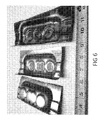
- FIG. 6 is a photograph of a 1550 megapascal workpiece formed in accordance with the present invention.
- FIG. 7 is a photograph of a 1550 megapascal cold formed stamping
- FIG. 8 is a photograph of a 1550 megapascal workpiece used in the automotive industry.
- FIG. 9 is a photograph of another 1550 megapascal cold formed stamping
- FIG. 10 illustrates an angular formed metal stamping, showing a lack of failure
- FIG. 11 is a photograph of yet another cold formed stamping without failure
- FIG. 12 is a photograph of a cold stamped B-pillar part on a laser bed trimming off excess
- FIG. 13 is a photograph of a mock-up of an induction heating coil illustrating 6 legs of parallel, uni-directional current flow with 3 legs on each side of a steel strip;
- FIG. 14 is a photograph of grid etched then room temperature stamped parts of Flash® 1500;
- FIG. 15 is a photomicrograph of enlarged prior austenite grains of Flash® Processed steel.
- FIG. 16 is a depiction of continuous rolling equipment that uses induction heating to spheroidize anneal iron based alloy.
- the Flash® processed steel includes a bi-modal size distribution of bainitic platelets or plates which exhibit highly desirable combinations of strength, ductility and toughness.
- the Flash® processing of the present invention can create almost distortion free flat sheets, bars, plates and straight tubing.
- the microstructure produces a fine grain structure within the bi-modal distribution of microstructures which yields the surprising strength and ductility.
- a graph is shown charting temperature in degrees ° C. versus time in seconds to illustrate the heating and cooling cycle at the inside wall of a tube as it is Flash® Processed. Typical temperature measurements of this inside wall are showing that there is a very low temperature-time history ratio.
- FIG. 2B there is shown a graph of temperature versus time showing the Flash® processing temperature to time history ratio in addition to the conventional steel industry continuous annealing line temperature to time history.
- the temperature to time history ratio for the continuous annealing line is much greater than that ratio for the Flash® processing.
- FIG. 2C illustrates the austenite growth during the Flash® Processing thermal cycle.
- Region I shows prior austenite grains.
- Region II shows austenite growth starting at the grain boundary.
- Region III shows heterogeneous austenite grains in which carbon leveling and full carbide dissolution has not occurred.
- Region IV shows a complex mixture of bainite and martensite within the same prior austenite grains.
- FIG. 3 illustrates an analysis of temperature in degrees centigrade versus the change in temperature also in degrees centigrade.
- This analysis shows intense transformations to austenite daughter phases at between 650 and 550 degrees C. and 460 to 360 degrees C. during cooling.
- This analysis suggests that we have two different transformation conditions leading to very localized microstructural heterogeneity, although experiencing homogeneity on a macro scale.
- the two different transformation temperature ranges are present due to the heterogeneous localized chemistry in the AISI4130 alloy as it is quenched.
- Other iron based alloys will have different temperature ranges but will exhibit the same dual transformation cooling characteristics.
- each transformation is likely a multiplicity of different chemistry transformations occurring at approximately the same location.
- FIG. 4 is a chemical depiction of an individual grain of iron based alloy to create retained austenite.
- the illustration depicts how repeated thermal cycling above and below the lower critical austenite conversion temperature can enrich the grain boundary region of precipitated austenite with carbon and manganese. This occurs because austenite has a higher solubility for both carbon and manganese than does ferrite. Such enrichment will allow precipitated austenite to become stable as retained austenite at room temperature, even after Flash® Processing. Proposed elemental concentrations and volume fractions are provided but are only an example of many possibilities based on bulk chemistry present in the iron based alloy.
- FIG. 5 is a chemical depiction of an individual grain of iron based alloy to create a corrosion resistant iron alloy that could become a Flash® Processed article.
- the illustration depicts how repeated thermal cycling above and below the lower critical austenite conversion temperature can enrich the grain boundary region of precipitate austenite with carbon and potentially manganese. This occurs because austenite has a higher solubility for both carbon and manganese than does ferrite. During this process, grain central regions of ferrite will become depleted of both carbon and manganese. It is well understood by those skilled in the art that carbon and phosphorus prefer to not co-locate. As the carbon moves toward the grain boundary, the phosphorus will move to the grain interior.
- This product with centralized intra granular enrichment of phosphorus is useful in both the pre-Flash® Processed condition and the Flash® Processed condition. Proposed elemental concentrations and volume fractions are provided. It should be noted that manganese is not essential to make corrosion resistant iron alloy and its presence, or lack of, will only affect the volume fraction of retained austenite in the final product. For uses such as architectural sections relying on strength with minimal deflection needed, retained austenite might not be as desirable. However, in articles such as formed automotive components, retained austenite due to the presence of manganese could be beneficial.
- FIG. 6 shows a workpiece, commonly called a “bathtub” automotive part, formed by the methods of the present invention, and as one can note, there are no failures to be observed at the nearly 90° turns in the piece.
- a workpiece commonly called a “bathtub” automotive part
- FIG. 6 shows a workpiece, commonly called a “bathtub” automotive part, formed by the methods of the present invention, and as one can note, there are no failures to be observed at the nearly 90° turns in the piece.
- AISI1020 steel strengths of 1400-1600 MPa, A50 elongation of 6 to 10%, and a Rockwell C hardness of 44 to 48 has been achieved. It is widely accepted since the 1920's that thinner steel sheet will trend toward lower total elongation in tensile testing. However, we did find that Flash® processed AISI1020 at 3 mm thick has a total elongation of 9-10%. As such, one would expect a minimum bend radius of two-T before crack initiation and failure.
- This “bathtub” shaped part was cold stamped, which is a critical method desired by the automotive manufacturers.
- Cold stamping steels with strength of 1500 megapascals is desirable because all the additional steps of “hot stamping” of costly boron steels are alleviated, thereby reducing manufacturing costs by approximately one half.
- the results of these experiments achieved some unexpectedly good results using common plain carbon steels which have very minimal alloy content compared to other advanced high strength steels.
- Plain carbon steel is called out as AISI10##, with the “##” representing the percent weight carbon contained in the steel.
- AISI1020 steel would contain approximately 0.20% wt carbon.
- FIG. 7 shows another example of a 1550 megapascal cold stamped plain carbon steel component manufactured of Flash® Processed sheet with the present invention. Notice again that the pieces do not exhibit failure points, but rather show crisp corners and full forming by cold stamping.
- FIG. 8 illustrates the test results of a Flash® 1550 MPa test on an automotive part called a “Crush Can”.
- the inventor has found that parts made of Flash® at 1550 MPa with only 6% elongation can now be formed like folded over pieces of paper.
- This example shown here in FIG. 8 is one of these automotive “crush cans”.
- Crush cans are located between the vehicle's bumper reinforcement steel and the “frame rails” that extend outward fore and aft from the passenger compartment.
- steel denoted as DP780 dual phase at 780 megapascals
- DP780 is the strongest steel that can be used for crush cans without cracking. This is because DP780 is the strongest steel with historically acceptable ductility that could allow the steel to fold over on itself to a zero-T bend radius while absorbing energy during a crash event, essentially taking on the appearance of an accordion.
- FIG. 13 illustrates a mock-up of an induction heating coil in accordance with the process of the present invention.
- Power from a transformer may be initially connected at 131 .
- Electrical current is evenly distributed over the outside surface of legs 133 , and optional water cooling may be applied at 132 and would run through legs 133 to outlet 134 .
- This particular mock-up of induction coil design illustrates six legs 133 , running in parallel with respect to each other, and perpendicular with respect to steel strip 136 that will be heated as it passes through the induction coil 130 .
- both electrical and water current flow is uni-directional within induction coil 130 , flowing from 132 to 134 , illustrating a novel concept for induction heating.
- induction coil 130 in a unidirectional mode, only transverse surrounding steel strip 136 in the shortest longitudinal length and time in order to achieve high power density in a magnetic field which will be created by the electrical current flowing therethrough.
- Optional cooling water exits at 134 while electrical current converges after running through legs 133 into outlet 134 .
- electrical current leaves induction coil 130 , and returns back to an induction transformer.
- Three legs 133 are shown on each side of steel strip 136 that would be heated by electrical current passing through the three legs 133 on each side of the steel strip 136 .
- FIG. 14 shows cold stamped parts of Flash® processed materials, made from AISI0120 steel at a strength of 1550 MPa. Stamping of flat blanks of steel that were etched with a grid pattern prior to stamping best exemplify the unusual bend-ability of Flash® Processed steel from AISI10##.
- Workpiece 141 shows the top and inverse view of such a piece of approximately 30 cm. long. Workpiece 141 includes the etched square grid marking with its new elongated shape, indicating stretching and bending in multiple directions. Shown at a different angle of workpiece 141 , this same workpiece is designated as 142 , showing its new elongated diamond shape from its previously square grid marking that occurs after forming of the part.
- FIG. 15 is a photomicrograph of enlarged prior austenite grains of Flash® Processed steel exceeding 50 microns in size. These individual grains are divided into segregated regions during quenching by the early transformation at elevated temperatures of low carbon microstructure in chemically lean low carbon regions, such as greater than 99% wt of iron in the alloy. In AISI4130 steel, this early transformation occurs from 650° C. to 550° C. during cooling.
- segregated and refined regions which have the first austenite transformation's phase act as a pseudo grain boundary, which is then transformed at lower temperatures, at cooling from 460° C. down to 360° C., based on their chemistry. While the overall grain size may exceed 50 microns, the segregated regions may be less than 2 microns in a relatively flat configuration, like a series of relatively flat pancakes stacked one on the other, whether truly flat or slightly curled convex or concave shapes. These individual relatively flattened shapes may even constrain the secondary microstructural conversion to a nanometer scale.
- a precursor iron alloy for Flash® processing carbon and manganese content in the iron based alloy will migrate to the grain boundary precipitated austenite during the thermal cycling above and below the lower critical austenization temperature.
- the goal of spheroidize annealing of iron based alloy is to create carbides from any pre-existing pearlitic microstructure areas within the precursor material.
- spheroidizing will soften the iron alloy.
- Spheroidized steel is typically known to be the softest, weakest, most ductile microstructure for a given alloy. It has been discovered that the spheroidization temperature of the steel during the spheroidization annealing process needs to be carefully controlled and monitored to develop the proper microstructure for corrosion resistance, retained austenite, and/or Flash® Processing.
- FIG. 16 is a depiction of a suitable spheroidize annealing line of continuous rolling equipment generally denoted by the numeral 160 that uses induction heating in this example to spheroidize anneal iron based alloys in less than an hour, preferably on the order of minutes.
- an iron alloy sheet 161 enters a multiplicity of rollers 170 shown from the right side of the equipment.
- a first induction heater 162 heats the steel no more than 35° C. above the lower critical austenization temperature of the iron alloy steel being employed, and the austenitizing temperature is dependent upon the iron alloy composition utilized.
- Iron alloy sheet 161 then cools down to at most 35° C. below the lower critical austenization temperature, again dependent upon the alloy utilized.
- Temperature is again optionally maintained in an insulated furnace 163 prior to entering the second induction heater 165 , depicted in this illustration to the left of first induction heater 162 , which again reheats the iron alloy sheet to above the lower critical austenization temperature, as described above.
- the iron alloy sheet 161 may then travel to an optional lower furnace 166 to maintain temperature if desired. The process may be repeated until iron alloy sheet 161 exits. Successive additional induction heating units may be utilized to heat iron alloy sheet 161 to the same temperature or its own discrete temperature, as desired.
- the furnaces 163 and 166 can be maintained at the same temperature or individual heating zones can be established to maintain a different temperature after rolling through each induction heating unit.
- Oven furnace treatments taking up to 72 hours are typical for spheroidize annealing of steel coils to hold the temperature of the entirety of the steel coil just below the lower critical austenite conversion temperature.
- the lengthy thermal cycle is required for the temperature to equalize in the steel coil and allow pearlite to decompose to carbides to a prescribed volume fraction.
- relatively similar but proprietary thermal cycles are commercially used for spheroidization.
- This novel continuous feed rolling equipment being proposed here would feed a coil of iron alloy sheet through a multiplicity of induction heating coils to elevate the sheet's temperature multiple times to decompose its pearlite constituent similar to lengthy spheroidization cycles. Since the sheet of iron alloy is much thinner, using induction heating, for example, to locally heat the iron alloy above the lower critical austenization temperature could be accomplished in seconds instead of hours. When the sheet is heated in the first induction coil above the lower critical temperature, austenite would begin to precipitate at the grain boundary. As pearlite decomposes above the lower austenite temperature, and since austenite has a higher solubility than ferrite for both carbon and manganese, the precipitated grain boundary austenite enriches with both elements.
- each induction coil would be independently controlled to heat the iron alloy to a prescribed temperature above its lower critical austenization temperature while the steel not currently being induction heated would cool below the lower critical austenization temperature.
- the rate of cooling could be controlled through the use of a thermally controlled insulated containment system containing rollers to transfer the steel sheet to prevent too rapid of cooling in ambient air for certain alloys. In other cases, depending on the thickness of the iron alloy and its residual heat content, ambient air cooling works well. While carbon migrates rapidly, it will take between 2 and 60 seconds above the lower austenization temperature to effect the decomposition of the pearlite, precipitation of austenite, and migration of carbon and manganese to the precipitated austenite grain boundary. As detailed above, the example of five cycles above and below the lower critical austenization temperature worked well to attain 30% retained austenite in the final product.
- the method could be applied as well to a rolling strip of metal, such as steel, or other forms of iron based alloy.
- a new method of metal treatment is disclosed which results in transforming a low grade iron based alloy into an advanced high strength steel with extremely rapid heating of the metal followed by rapid quenching of the material without an intentional holding period to chemically homogenize the iron article.
- the resulting iron alloy is preferably a heterogeneous composition of at least two microstructures from the group of martensite, bainite, retained austenite, ferrite and the other microstructures discussed in more detail hereinbelow. Through spheroidize annealing and other prior heat treatments and chemistries, preferred prior microstructures are transformed to effect differing properties in the iron based alloy upon Flash® Processing.
- thermo-mechanical processing techniques require lengthy thermal cycles to obtain a dual phase or complex microstructure typical of advanced high strength steels
- Flash® Processing can do so with a single rapid heating and quenching operation which can take less than 20 seconds from below the lower austenitic temperature to a selected peak temperature and back down to below its martensitic finish temperature.
- Other longer duration methods explained herein can provide desirable metallurgical results provided that the first quenching step to below the bainitic transformation temperature occurs substantially immediately after reaching peak heating temperature.
- Flash® processed complex microstructural material with heterogeneous chemistry bainite and/or martensite interspersed within the same prior austenitic grains.
- Creating a multiplicity of microstructures in a single prior austenite grain can be accomplished through chemical heterogeneity within the grain and the extremely rapid heating/rapid cooling cycle described herein. It is speculated that my heating to an unexpectedly and inordinately high temperature of Flash® Processing enlarges the iron alloy austenite grains to sizes of 5 to 50 microns or more which is counterintuitive to the steel industry's goal of grain refinement.
- Flash® Processed microstructure of plain carbon, or lesser alloy content than required by plain carbon steel specifications can be formed to extreme shapes, provided that the steel is not stretched or elongated past its traditional failure point as part of the forming operation. It is proposed that when describing Flash® Processed iron based alloys, that they be described with the terms strength, elongation, and formability or bendability. These factors identify this newly discovered unexpectedly good result. Flash® processed AISI10## steel thus possesses an unusual bend-ability factor. For example, a conventional “brake press” is used for forming traditional steel in a two dimensional mode to form a linear bending of the sheet about a given radius.
- Flash® Processed AISI10 steel is able to be bent along a non-linear axis of a stamping tool whose bending form could be defined mathematically as a B-spline. Stamping of flat blanks of steel that were etched with a grid pattern prior to stamping best exemplify the unusual bend-ability of Flash® Processed steel from AISI10##. These parts can be seen in FIG. 14 , what was once a square grid pattern has been stretched and compressed to become a rectangle whose length is twice its width.
- Yet another aspect of this invention results in a heterogeneous chemistry microstructure with a desirable volume percentage of retained austenite.
- This heterogeneous microstructure yields a high strength complex multi-phase microstructure suitable for advanced high strength steel applications.
- the precursor steel alloys are homogeneous as austenite, a face centered cubic microstructure.
- the microstructure changes. Some of the prior austenite grains will become ferrite or pearlite when cooled. In some cases, depending on alloying, carbides will precipitate.
- the microstructure When an abundance of carbon, manganese, and/or nickel are present in the localized chemistry at the appropriate weight percent in a portion of a prior austenite grain, the microstructure will become what is called “retained austenite” at room temperature. Carbon in excess of 0.54% wt with 5% wt manganese is one such example, but many other combinations exist. The concentrations of the carbon and manganese can be readily calculated using Continuous Cooling Transformation theory. Those skilled in the art have well developed formulations for determining the percentages necessary of the austenite stabilizing elements such as carbon, manganese, and nickel, which tend to lower the eutectoid temperature of the steel. Retained austenite will lend to ductility and formability of the resulting steel.
- Control of initial microstructure can achieve a more desirable retained austenite novel microstructure that is an excellent precursor for Flash® Processing. It has been discovered that nominal amounts of carbon (0.05% to 0.45% wt) and manganese (0.2% to 5% by weight or more) can be manipulated to concentrate at the prior austenite grain boundary to enrich the region enough to precipitate austenite that is room temperature stable. This is accomplished by cycling the iron alloy below and above its lower critical austenization temperature. When above the lower critical temperature, austenite begins to precipitate at the grain boundary. As pearlite decomposes above the lower austenite temperature, and since austenite has a higher solubility than ferrite for both carbon and manganese, the precipitated grain boundary austenite enriches with both elements.
- the bulk weight percent of manganese present in the alloy chemistry will primarily determine the volume fraction of grain boundary precipitated austenite that stabilizes at room temperature due to its localized enrichment. It should be noted that simply holding the iron alloy above the lower critical austenite conversion temperature tends to create blocky retained austenite. More desired is the present method which creates a network of grain boundary austenite that is interconnected to another, appearing similar to a spider's web.
- this precursor microstructure of austenite, ferrite, pearlite, carbides, and minimally other austenite daughter phases will be converted to an advanced high strength steel.
- the duration of Flash® Processing above the lower austenite conversion temperature is so short, there is minimal time for homogenization to occur, thus the prior heterogeneous microstructure is preserved.
- the grain boundary precipitated austenite will simply reheat and quench to retained austenite.
- Per continuous cooling transformation theory if the elemental percentages were sufficient for precipitated austenite to exist at room temperature prior to Flash® Processing, then the same would be true after rapid Flash® Process cooling.
- the heterogeneous ferrite and pearlite would primarily become a mixture of bainite and martensite after Flash® Processing, based on their localized non-equalized chemistry.
- carbides dissolve during Flash® Processing in regions where manganese and carbon enrichment was not sufficient to previously create precipitated austenite, it has been found that the introduction of this extra carbon from dissolving carbides can combine locally with the existing carbon and manganese to now create room temperature retained austenite.
- Localized creation of retained austenite by introduction of carbon caused by rapid carbide dissolution in a manganese enriched environment just prior to quenching is a novel aspect of this invention.
- Phosphorus is avoided in modern steel making methods to avoid phosphoric embrittlement of prior austenite grain boundaries that occurs during part forming operations in stamping presses and the usage of such parts.
- phosphorus is well documented to reduce the uniaxial elongation significantly by up to 1 ⁇ 3 in many steels. Such a reduction could easily cause the steel part to crack during forming in stamping press operations or roll forming.
- An object such as the ornamental Delhi Pillar is not subjected to the operational stresses of an automotive structural component. However, because the Iron Pillar of Delhi is not under any load, the elevated phosphorus content is not detrimental to the function of the Pillar. Rather, for industrial applications when the steel would be put under load, it would mechanically fail. Flash® processing is ideal for maintaining high phosphorus content in the grain interiors, thereby providing corrosion resistance without exhibiting embrittlement.
- Phosphorus is known to migrate slowly as a solid solution strengthener in a body centered cubic microstructure of ferrite. As such, ferrite can maintain a phosphorus concentration of 0.35% wt at an elevated temperature, but exhibits a near zero concentration at room temperature. Face centered cubic austenite can maintain a phosphorus concentration of only 0.28% wt. It is well known that during typical heat treating operations with lengthy austenization cycles held above the lower austenization temperature, ample time exists for phosphorus to migrate to grain boundaries, and thereby embrittling the steel. Again, for corrosion resistance, the phosphorus needs to stay in the grain interior, not migrate out to the grain boundaries.
- a method is proposed here to yield a corrosion resistant, high phosphorus, iron based alloy which may be used in the condition created by the annealing method described herein or heat treated into an advanced high strength steel by Flash® Processing. Recognizing the relative rapidity of phosphorus migration, any time the iron based alloy spends above its austenization temperatures must be limited to maintain relatively higher concentrations of phosphorus in the prior austenite grain interior. Through methods aforementioned in this application where the iron based alloy is quenched immediately to temperatures below the austenitizing temperature, time spent by the alloy above austenization temperatures can be minimized to prevent phosphorus migration.
- concentrations of phosphorus may be much higher than previously known in the steel industry, from 0.1% to about 2% wt, based on total weight of the alloy. More preferably, the phosphorus content will be from 0.2 to 1.0% wt, such that the phosphorus concentration will create a corrosion resistant steel.
- the corrosion resistance is achieved by a method similar to passivation of stainless steels. An apparent but very thin layer of iron hydrogen phosphate crystallization forms on the steel due to the high phosphorus content.
- the carbon and manganese migrate to the grain boundary precipitated austenite during the thermal cycling above and below the lower critical austenization temperature.
- the phosphorus will migrate to the grain interior since phosphorus prefers to avoid co-location with carbon.
- the grain interior composed primarily of ferrite and undissolved pearlite, will become enriched with phosphorus.
- the bulk iron alloy weight percent of manganese based on the total weight, will determine the volume fraction of precipitated austenite that stabilizes at room temperature.
- the newly exposed iron alloy exhibits a bulk effect because the high phosphorus content is throughout the entire material. Upon scratching the surface, the newly exposed surface develops a thin layer of corrosion resistant iron hydrogen phosphate to match the unscratched areas of the article.
- addition of copper to the steel has been found to increase ductility and machineability while also enhancing the corrosion resisting effects of phosphorus. While an upper limit on copper concentration is not bounded, typically lesser amounts, such as 0.1 wt % to 1.0 wt %, and preferably 0.3% wt copper tends to assist the phosphoric effects. When combining this matrix additive to the method being practiced, an even more superior material results.
- a desirable outcome of spheroidizing the Flash® precursor alloy is to heterogenericize any iron based alloy, such as steel, to a specific grain design. This can be done by heating the alloy or steel up to nearly the lower austenization temperature, or cycling to just above, to create what is known as precipitated austenite. It is well known that austenite precipitates near the perimeter of the grain boundaries leaving ferrite in the center of the steel grain. It is also well known that carbon and manganese will enrich the austenite portion of the steel grain while mostly depleting the central ferrite portion of the steel grain. Additionally, by the nature of the spheroidizing process, carbides will be formed in the areas enriched with carbon, i.e. the austenitic perimeter.
- this desirable precursor alloy microstructure creates a novel martensitic grain central region, optionally phosphorus enriched, surrounded by a partially retained austenite, martensite and/or bainite region at the perimeter of the grain.
- the retained austenite in the perimeter will be caused by a combination of the manganese enrichment in the presence of carbon.
- Another novel aspect of this invention is that some of the retained austenite is actually the prior precipitated austenite from the precursor material creation that was simply Flash® Process heated, and then quenched down in temperature to become what is considered retained austenite.
- CCT Continuous Cooling Transformation
- An example of interrupted cooling during the Flash® Process cycle could occur below the bainite finish temperature of the iron alloy. After the bainite is formed, a localized austenite grain chemistry of 0.01% wt carbon and 5% wt. manganese with a martensitic start temperature of approx 345° C. could exist. The quenching could occur substantially immediately in a molten salt bath which may or may not be agitated. The salt bath should be minimally aqueous/liquefied and be at a temperature that is at least higher than the martensitic start temperature of 345° C. as provided for in this example. At a quench temperature above 345° C., nearly all of the freshly formed austenite will remain untransformed into new austenite daughter phases.
- Various quenching methods may include: first, either directly to room temperature; second, cooling to use CCT to make a prescribed percentage of bainite from the non-transformed austenite; third, cooling to use CCT to make a prescribed percentage of martensite from the non-transformed austenite. Subsequent tempering is optional.
- Flash® invention relates to the induction heating coils that can be used to heat the steel article.
- Induction heating is typically defined by the direction of the induced magnetic flux from the coil. The most common is longitudinal flux induction. The lesser known and used is transverse flux induction.
- the frequency of the induction unit is of extreme importance.
- the induction heating coils will wrap around (or encircle) the part to be heated.
- the heating coil inductor upon leaving one pole of the induction transformer, the heating coil inductor will be constructed to span transverse across the top of the sheet of steel, bridge to the opposite side of the sheet of steel, return across the bottom (or opposite) side, and attach to the other polarity pole of the induction transformer.
- the current flow in the two legs of the induction coil have an opposed directional flow with respect to the article being heated while completing the electrical circuit as current runs through the coil. This opposed current flow may cancel the magnetic field created by the induction coil reducing its ability to heat the steel.
- the penetration depth into the steel part is determined by the frequency.
- Low frequency units such as 1 to 10 kilohertz are typically used to heat sections from 1′′ to 3 ⁇ 8′′ thick respectively.
- Higher frequency units of 100 kHz to 400 kHz are used to heat thinner sections such as 1/16′′ to 1/64′′ thick respectively.
- Cancellation effects occur in the varying thicknesses of heated components such that proper frequency must be selected for the most efficient heating of the component.
- Using too low a frequency in a thinner workpiece will result in cancellation effects that will prevent the part from heating to desired temperature.
- Precise frequency varies per application but is easily determined with the use of commercially available software programs and are well known to those skilled in the art. It is well recognized that for a given power level, measured in kilowatts, higher frequency units can cost double the price of the lower frequency units.
- Transverse flux induction heating methods are well know to heat thinner walled work pieces, especially sheet steels. Lower frequency induction units have the benefit of being lower cost.
- typical transverse flux configurations are limited in effectiveness, power density, and their ability to heat iron based alloys at rates required for the present invention based on their geometric configuration. While longitudinal flux heating coils typically wrap around the work piece and heat from both sides with electrical currents flowing in opposed directions, transverse flux induction heating coils tend to function on a single side of the workpiece.
- transverse flux coil upon leaving one electrical pole of the induction transformer, its copper inductor and its electrical current flow would travel transverse across the sheet, bridge longitudinally up along the length of the strip, move back transverse across the sheet, and then return back down to the point of origin to connect to the other transformer electrical pole.
- two parallel copper inductor legs of the coil heating run transverse across the steel and must be separated along the length of the steel strip to prevent their opposing current flows from cancelling their magnetic fields on the same side of the steel due to them acting with opposing forces on the steel strip.
- a pair of transverse coils can be applied simultaneously to both sides of the steel sheet.
- transverse flux induction heating coils have proven highly effective in heating thin sheet metal rapidly in a short distance and timeframe with a high power density.
- all current flow in the coil's copper legs affecting the steel strip runs in the same direction across the steel strip.
- the electrical circuit created by the copper pole of the inductor of the induction heating coil is divided across multiple legs with the current from all legs flowing in the same direction across the sheet.
- the induction heating coil is constructed from the transformer at one pole.
- a larger cross section leg is initially used, for example, a 3 ⁇ 4′′ square inch copper tube.
- the 3 ⁇ 4′′ square tube branches into multiple 3 ⁇ 8′′ square tubes which run transverse across the steel strip.
- at least one 3 ⁇ 8′′ square tube must run parallel to another 3 ⁇ 8′′ tube on opposite sides of the steel strip, but it is possible for all parallel branches to reside on just one side of the steel strip.
- Additional 3 ⁇ 8′′ square tube inductor legs may be divided from the main 3 ⁇ 4′′ square tube to run on either side of the steel strip. Branching a single 3 ⁇ 4′′ square tube into six 3 ⁇ 8′′ square inductor tubes of which three run parallel on each side of the steel strip works effectively to impart heat to the strip. It is possible by using different geometry tubes for both the initial piece and branches to have many possible combinations of branches running on opposite sides of the steel strip.
- another design could be three copper induction branches on one side of the strip with seven on the other side of the steel strip. Even a scenario with twenty branches on one side and one hundred branches on the other side of the steel strip is possible. While maintaining power density and heating rate, more branches over a greater distance would be typically used in situations where longitudinal feed rates are higher than those slower rates of lesser branches. This is because the time required to Flash® Process must remain minimal to prevent carbon homogenization and carbide dissolution. In all cases, regardless of the number of branches running on both sides of the steel strip, the branches join together again once past the steel strip and again mechanically connect to ultimately attach to the other electrical pole of the transformer.
- the branches By having all current flow in the same direction along the tubular branches of the induction heating coil, the branches can be placed in close proximity to each other without the negating effects of cancellation occurring that are typical to a current flow system that has current running in opposed directions.
- Single direction current flow through the copper tubing effecting the steel strip is novel compared to the opposed current flow across the strip of typical traditional transverse flux induction heating.
- An additional method is to have a ceramic sleeve inserted inside the induction coil that has an opening that is slightly wider and thicker than the steel strip being austenitized.
- an opening thickness that is only approximately 0.1 mm to 0.2 mm thicker than the steel strip being austenized, there would be very limited space for the steel to ripple/wave.
- the entire induction coil could be ceramic coated with a spacer the thickness of the steel strip, plus a minimal running clearance, held in place as a mold when the ceramic coating hardens. Upon hardening of the coating, the steel strip could be removed leaving a minimal clearance gap for the steel strip to be Flash® austenized to pass through.
- chilling rollers well known to those in the steel industry.
- the rollers could be constructed of copper and optionally water cooled through their center or by water spray to the exterior.
- the water cooling could be used to remove the heat from austenized iron based alloy and induce the transformation to austenite daughter phases.
- water spray could be applied to the exiting faces of the iron sheet as it leaves the copper rollers to enact the transformation to austenite daughter phases.
- the carbon stabilizes the retained austenite by the rapid partial dissolution of carbides into the manganese enriched perimeter region during the rapid heating cycle of the Flash® Processing.
- All other known methods of creating retained austenite rely on either existing high carbon enrichment or migration of carbon during a partitioning process after the initial quenching has occurred. None of those conditions appear to be requisite when following the present invention. Therefore, a new microstructure is formed with a very desirable result without following old prior art compositions or methods.
- the individual grains of the newly formed steel will possess novel properties.
- the optional phosphorus will cause a passivation layer to be formed that will be corrosion resistant.
- the retained austenite regions will be of value as a highly ductile strain hardening component.
- the combination of bainite and martensite will lead to what has been called “maximum strength steel” when the bainite to martensite ratio is 20-25% by volume.
- the presence of undissolved or partially dissolved carbides will be of value as a hard abrasion resistant component and also as a fracture interrupter to limit failure modes.
- the present invention finds applicability in the metal treatment industry and finds particular utility in steel treatment applications for the processing and manufacture of high strength steels in high volume processing.
Landscapes
- Chemical & Material Sciences (AREA)
- Engineering & Computer Science (AREA)
- Mechanical Engineering (AREA)
- Materials Engineering (AREA)
- Metallurgy (AREA)
- Organic Chemistry (AREA)
- Physics & Mathematics (AREA)
- Thermal Sciences (AREA)
- Crystallography & Structural Chemistry (AREA)
- Heat Treatment Of Articles (AREA)
- Heat Treatment Of Steel (AREA)
Priority Applications (1)
| Application Number | Priority Date | Filing Date | Title |
|---|---|---|---|
| US15/319,710 US20170145528A1 (en) | 2014-06-17 | 2015-06-07 | High Strength Iron-Based Alloys, Processes for Making Same, and Articles Resulting Therefrom |
Applications Claiming Priority (5)
| Application Number | Priority Date | Filing Date | Title |
|---|---|---|---|
| US201462013396P | 2014-06-17 | 2014-06-17 | |
| US201462093731P | 2014-12-18 | 2014-12-18 | |
| US201562100373P | 2015-01-06 | 2015-01-06 | |
| US15/319,710 US20170145528A1 (en) | 2014-06-17 | 2015-06-07 | High Strength Iron-Based Alloys, Processes for Making Same, and Articles Resulting Therefrom |
| PCT/US2015/036313 WO2015195851A1 (en) | 2014-06-17 | 2015-06-17 | High strength iron-based alloys, processes for making same, and articles resulting therefrom |
Publications (1)
| Publication Number | Publication Date |
|---|---|
| US20170145528A1 true US20170145528A1 (en) | 2017-05-25 |
Family
ID=54936087
Family Applications (1)
| Application Number | Title | Priority Date | Filing Date |
|---|---|---|---|
| US15/319,710 Abandoned US20170145528A1 (en) | 2014-06-17 | 2015-06-07 | High Strength Iron-Based Alloys, Processes for Making Same, and Articles Resulting Therefrom |
Country Status (8)
| Country | Link |
|---|---|
| US (1) | US20170145528A1 (enExample) |
| EP (1) | EP3158100A4 (enExample) |
| JP (2) | JP2017524813A (enExample) |
| CN (2) | CN106414787B (enExample) |
| AU (1) | AU2015277142A1 (enExample) |
| CA (1) | CA2952255C (enExample) |
| MX (2) | MX2016016888A (enExample) |
| WO (1) | WO2015195851A1 (enExample) |
Cited By (3)
| Publication number | Priority date | Publication date | Assignee | Title |
|---|---|---|---|---|
| US20180023156A1 (en) * | 2016-07-20 | 2018-01-25 | Hyundai America Technical Center, Inc | Lightweight door beam, composition thereof and method of manufacturing the same |
| US20180171423A1 (en) * | 2016-12-15 | 2018-06-21 | Hyundai Motor Company | Three-Dimensional Cooling Type Hot-Stamping Method and System and Vehicle Structural Member Manufactured by the Same |
| WO2019079763A1 (en) * | 2017-10-19 | 2019-04-25 | Cola Gary M Jr | HIGH STRENGTH STEELS, METHODS OF MANUFACTURE THEREOF AND ARTICLES RESULTING FROM THE SAME |
Citations (5)
| Publication number | Priority date | Publication date | Assignee | Title |
|---|---|---|---|---|
| US6395108B2 (en) * | 1998-07-08 | 2002-05-28 | Recherche Et Developpement Du Groupe Cockerill Sambre | Flat product, such as sheet, made of steel having a high yield strength and exhibiting good ductility and process for manufacturing this product |
| US20100132854A1 (en) * | 2006-10-03 | 2010-06-03 | Cola Jr Gary M | Microtreatment of Iron-Based Alloy, Apparatus and Method Therefor, and Articles Resulting Therefrom |
| US20130048151A1 (en) * | 2010-02-26 | 2013-02-28 | Jfe Steel Corporation | Ultra high strength cold rolled steel sheet having excellent bendability |
| US20130186527A1 (en) * | 2012-01-20 | 2013-07-25 | GM Global Technology Operations LLC | Heat treatment for producing steel sheet with high strength and ductility |
| US20170130295A1 (en) * | 2014-06-16 | 2017-05-11 | Kabushiki Kaisha Kobe Seiko Sho (Kobe Steel, Ltd.) | Steel for mechanical structure for cold working, and method for producing same |
Family Cites Families (16)
| Publication number | Priority date | Publication date | Assignee | Title |
|---|---|---|---|---|
| JPS63115654A (ja) * | 1986-11-05 | 1988-05-20 | Mitsubishi Heavy Ind Ltd | 金属薄板鋳造方法及び装置 |
| JP2001011575A (ja) * | 1999-06-30 | 2001-01-16 | Nippon Steel Corp | 冷間加工性に優れた機械構造用棒鋼・鋼線及びその製造方法 |
| JP2002363650A (ja) * | 2001-06-07 | 2002-12-18 | Kobe Steel Ltd | シーム溶接性に優れた超高強度冷延鋼板の製造方法 |
| CN100432244C (zh) * | 2007-04-02 | 2008-11-12 | 马鞍山钢铁股份有限公司 | 中碳钢形变诱导铁素体超量析出生产方法 |
| US20100163140A1 (en) * | 2008-06-16 | 2010-07-01 | Cola Jr Gary M | Microtreatment of Iron-Based Alloy, Apparatus and Method Therefor, and Microstructure Resulting Therefrom |
| CN101845599B (zh) * | 2009-03-24 | 2012-05-30 | 宝山钢铁股份有限公司 | 一种耐候钢及其制造方法 |
| JP5493986B2 (ja) * | 2009-04-27 | 2014-05-14 | Jfeスチール株式会社 | 加工性に優れた高強度鋼板および高強度溶融亜鉛めっき鋼板並びにそれらの製造方法 |
| FR2951198B1 (fr) * | 2009-10-12 | 2013-05-10 | Snecma | Traitements thermiques d'aciers martensitiques inoxydables apres refusion sous laitier |
| JP5466576B2 (ja) * | 2010-05-24 | 2014-04-09 | 株式会社神戸製鋼所 | 曲げ加工性に優れた高強度冷延鋼板 |
| JP5740908B2 (ja) * | 2010-10-20 | 2015-07-01 | 新日鐵住金株式会社 | 冷間鍛造後の急速加熱焼入れ性に優れた中炭素鋼板の焼入れ方法 |
| JP5856002B2 (ja) * | 2011-05-12 | 2016-02-09 | Jfeスチール株式会社 | 衝突エネルギー吸収能に優れた自動車用衝突エネルギー吸収部材およびその製造方法 |
| CN102828119A (zh) * | 2011-06-14 | 2012-12-19 | 鞍钢股份有限公司 | 高弯曲型980MPa级冷轧双相钢及其制备工艺 |
| JP5825185B2 (ja) * | 2012-04-18 | 2015-12-02 | 新日鐵住金株式会社 | 冷延鋼板およびその製造方法 |
| CN104641006B (zh) * | 2012-05-25 | 2018-02-13 | 加里·M·科拉 | 含碳化物的铁基合金的微处理和微结构 |
| JP5821794B2 (ja) * | 2012-07-18 | 2015-11-24 | 新日鐵住金株式会社 | 焼入れ鋼材およびその製造方法ならびに焼入れ用鋼材 |
| JP5906154B2 (ja) * | 2012-07-20 | 2016-04-20 | 株式会社神戸製鋼所 | 耐遅れ破壊性に優れた高強度鋼板およびその製造方法 |
-
2015
- 2015-06-07 US US15/319,710 patent/US20170145528A1/en not_active Abandoned
- 2015-06-17 EP EP15809902.8A patent/EP3158100A4/en not_active Withdrawn
- 2015-06-17 CN CN201580032939.9A patent/CN106414787B/zh active Active
- 2015-06-17 JP JP2016573965A patent/JP2017524813A/ja active Pending
- 2015-06-17 AU AU2015277142A patent/AU2015277142A1/en not_active Abandoned
- 2015-06-17 CN CN201910163334.3A patent/CN110042313B/zh active Active
- 2015-06-17 CA CA2952255A patent/CA2952255C/en active Active
- 2015-06-17 WO PCT/US2015/036313 patent/WO2015195851A1/en not_active Ceased
- 2015-06-17 MX MX2016016888A patent/MX2016016888A/es unknown
-
2016
- 2016-12-16 MX MX2023007656A patent/MX2023007656A/es unknown
-
2020
- 2020-12-01 JP JP2020199811A patent/JP2021046611A/ja active Pending
Patent Citations (5)
| Publication number | Priority date | Publication date | Assignee | Title |
|---|---|---|---|---|
| US6395108B2 (en) * | 1998-07-08 | 2002-05-28 | Recherche Et Developpement Du Groupe Cockerill Sambre | Flat product, such as sheet, made of steel having a high yield strength and exhibiting good ductility and process for manufacturing this product |
| US20100132854A1 (en) * | 2006-10-03 | 2010-06-03 | Cola Jr Gary M | Microtreatment of Iron-Based Alloy, Apparatus and Method Therefor, and Articles Resulting Therefrom |
| US20130048151A1 (en) * | 2010-02-26 | 2013-02-28 | Jfe Steel Corporation | Ultra high strength cold rolled steel sheet having excellent bendability |
| US20130186527A1 (en) * | 2012-01-20 | 2013-07-25 | GM Global Technology Operations LLC | Heat treatment for producing steel sheet with high strength and ductility |
| US20170130295A1 (en) * | 2014-06-16 | 2017-05-11 | Kabushiki Kaisha Kobe Seiko Sho (Kobe Steel, Ltd.) | Steel for mechanical structure for cold working, and method for producing same |
Non-Patent Citations (1)
| Title |
|---|
| Chen previously cited, , H.C., Era, H. & Shimizu, M. MTA (1989) 20 437. * |
Cited By (6)
| Publication number | Priority date | Publication date | Assignee | Title |
|---|---|---|---|---|
| US20180023156A1 (en) * | 2016-07-20 | 2018-01-25 | Hyundai America Technical Center, Inc | Lightweight door beam, composition thereof and method of manufacturing the same |
| US10961599B2 (en) * | 2016-07-20 | 2021-03-30 | Hyundai Motor Company | Lightweight door beam, composition thereof and method of manufacturing the same |
| US11702715B2 (en) | 2016-07-20 | 2023-07-18 | Hyundai Motor Company | Lightweight door beam, composition thereof and method of manufacturing the same |
| US20180171423A1 (en) * | 2016-12-15 | 2018-06-21 | Hyundai Motor Company | Three-Dimensional Cooling Type Hot-Stamping Method and System and Vehicle Structural Member Manufactured by the Same |
| US11078551B2 (en) * | 2016-12-15 | 2021-08-03 | Hyundai Motor Company | Three-dimensional cooling type hot-stamping method and system and vehicle structural member manufactured by the same |
| WO2019079763A1 (en) * | 2017-10-19 | 2019-04-25 | Cola Gary M Jr | HIGH STRENGTH STEELS, METHODS OF MANUFACTURE THEREOF AND ARTICLES RESULTING FROM THE SAME |
Also Published As
| Publication number | Publication date |
|---|---|
| EP3158100A4 (en) | 2018-02-28 |
| CN106414787B (zh) | 2020-07-14 |
| MX2023007656A (es) | 2023-07-07 |
| EP3158100A1 (en) | 2017-04-26 |
| CN110042313B (zh) | 2021-11-30 |
| CN110042313A (zh) | 2019-07-23 |
| JP2021046611A (ja) | 2021-03-25 |
| CN106414787A (zh) | 2017-02-15 |
| CA2952255C (en) | 2023-07-25 |
| CA2952255A1 (en) | 2015-12-23 |
| MX2016016888A (es) | 2017-07-27 |
| WO2015195851A1 (en) | 2015-12-23 |
| JP2017524813A (ja) | 2017-08-31 |
| AU2015277142A1 (en) | 2017-02-02 |
Similar Documents
| Publication | Publication Date | Title |
|---|---|---|
| US8518195B2 (en) | Heat treatment for producing steel sheet with high strength and ductility | |
| JP6843612B2 (ja) | 良好な延性を示す高強度鋼およびインライン熱処理下流の溶融亜鉛浴による製造方法 | |
| ZA201007964B (en) | Manufacturing method for very high-strength cold-rolled dual-phase steel sheets and sheets so produced | |
| JP2016503458A (ja) | 高成形性超高強度冷間圧延鋼板及びその製造方法 | |
| CN105648317A (zh) | 一种高强度高塑性中锰q&p钢冷轧退火板及其制备工艺 | |
| KR20170026394A (ko) | 향상된 강도 및 성형성을 갖는 고강도 강 시트의 제조 방법 및 획득된 시트 | |
| CA3076934C (en) | Press hardened steel with tailored properties after novel thermal treatment | |
| CN110055465B (zh) | 一种中锰超高强度钢及其制备方法 | |
| FI3853387T3 (fi) | Kylmävalssattu ja pinnoitettu teräslevy ja menetelmä sen valmistamiseksi | |
| EP2855714B1 (en) | Microtreatment and microstructure of carbide containing iron-based alloy | |
| CA2952255C (en) | High strength iron-based alloys, processes for making same, and articles resulting therefrom | |
| US20100163140A1 (en) | Microtreatment of Iron-Based Alloy, Apparatus and Method Therefor, and Microstructure Resulting Therefrom | |
| JP2017524813A5 (enExample) | ||
| JP4983082B2 (ja) | 高強度鋼材及びその製造方法 | |
| JP6068570B2 (ja) | 高強度鋼板の焼きなましプロセス | |
| US20170335418A1 (en) | High strength iron-based alloys, processes for making same, and articles resulting therefrom | |
| JPH03180426A (ja) | 穴拡げ性の優れた高強度熱延鋼板の製造方法 | |
| JP7129974B2 (ja) | 鋼管のインライン製造方法 | |
| JPS6047886B2 (ja) | 連続焼鈍による加工用高強度薄鋼板の製造法 | |
| JPH01168813A (ja) | プレス加工性の優れた高強度熱延薄鋼板の製造方法 | |
| JPH0860305A (ja) | 疲労特性に優れた耐熱軟化性を有する加工用熱延高強度鋼板およびその製造方法 | |
| JPH04128319A (ja) | 低降伏比高強度冷延鋼板の製造方法 |
Legal Events
| Date | Code | Title | Description |
|---|---|---|---|
| STPP | Information on status: patent application and granting procedure in general |
Free format text: NON FINAL ACTION MAILED |
|
| STPP | Information on status: patent application and granting procedure in general |
Free format text: RESPONSE TO NON-FINAL OFFICE ACTION ENTERED AND FORWARDED TO EXAMINER |
|
| STPP | Information on status: patent application and granting procedure in general |
Free format text: FINAL REJECTION MAILED |
|
| STPP | Information on status: patent application and granting procedure in general |
Free format text: DOCKETED NEW CASE - READY FOR EXAMINATION |
|
| STPP | Information on status: patent application and granting procedure in general |
Free format text: NON FINAL ACTION MAILED |
|
| STCB | Information on status: application discontinuation |
Free format text: ABANDONED -- FAILURE TO RESPOND TO AN OFFICE ACTION |