US2016237A - Car coupler mechanism - Google Patents
Car coupler mechanism Download PDFInfo
- Publication number
- US2016237A US2016237A US494415A US49441530A US2016237A US 2016237 A US2016237 A US 2016237A US 494415 A US494415 A US 494415A US 49441530 A US49441530 A US 49441530A US 2016237 A US2016237 A US 2016237A
- Authority
- US
- United States
- Prior art keywords
- yoke
- follower
- key
- draft
- housing
- Prior art date
- Legal status (The legal status is an assumption and is not a legal conclusion. Google has not performed a legal analysis and makes no representation as to the accuracy of the status listed.)
- Expired - Lifetime
Links
- 230000007246 mechanism Effects 0.000 title description 9
- 238000010276 construction Methods 0.000 description 3
- 230000008901 benefit Effects 0.000 description 2
- 230000006835 compression Effects 0.000 description 2
- 238000007906 compression Methods 0.000 description 2
- 238000005266 casting Methods 0.000 description 1
- 230000008878 coupling Effects 0.000 description 1
- 238000010168 coupling process Methods 0.000 description 1
- 238000005859 coupling reaction Methods 0.000 description 1
- 238000005058 metal casting Methods 0.000 description 1
Images

Classifications
-
- B—PERFORMING OPERATIONS; TRANSPORTING
- B61—RAILWAYS
- B61G—COUPLINGS; DRAUGHT AND BUFFING APPLIANCES
- B61G9/00—Draw-gear
- B61G9/20—Details; Accessories
- B61G9/24—Linkages between draw-bar and framework
Definitions
- This invention relates to improvements in car coupler mechanism having draft gears of the double-acting type.
- the selective travel or double-acting gear is 5 a type that has recently come on the market, and
- the primary object of the present invention is to rovide a novel coupling mechanism in which the yoke and housing of the double-acting draft gear are formed of a single piece metal casting.
- Another object is to provide such a mechanism in which the front draft lugs are omitted.
- a still further object is to furnish a coupler mechanism of the'double-acting type, which is of stronger, lighter and more compact construction than those heretofore known.
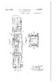
- Fig. l is a horizontal sectional View partly in top plan, of a coupler mechanism equipped with our improvements.
- Fig. 2 is a vertical sectional view of the same, partly in elevation.
- Fig. 3 is a transverse sectional view on the line 3-3 of Fig. 2, and with the rear key omitted.
- I designates the improved yoke, which is tubular for the greatest portion of its length, as shown at 2, to form the draft gear housing.
- the front follower is shown at 5, and the rear follower is indicated at 6.
- These followers, as well as the draft gear and yoke are positioned between the side sills 1, and the latter are tied together by a center brace 9 which is integral with the rear draft lugs 8, against which the follower 6 bears.
- a striker casting I0 joins the front ends of the sills and receives coupler shank Il which has a slot l2 through which the key 4 extends.
- the key also extends through slots i3 in the sides of the yoke and slots ifi in the sills, and it will be noted that the slot l2 is of about the same width v as the key, while the slots I3 are of greater length ⁇ 5 than the key and bear against the latter only at their front ends. The slots it are considerably wider than the slots i 3, and the key does not bear against the ends of the slots it.
- Draft lugs or cheek plates it are firmly united with the outer sides of the sills, and have slots lc2L of about the same width as the slots l5.
- the key 3 bears at its front edge against the front ends l5 cf the slots Ilia.
- the springs or front yielding elements are shoWn at i8, and the rear yielding elements at Illia.
- the front yielding elements bears at one end upon the front follower 5 and at its rear end 20 upon a second follower i9 abutting the key 3.'
- the rear yielding element H80. bears at its rear end upon the follower 5, while its front end abuts a second follower ld.
- the followers I9, l Sla abut the key and reciprocate with the latter relative 25 to the yoke.
- the coupler shank Il exerts a pulling force on the yoke and draft gear housing 2 by means of the horizontal key t.
- the yoke and follower E5 compress the rear yielding element d8a against the follower isa, which is 30 held by the key 3, and through the latter, transmits the draft forces to the center sill 1.
- both the front and rear yielding elements are compressed against the rear follower 6 which transmits the bufling forces through the 35 4 draft lugs 9 to the center sills.
- the key 3 and followers l 9 and E9e move rearwardly a distance equal to the compression of the rear yielding element.
- the invention has the advantage of reducing the weight of the yoke and gear assembly, due to the fact that the yoke straps, form a part of the gear housing. Furthermore, a construction of this character can occupy a smaller space than if the housing and yoke were separate elements.
- draft gear housing means a casing in which is assembled the usual springs Y and friction elements which make up a draft gear. It is a container for these parts, and essential to the operation as a draft gear.
- draft sills In combination, draft sills, a unitary yokeand draft gear housing arranged between Vsaid draft sillsA and adapted to move forwardly and rearwardly in unison, stationary Vstops at the rear end of the combined yoke and housing, front and rear followers mounted for reciprocation in the combined yoke and housing longitudinally of the latter, rear yielding elements in the combined housing and yoke for normally holding the rear follower in contact with said stops, front yielding elements for normally holding the front follower in contact with portions of the combinedV yoke and housing, means separating the front yielding elements from the rear yielding elements and operatively connected to said sills for limiting forward movement of the rear yielding elements during pull while said rear yielding elements are compressed, and for compressing said rear yielding elements during buff while the reark stops restrict rearward ⁇ movement of the rear follower, a coupler shank, a second horizontal key connecting said shank to the forward end.
- said second key being movable with the shank relatively to the sills during both buff and draft and relatively to the yoke and dra-ft gear housing during buff only, said shank being engageable with the front foliower and adapted during bui to move the front follower rearwardly and thereby cause the front yielding elements to be compressed, and the front yielding elements to in turn shift said means rearwardly.
Landscapes
- Engineering & Computer Science (AREA)
- Mechanical Engineering (AREA)
- Lock And Its Accessories (AREA)
Description
m., L, ma
www
JOHNSON ET AL CAR COUPLER MECHANI SM Filed Nov. 8, 195o 2 Sheets-Sheet l a BY dY--J `2 s'heets-sheet 2 INVENTORS,
#K1-gf@ ATTORNYS.
j y :la
ch L l35.
G.-T. JOHNSON ET AL CAR COUPLER MECHANISM Filed NOV. 8, 1930 Patented Oct. 1, 1935 UNHTED STATES PATENT OFFICE CAR COUPLER MECHANISM Application November 8, 1930, Serial No.494,415
1 Claim.
This invention relates to improvements in car coupler mechanism having draft gears of the double-acting type.
The selective travel or double-acting gear is 5 a type that has recently come on the market, and
it functions somewhat differently from the ordinary draft gear. We have devised an improved mechanism of this kind.
In freight car service, the greatest forces on the couplers are the bufng forces, and a doublecting draffJ gear has practically twice the capacity in buff as it has in pull.
The primary object of the present invention is to rovide a novel coupling mechanism in which the yoke and housing of the double-acting draft gear are formed of a single piece metal casting.
Another object is to provide such a mechanism in which the front draft lugs are omitted.
A still further object is to furnish a coupler mechanism of the'double-acting type, which is of stronger, lighter and more compact construction than those heretofore known.
With the foregoing objects outlined and with other objects in view which will appear as the description proceeds, the invention consists in the novel features hereinafter described in detail, illustrated in the accompanying drawings, and more particularly pointed out in the appended claim.
In the drawings,
Fig. l is a horizontal sectional View partly in top plan, of a coupler mechanism equipped with our improvements.
Fig. 2 is a vertical sectional view of the same, partly in elevation.
Fig. 3 is a transverse sectional view on the line 3-3 of Fig. 2, and with the rear key omitted.
Referring to the drawings, I designates the improved yoke, which is tubular for the greatest portion of its length, as shown at 2, to form the draft gear housing.
3 designates the rear key which is horizontally arranged and passes through the side sills, yoke and draft gear.
4 designates the front coupler key within is also horizontally arranged.
The front follower is shown at 5, and the rear follower is indicated at 6. These followers, as well as the draft gear and yoke are positioned between the side sills 1, and the latter are tied together by a center brace 9 which is integral with the rear draft lugs 8, against which the follower 6 bears. v
A striker casting I0 joins the front ends of the sills and receives coupler shank Il which has a slot l2 through which the key 4 extends. The key also extends through slots i3 in the sides of the yoke and slots ifi in the sills, and it will be noted that the slot l2 is of about the same width v as the key, while the slots I3 are of greater length `5 than the key and bear against the latter only at their front ends. The slots it are considerably wider than the slots i 3, and the key does not bear against the ends of the slots it. l
Slots are formed in the sides of the draft gear 10 housing, as shown at l5.
Draft lugs or cheek plates it are firmly united with the outer sides of the sills, and have slots lc2L of about the same width as the slots l5. The key 3 bears at its front edge against the front ends l5 cf the slots Ilia.
The springs or front yielding elements are shoWn at i8, and the rear yielding elements at Illia. The front yielding elements bears at one end upon the front follower 5 and at its rear end 20 upon a second follower i9 abutting the key 3.' The rear yielding element H80. bears at its rear end upon the follower 5, while its front end abuts a second follower ld. The followers I9, l Sla abut the key and reciprocate with the latter relative 25 to the yoke. During pull, the coupler shank Il exerts a pulling force on the yoke and draft gear housing 2 by means of the horizontal key t. The yoke and follower E5 compress the rear yielding element d8a against the follower isa, which is 30 held by the key 3, and through the latter, transmits the draft forces to the center sill 1. During buff, both the front and rear yielding elements are compressed against the rear follower 6 which transmits the bufling forces through the 35 4 draft lugs 9 to the center sills. The key 3 and followers l 9 and E9e move rearwardly a distance equal to the compression of the rear yielding element.
While it is not our intention to limit ourselves 40 to any one type of yielding elements, a simple type of yielding elements or draft gear which can be used with the housing, is illustrated in the drawings. Many other types of yielding elements could be used with the housing, and also 45 by slight changes in contour of the inside surfa-ce of the housing, other types of draft gear can be used.
In operation, when a pull is exerted by the coupler shank il, the key 4 will cause the yoke l 50 to move forwardly, and this will result in forward movement of the follower plate il by the rear end of the yoke, and the rear portion of the draft gear will be compressed against the key 3, which will in turn bear against the lugs I6 and trans- 55 mit the pulling movement to the car sills 1. Y During such movement, the follower plate 6 and yoke will travel forward a distance equal to the compression of the rear portion of the draft gear.
In buff, the coupler shank H bears against the follower 5, as shown at il, and while the follower is moved the distance indicated at B, the yoke will be caused to move rearwardly and the follower 5, through the instrumentality of the front yielding element, will force the key 3 to compress the draft gear against the follower plate "5, so that the gear will be further compressed equal to the distance A, and the rear end of the yoke will come into the dotted line position shown at C, when the gear is fully compressed.
The invention has the advantage of reducing the weight of the yoke and gear assembly, due to the fact that the yoke straps, form a part of the gear housing. Furthermore, a construction of this character can occupy a smaller space than if the housing and yoke were separate elements.
In the claim, draft gear housing means a casing in which is assembled the usual springs Y and friction elements which make up a draft gear. It is a container for these parts, and essential to the operation as a draft gear.
From the foregoing it is ,believed that the construction, operation and advantages of the invention may be readily understood, and it is manifest that changes may be made in the details disclosed, without departing from the spirit of the invention, as described in the claim.
What is claimed and desired to be secured by Letters Patent is:
In combination, draft sills, a unitary yokeand draft gear housing arranged between Vsaid draft sillsA and adapted to move forwardly and rearwardly in unison, stationary Vstops at the rear end of the combined yoke and housing, front and rear followers mounted for reciprocation in the combined yoke and housing longitudinally of the latter, rear yielding elements in the combined housing and yoke for normally holding the rear follower in contact with said stops, front yielding elements for normally holding the front follower in contact with portions of the combinedV yoke and housing, means separating the front yielding elements from the rear yielding elements and operatively connected to said sills for limiting forward movement of the rear yielding elements during pull while said rear yielding elements are compressed, and for compressing said rear yielding elements during buff while the reark stops restrict rearward` movement of the rear follower, a coupler shank, a second horizontal key connecting said shank to the forward end. of the unitary yoke and draft gear housing and sills, said second key being movable with the shank relatively to the sills during both buff and draft and relatively to the yoke and dra-ft gear housing during buff only, said shank being engageable with the front foliower and adapted during bui to move the front follower rearwardly and thereby cause the front yielding elements to be compressed, and the front yielding elements to in turn shift said means rearwardly.
' GEORGE T. JOHNSON.
HARRY H. WOLFE.
Priority Applications (1)
| Application Number | Priority Date | Filing Date | Title |
|---|---|---|---|
| US494415A US2016237A (en) | 1930-11-08 | 1930-11-08 | Car coupler mechanism |
Applications Claiming Priority (1)
| Application Number | Priority Date | Filing Date | Title |
|---|---|---|---|
| US494415A US2016237A (en) | 1930-11-08 | 1930-11-08 | Car coupler mechanism |
Publications (1)
| Publication Number | Publication Date |
|---|---|
| US2016237A true US2016237A (en) | 1935-10-01 |
Family
ID=23964379
Family Applications (1)
| Application Number | Title | Priority Date | Filing Date |
|---|---|---|---|
| US494415A Expired - Lifetime US2016237A (en) | 1930-11-08 | 1930-11-08 | Car coupler mechanism |
Country Status (1)
| Country | Link |
|---|---|
| US (1) | US2016237A (en) |
Cited By (1)
| Publication number | Priority date | Publication date | Assignee | Title |
|---|---|---|---|---|
| US3193111A (en) * | 1962-07-09 | 1965-07-06 | Standard Car Truck Co | Draft gear rigging for railroad cars |
-
1930
- 1930-11-08 US US494415A patent/US2016237A/en not_active Expired - Lifetime
Cited By (1)
| Publication number | Priority date | Publication date | Assignee | Title |
|---|---|---|---|---|
| US3193111A (en) * | 1962-07-09 | 1965-07-06 | Standard Car Truck Co | Draft gear rigging for railroad cars |
Similar Documents
| Publication | Publication Date | Title |
|---|---|---|
| US2016237A (en) | Car coupler mechanism | |
| US1199167A (en) | Draft-gear. | |
| US1765875A (en) | Friction gear | |
| US1629307A (en) | Draft gear | |
| US1947316A (en) | Draft rigging | |
| US1273908A (en) | Draft-rigging for cars. | |
| US1192100A (en) | Spring draft-gear. | |
| US1763974A (en) | Railway draft rigging | |
| US2053939A (en) | Draft rigging | |
| US1073163A (en) | Draft-rigging for railway-cars. | |
| US1648297A (en) | Draft gear | |
| US684245A (en) | Draw-bar draft-rigging for car-couplings. | |
| US1357776A (en) | Tandem draft-rigging for railway-cars | |
| US754676A (en) | Tandem fricton spring draft-rigging for railway-cars. | |
| US1130999A (en) | Railway draft-rigging. | |
| US1492779A (en) | Friction draft gear | |
| US734012A (en) | Tandem-spring friction draft-rigging for railway-cars. | |
| US1123853A (en) | Draft-gear. | |
| US1253088A (en) | Spring draft-rigging. | |
| US1196917A (en) | Transom draft-gear. | |
| US1134576A (en) | Draft-rigging. | |
| US1192154A (en) | Railway-car draft-rigging. | |
| US734011A (en) | Friction draft-rigging for railway-cars. | |
| US1174987A (en) | Draft-rigging for railway-cars. | |
| US1142832A (en) | Buffing mechanism for railroad-cars. |