US20140091663A1 - Permanent-magnet type rotating electrical machine - Google Patents
Permanent-magnet type rotating electrical machine Download PDFInfo
- Publication number
- US20140091663A1 US20140091663A1 US14/118,123 US201114118123A US2014091663A1 US 20140091663 A1 US20140091663 A1 US 20140091663A1 US 201114118123 A US201114118123 A US 201114118123A US 2014091663 A1 US2014091663 A1 US 2014091663A1
- Authority
- US
- United States
- Prior art keywords
- permanent
- flux control
- magnet
- rotor core
- rotor
- Prior art date
- Legal status (The legal status is an assumption and is not a legal conclusion. Google has not performed a legal analysis and makes no representation as to the accuracy of the status listed.)
- Abandoned
Links
Images


Classifications
-
- H—ELECTRICITY
- H02—GENERATION; CONVERSION OR DISTRIBUTION OF ELECTRIC POWER
- H02K—DYNAMO-ELECTRIC MACHINES
- H02K1/00—Details of the magnetic circuit
- H02K1/06—Details of the magnetic circuit characterised by the shape, form or construction
- H02K1/22—Rotating parts of the magnetic circuit
- H02K1/27—Rotor cores with permanent magnets
- H02K1/2706—Inner rotors
- H02K1/272—Inner rotors the magnetisation axis of the magnets being perpendicular to the rotor axis
- H02K1/274—Inner rotors the magnetisation axis of the magnets being perpendicular to the rotor axis the rotor consisting of two or more circumferentially positioned magnets
- H02K1/2753—Inner rotors the magnetisation axis of the magnets being perpendicular to the rotor axis the rotor consisting of two or more circumferentially positioned magnets the rotor consisting of magnets or groups of magnets arranged with alternating polarity
- H02K1/276—Magnets embedded in the magnetic core, e.g. interior permanent magnets [IPM]
- H02K1/2766—Magnets embedded in the magnetic core, e.g. interior permanent magnets [IPM] having a flux concentration effect
-
- H—ELECTRICITY
- H02—GENERATION; CONVERSION OR DISTRIBUTION OF ELECTRIC POWER
- H02K—DYNAMO-ELECTRIC MACHINES
- H02K2201/00—Specific aspects not provided for in the other groups of this subclass relating to the magnetic circuits
- H02K2201/09—Magnetic cores comprising laminations characterised by being fastened by caulking
-
- H—ELECTRICITY
- H02—GENERATION; CONVERSION OR DISTRIBUTION OF ELECTRIC POWER
- H02K—DYNAMO-ELECTRIC MACHINES
- H02K2213/00—Specific aspects, not otherwise provided for and not covered by codes H02K2201/00 - H02K2211/00
- H02K2213/03—Machines characterised by numerical values, ranges, mathematical expressions or similar information
-
- H—ELECTRICITY
- H02—GENERATION; CONVERSION OR DISTRIBUTION OF ELECTRIC POWER
- H02K—DYNAMO-ELECTRIC MACHINES
- H02K29/00—Motors or generators having non-mechanical commutating devices, e.g. discharge tubes or semiconductor devices
- H02K29/03—Motors or generators having non-mechanical commutating devices, e.g. discharge tubes or semiconductor devices with a magnetic circuit specially adapted for avoiding torque ripples or self-starting problems
Definitions
- the present invention relates to a rotating electrical machine such as a vehicle motor, and particularly to a configuration of a rotor of a rotating electrical machine in which a permanent magnet is arranged inside the rotor.
- IPM motor interior permanent magnet motor
- Patent Literature 1 Japanese Patent Application Laid-open No. 2009-118731
- the present invention has been achieved to solve the above problems, and an object of the present invention is to provide a permanent-magnet type rotating electrical machine that can reduce torque ripples without degrading the diametral accuracy of a rotor core.
- the present invention is directed to a permanent-magnet type rotating electrical machine that achieves the object.
- One aspect of the present invention relates to a permanent-magnet type rotating electrical machine.
- the permanent-magnet type rotating electrical machine includes a stator having a plurality of slots for accommodating a stator coil inside the slots; a rotor having a rotor core arranged rotatably via a rotation gap with respect to the stator, with a plurality of permanent magnets per pole embedded in the rotor core; magnet insertion holes formed in a protruding shape toward a center of the rotor for embedding the permanent magnets in the rotor core; a cavity formed at least on both of outer sides of the permanent magnet when the permanent magnets are embedded in each of the magnet insertion holes; and a pair of flux control holes provided for each magnetic pole in a symmetrical shape with respect to a center line between the magnetic poles, in a magnetic pole gap between a first permanent magnet group including the permanent magnets and another permanent magnet group adjacent to the
- the flux control holes are provided so that a value of m/ ⁇ obtained by standardizing the center-to-center distance m by the pole pitch ⁇ of the permanent magnet group satisfies 0.08 ⁇ m/ ⁇ (b ⁇ 2 d)/ ⁇ .
- torque ripples can be reduced while maintaining the diametral accuracy of a rotor core.
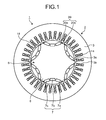
- FIG. 1 is a cross-sectional view of a permanent-magnet type electric motor, which is an example of a permanent-magnet type rotating electrical machine according to a first embodiment.
- FIG. 2 is a schematic cross-sectional view of a rotor, depicting a magnetic pole structure of a permanent magnet to be embedded in a rotor.
- FIG. 3 is a partial enlarged view of a portion indicated by a broken line in FIG. 2 when a permanent magnet is not inserted.
- FIG. 4 is a partial enlarged view corresponding to FIG. 3 when a permanent magnet is inserted.
- FIG. 5 is an explanatory diagram of detailed positions of flux control holes according to the first embodiment.
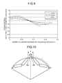
- FIG. 6 depicts a temporal change of torque ripples corresponding to the presence of flux control holes according to the first embodiment.
- FIG. 7 depicts a relation between a center-to-center distance of the flux control holes according to the first embodiment and amplitudes of torque ripples.
- FIG. 8 is an axial cross-sectional view of a flux control hole according to a second embodiment formed by a caulking structure.
- FIG. 9 depicts a relation between a center-to-center distance of the flux control holes according to the second embodiment formed by a caulking structure and a torque ripple amplitude.
- FIG. 10 is a schematic cross-sectional view of a part of a configuration of a rotor core of a permanent-magnet type rotating electrical machine according to a third embodiment.
- FIG. 11 depicts a relation between a center-to-center distance of flux control holes formed by a rotor configuration according to the third embodiment and a torque ripple amplitude (a simulation result).
- FIG. 12 is a schematic cross-sectional view of a part of a configuration of a rotor core of a permanent-magnet type rotating electrical machine according to a fourth embodiment.
- FIG. 1 is a cross-sectional view of a permanent-magnet type electric motor, which is an example of a permanent-magnet type rotating electrical machine according to a first embodiment
- FIG. 2 is a schematic cross-sectional view of a rotor, depicting a magnetic pole structure of a permanent magnet to be embedded in a rotor
- FIG. 3 is a partial enlarged view of a portion indicated by a broken line in FIG. 2 when a permanent magnet is not inserted
- FIG. 4 is a partial enlarged view corresponding to FIG. 3 when a permanent magnet is inserted.
- a permanent-magnet type electric motor 1 includes a stator 2 and a rotor 5 .
- the stator 2 includes a cylindrical stator core 3 and, for example, 36 teeth 3 b are formed on an inner circumference of the stator core 3 intermittently at an equiangular pitch to form 36 slots 3 a .
- a stator coil 4 is wound and accommodated in the slot 3 a so as to include a predetermined number of teeth 3 b therein.
- the rotor 5 includes a rotor core 6 produced by, for example, laminating and integrating a predetermined number of magnetic steel plates so that an outer periphery forms a cylindrical surface, and 18 magnet insertion holes 7 are arranged at an equiangular pitch, and permanent magnets 8 ( 8 a to 8 c: see FIGS. 2 and 4 ) and permanent magnets 16 ( 16 a to 16 c: see FIG. 2 ) respectively accommodated in each of the magnet insertion holes 7 .
- the rotor 5 is arranged rotatably with respect to the stator 2 via a rotation gap 18 .
- the arrangement of the magnet insertion holes 7 is such that, as shown in FIG. 3 , there are two magnet insertion holes 7 a and 7 c at both ends of one magnet insertion hole 7 b , and six sets of magnet insertion holes 7 are arranged (formed) in a substantially U-shape so as to open toward the outer periphery (outer circumferential direction) of the rotor core 6 .
- the permanent magnets 8 a to 8 c which are the first set of permanent magnets, are magnetized in a direction in which the magnetic flux converges toward the outer periphery of the rotor core 6 .
- the permanent magnets 16 a to 16 c of an adjacent set are magnetized in a direction in which the magnetic flux expands toward the center of the rotor core 6 . That is, in the rotor in the permanent-magnet type electric motor according to the first embodiment, a permanent magnet group magnetized in the direction in which the magnetic flux of the permanent magnet converges toward the outer periphery of the rotor and a permanent magnet group magnetized in the direction in which the magnetic flux expands toward the center of the rotor are arranged alternately.
- the magnetization direction of the permanent magnet group is set as described above so as to form an induced voltage of a stator coil in a sine wave form, and in an application in which the induced voltage of the stator coil does not need to be formed in a sine wave form, the direction of the magnetic flux is not limited to the direction described above. That is, respective magnetization directions of respective permanent magnet groups magnetized in the direction toward the outer periphery of the rotor and in the direction toward the center of the rotor can be parallel to each other.
- cavities 9 as shown in FIG. 4 are formed (cavities 9 a 1 and 9 a 2 are formed on the both sides of the permanent magnet 8 a , cavities 9 b 1 and 9 b 2 are formed on the both sides of the permanent magnet 8 b, and cavities 9 c 1 and 9 c 2 are formed on the both sides of the permanent magnet 8 c ).
- a flux control hole 20 a is provided around the cavity 9 c 2 formed in the permanent magnet 8 c in the first permanent magnet group, and a flux control hole 20 b is provided around a cavity 17 a 1 formed in the permanent magnet 16 a in the adjacent permanent magnet group.
- These flux control holes 20 a and 20 b can reduce torque ripples, and it is preferable to form the depth of holes approximately in the same thickness as that of the permanent magnet 8 to be embedded in the rotor core 6 .
- FIG. 1 depicts an electric motor in which 36 slots 3 a are arranged at an equiangular pitch in the circumferential direction of the stator 2 , 18 permanent magnets 8 and 16 that form six permanent magnet groups are embedded in the rotor core 6 in the circumferential direction, and six pairs (that is, 12) flux control holes 20 are provided in six magnetic pole gaps between the six permanent magnetic groups (six slots per pole, three permanent magnets per pole, and two flux control holes 20 per space between magnetic poles).
- the number of poles and the number of slots of the electric motor, the number of permanent magnets, the number of flux control holes, and the like are not limited to the configuration shown in FIG. 1 , and any number can be selected therefor.
- a center line 30 between magnetic poles, passing through the center of the rotor core 6 is drawn at an equal distance from the magnet insertion hole 7 c at the right end of the first permanent magnet group and a magnet insertion hole 15 a at the left end of the adjacent permanent magnet group.
- the flux control holes 20 a and 20 b are provided at the equal distance from the center line 30 between magnetic poles, that is, the flux control holes 20 a and 20 b are provided axisymmetrically with respect to the center line 30 between magnetic poles.
- FIG. 6 depicts a temporal change of torque ripples corresponding to the presence of the flux control holes 20 (a simulation result), with a rotational position of a motor being plotted on a horizontal axis and a torque being plotted on a vertical axis.
- a solid line indicates a case where the flux control holes 20 are provided, and a broken line indicates a case where the flux control holes 20 are not provided.
- torque ripples are considerably reduced by providing the flux control holes 20 .
- FIG. 7 depicts a relation between a center-to-center distance of the flux control holes 20 and amplitudes of torque ripples (a simulation result).
- a value obtained by standardizing the center-to-center distance of the flux control holes 20 a and 20 b by the pole pitch ⁇ of the magnet is plotted on a horizontal axis
- a value obtained by standardizing an amplitude value of torque ripples when having the flux control holes 20 by an amplitude value of torque ripples when the flux control holes 20 are not provided is plotted on a vertical axis, while designating the diameter of the flux control hole 20 (a standard value with respect to the pole pitch ⁇ ) as a parameter.
- a solid line indicates a case where each diameter of the flux control holes 20 a and 20 b is 0.026 ⁇
- a one-dot chain line indicates a case where each diameter of the flux control holes 20 a and 20 b is 0.036 ⁇
- a broken line indicates a case where each diameter of the flux control holes 20 a and 20 b is 0.046 ⁇ .
- the value of m/ ⁇ is set to less than 0.2.
- This condition maintains a condition such that parts of the flux control holes 20 a and 20 b do not overlap on the magnet insertion hole 7 c or the magnet insertion hole 15 a, that is, a condition of m ⁇ (b ⁇ 2 d)(m/ ⁇ (b ⁇ 2 d)/ ⁇ ) when a width of the magnetic pole gap between the first permanent magnet group and another permanent magnet group adjacent to the first permanent magnet group is assumed to be b.
- a pair of flux control holes is provided in a magnetic pole gap of a rotor, and it is set such that the pair of flux control holes does not overlap on each other, each of the flux control holes does not overlap on a part of the magnet insertion holes adjacent to each other, and the value (m/ ⁇ ) obtained by standardizing the center-to-center distance m of the pair of flux control holes by the pole pitch ⁇ becomes equal to or larger than 0.08. Therefore, the torque ripples can be reduced.
- this method is a simple method of providing holes in a part of a rotor core, high diametral accuracy of the rotor core can be easily achieved.
- the hole portion does not need to be a cavity (air), and a material having a lower magnetic permeability than that of a rotor core (resin or the like) can be embedded therein.
- FIG. 8 is an axial cross-sectional view of a flux control hole formed by a caulking structure.
- FIG. 9 depicts a relation between a center-to-center distance of the flux control holes 20 formed by a caulking structure and a torque ripple amplitude (a simulation result).
- the relation between the horizontal axis and the vertical axis, and the diameter of the flux control holes 20 as a parameter are the same as those of the first embodiment.
- the portion of the flux control hole 20 When the portion of the flux control hole 20 is formed by a caulking structure, the magnetic permeability of the portion of the flux control hole 20 becomes smaller than that of the rotor core 6 . Therefore, the configuration of the second embodiment becomes equivalent to that of the first embodiment, and torque ripples can be reduced.
- the axial direction of the rotor can be fixed by a caulking structure, and the machinability thereof can be improved. That is, by forming the portion of the flux control holes 20 by the caulking structure, an effect of bonding and integrating the magnetic steel plates that constitute the rotor core 6 and an effect of reducing torque ripples by controlling the magnetic flux in the rotor 2 can be simultaneously acquired.
- a pair of holes (caulking holes) having a caulking structure is provided in a magnetic pole gap of a rotor in such a manner that each one of a pair of caulking holes does not overlap on an adjacent magnet insertion hole, and the value (m/ ⁇ ) obtained by standardizing the center-to-center distance m of these caulking holes by the pole pitch ⁇ is set equal to or larger than 0.08. Accordingly, the pair of caulking holes functions as the flux control holes explained in the embodiment and torque ripples can be reduced. Furthermore, because this method is a simple method of providing a hole having a caulking structure in a part of a rotor core, the diametral accuracy of the rotor core is not degraded.
- FIG. 10 is a schematic cross-sectional view of a part of a configuration of a rotor core of a permanent-magnet type rotating electrical machine according to a third embodiment.
- three permanent magnets are arranged per pole in a substantially U-shape.
- two permanent magnets are arranged per pole in a V-shape, and the flux control holes 20 a and 20 b identical to those of the first embodiment are provided in a magnetic pole gap.
- FIG. 11 depicts a relation between a center-to-center distance of the flux control holes 20 formed by a rotor configuration according to the third embodiment and a torque ripple amplitude (a simulation result).
- the relation between the horizontal axis and the vertical axis, and the diameter of the flux control holes 20 as a parameter are the same as those of the first embodiment.
- the number of permanent magnets is one less than that of the first embodiment per pole, a process of inserting a magnet is reduced, and the machinability thereof can be improved.
- FIG. 12 is a schematic cross-sectional view of a part of a configuration of a rotor core of a permanent-magnet type rotating electrical machine according to a fourth embodiment.
- a detailed cross-sectional view of a rotor according to the fourth embodiment of the present invention is shown.
- FIGS. 3 and 4 when the permanent magnets are inserted into the three magnet insertion holes 7 a to 7 c , a cavity is formed on opposite sides of all the holes.
- any cavity is not formed on the respective inner sides of the magnet insertion holes 7 a and 7 c positioned on the opposite sides.
- the configuration described in the first to fourth embodiments is only an example of the configuration of the present invention, and it can be combined with other well-known techniques, and it is needless to mention that the present invention can be configured while modifying it without departing from the scope of the invention, such as omitting a part of the configuration.
- a configuration of a rotor in which two or three permanent magnets are arranged per pole in a V-shape or a U-shape toward the outer periphery that is, in a depressed shape toward the outer periphery or in a protruding shape toward the center of the rotor
- the number of permanent magnets can be four or more per pole. That is, in the permanent-magnet type rotating electrical machine according to the present invention, a plurality of permanent magnets can be arranged per pole in a depressed shape toward the outer periphery or in a protruding shape toward the center of the rotor.
- a permanent magnet having a substantially rectangular shape such as that shown in FIG. 4 has been exemplified as the permanent magnet 8 to be embedded in the magnet insertion hole 7 .
- the shape of the permanent magnet is not limited to such rectangular shape, and, for example, a trapezoidal shape can be also used.
- the shape of the flux control hole 20 is circular
- the shape is not limited to circular, and other shapes can be also used. Note that, in a case of a circular flux control hole, there is an advantage that machining thereof is facilitated, and thus it is effective in reducing the time of manufacturing processes.
- the present invention is useful as a permanent-magnet type rotating electrical machine that can reduce torque ripples while maintaining the diametral accuracy of a rotor core.
Landscapes
- Engineering & Computer Science (AREA)
- Power Engineering (AREA)
- Permanent Field Magnets Of Synchronous Machinery (AREA)
- Iron Core Of Rotating Electric Machines (AREA)
- Permanent Magnet Type Synchronous Machine (AREA)
Applications Claiming Priority (1)
| Application Number | Priority Date | Filing Date | Title |
|---|---|---|---|
| PCT/JP2011/061164 WO2012157056A1 (ja) | 2011-05-16 | 2011-05-16 | 永久磁石型回転電機 |
Publications (1)
| Publication Number | Publication Date |
|---|---|
| US20140091663A1 true US20140091663A1 (en) | 2014-04-03 |
Family
ID=47176425
Family Applications (1)
| Application Number | Title | Priority Date | Filing Date |
|---|---|---|---|
| US14/118,123 Abandoned US20140091663A1 (en) | 2011-05-16 | 2011-05-16 | Permanent-magnet type rotating electrical machine |
Country Status (5)
| Country | Link |
|---|---|
| US (1) | US20140091663A1 (ja) |
| EP (1) | EP2712058B1 (ja) |
| JP (1) | JP5372296B2 (ja) |
| CN (1) | CN103518313B (ja) |
| WO (1) | WO2012157056A1 (ja) |
Cited By (9)
| Publication number | Priority date | Publication date | Assignee | Title |
|---|---|---|---|---|
| US20130062889A1 (en) * | 2010-03-23 | 2013-03-14 | Adaptive Generators As | Variable electrical generator |
| US20150097458A1 (en) * | 2012-04-16 | 2015-04-09 | Otis Elevator Company | Permanent Magnet Electric Machine |
| US20150318742A1 (en) * | 2012-11-22 | 2015-11-05 | Xin Li | Electric machines, stators and compressors and methods of manufacturing same |
| US20170063211A1 (en) * | 2014-05-15 | 2017-03-02 | Fuji Electric Co., Ltd. | Permanent magnet embedded rotating electrical machine |
| US20170264151A1 (en) * | 2016-03-10 | 2017-09-14 | Kabushiki Kaisha Toyota Jidoshokki | Permanent magnet type rotating electric machine |
| US20190089212A1 (en) * | 2017-09-15 | 2019-03-21 | Ford Global Technologies, Llc | Rotor with nonmagnetic insert |
| US10361599B2 (en) * | 2015-09-29 | 2019-07-23 | Aisin Seiki Kabushiki Kaisha | Three-phase rotating electrical machine |
| US10720805B2 (en) | 2013-02-08 | 2020-07-21 | Fuji Electric Co., Ltd. | Embedded permanent magnet type rotating electric machine with permanent magnet rotor having magnet holes and central bridge |
| US11374449B2 (en) * | 2020-01-08 | 2022-06-28 | Hiwin Mikrosystem Corp. | Permanent-magnet spindle motor |
Families Citing this family (5)
| Publication number | Priority date | Publication date | Assignee | Title |
|---|---|---|---|---|
| DE102013201199A1 (de) * | 2013-01-25 | 2014-07-31 | Magna Powertrain Ag & Co. Kg | Elektrische Maschine und Verfahren zur Herstellung eines Elektroblechs |
| CN103414301B (zh) * | 2013-08-15 | 2016-05-25 | 南京信息工程大学 | 一种拼装式磁极的轴向磁场无铁心永磁电机 |
| JP6399071B2 (ja) * | 2016-10-05 | 2018-10-03 | マツダ株式会社 | 回転電機 |
| CN110089006B (zh) * | 2017-01-25 | 2020-07-14 | 三菱电机株式会社 | 转子及旋转电机 |
| US10749391B2 (en) * | 2017-03-06 | 2020-08-18 | Ford Global Technologies, Llc | Electric machine rotor |
Citations (15)
| Publication number | Priority date | Publication date | Assignee | Title |
|---|---|---|---|---|
| US4939398A (en) * | 1986-10-06 | 1990-07-03 | Emerson Electric Co. | Laminated assemblies with in situ molded magnets |
| US5757108A (en) * | 1995-03-03 | 1998-05-26 | Canon Kabushiki Kaisha | Motor |
| US20020047436A1 (en) * | 1998-09-29 | 2002-04-25 | Kazuto Sakai | Reluctance type rotating machine with permanent magnets |
| US20040007930A1 (en) * | 2002-04-15 | 2004-01-15 | Denso Corporation | Permanent-magnet rotor for an inner rotor type electric rotary machine and magnet-saving type rotor for a synchronous motor |
| US6946766B2 (en) * | 2002-08-28 | 2005-09-20 | Emerson Electric Co. | Permanent magnet machine |
| US20060103253A1 (en) * | 2002-06-20 | 2006-05-18 | Kabushiki Kaisha Toshiba | Rotor for permanent magnet motor of outer rotor type |
| US20070096578A1 (en) * | 2005-10-31 | 2007-05-03 | Jahns Thomas M | Device having permanent-magnet pieces |
| US7420306B2 (en) * | 2005-03-21 | 2008-09-02 | Samsung Electronics Co., Ltd. | Brushless DC motor |
| US20080272667A1 (en) * | 2007-05-04 | 2008-11-06 | A. O. Smith Corporation | Interior permanent magnet motor and rotor |
| US20090026867A1 (en) * | 2006-02-27 | 2009-01-29 | Kentaro Haruno | Rotor and electric vehicle |
| US7843101B2 (en) * | 2005-12-01 | 2010-11-30 | Aichi Elec Co. | Interior permanent magnet electric motor including a rotor having circumferential surface portions with defined curve profiles |
| JP2011015484A (ja) * | 2009-06-30 | 2011-01-20 | Mitsubishi Electric Corp | 永久磁石回転電機 |
| US8049388B2 (en) * | 2006-08-31 | 2011-11-01 | Abb Oy | Rotor for a permanent-magnet electrical machine |
| US20120091848A1 (en) * | 2008-11-19 | 2012-04-19 | Kabushkiki Kaisha Toshiba | Permanent magnet electric motor |
| US8227948B1 (en) * | 2009-01-09 | 2012-07-24 | Hydro-Gear Limited Partnership | Electric motor |
Family Cites Families (13)
| Publication number | Priority date | Publication date | Assignee | Title |
|---|---|---|---|---|
| JP3598804B2 (ja) * | 1998-04-10 | 2004-12-08 | 日産自動車株式会社 | 電動機のロータ |
| JP2000152539A (ja) * | 1998-11-17 | 2000-05-30 | Toyota Motor Corp | 永久磁石形電動機 |
| JP3616338B2 (ja) * | 2001-01-24 | 2005-02-02 | アイチエレック株式会社 | 電動機の回転子 |
| KR20020075993A (ko) * | 2001-03-27 | 2002-10-09 | 삼성광주전자 주식회사 | 동기모터의 회전자 및 그 제조방법 |
| JP2002305859A (ja) * | 2001-03-30 | 2002-10-18 | Aisin Aw Co Ltd | 永久磁石式同期電動機 |
| JP2004096925A (ja) * | 2002-09-02 | 2004-03-25 | Fuji Heavy Ind Ltd | 永久磁石型同期モータのロータ構造 |
| JP2007097387A (ja) * | 2005-08-31 | 2007-04-12 | Toshiba Corp | 回転電機 |
| JP4815967B2 (ja) * | 2005-09-21 | 2011-11-16 | トヨタ自動車株式会社 | 永久磁石式回転電機 |
| JP4900069B2 (ja) * | 2007-06-13 | 2012-03-21 | トヨタ自動車株式会社 | 回転電機 |
| JP5433198B2 (ja) * | 2008-10-16 | 2014-03-05 | 日立オートモティブシステムズ株式会社 | 回転電機及び電気自動車 |
| JP5278003B2 (ja) | 2009-01-30 | 2013-09-04 | トヨタ自動車株式会社 | 電動機 |
| US8242654B2 (en) * | 2009-05-20 | 2012-08-14 | Asmo Co., Ltd. | Rotor and motor |
| WO2011001533A1 (ja) * | 2009-07-03 | 2011-01-06 | 三菱電機株式会社 | 永久磁石型回転電機 |
-
2011
- 2011-05-16 EP EP11865546.3A patent/EP2712058B1/en active Active
- 2011-05-16 WO PCT/JP2011/061164 patent/WO2012157056A1/ja active Application Filing
- 2011-05-16 CN CN201180070835.9A patent/CN103518313B/zh active Active
- 2011-05-16 US US14/118,123 patent/US20140091663A1/en not_active Abandoned
- 2011-05-16 JP JP2013514879A patent/JP5372296B2/ja active Active
Patent Citations (15)
| Publication number | Priority date | Publication date | Assignee | Title |
|---|---|---|---|---|
| US4939398A (en) * | 1986-10-06 | 1990-07-03 | Emerson Electric Co. | Laminated assemblies with in situ molded magnets |
| US5757108A (en) * | 1995-03-03 | 1998-05-26 | Canon Kabushiki Kaisha | Motor |
| US20020047436A1 (en) * | 1998-09-29 | 2002-04-25 | Kazuto Sakai | Reluctance type rotating machine with permanent magnets |
| US20040007930A1 (en) * | 2002-04-15 | 2004-01-15 | Denso Corporation | Permanent-magnet rotor for an inner rotor type electric rotary machine and magnet-saving type rotor for a synchronous motor |
| US20060103253A1 (en) * | 2002-06-20 | 2006-05-18 | Kabushiki Kaisha Toshiba | Rotor for permanent magnet motor of outer rotor type |
| US6946766B2 (en) * | 2002-08-28 | 2005-09-20 | Emerson Electric Co. | Permanent magnet machine |
| US7420306B2 (en) * | 2005-03-21 | 2008-09-02 | Samsung Electronics Co., Ltd. | Brushless DC motor |
| US20070096578A1 (en) * | 2005-10-31 | 2007-05-03 | Jahns Thomas M | Device having permanent-magnet pieces |
| US7843101B2 (en) * | 2005-12-01 | 2010-11-30 | Aichi Elec Co. | Interior permanent magnet electric motor including a rotor having circumferential surface portions with defined curve profiles |
| US20090026867A1 (en) * | 2006-02-27 | 2009-01-29 | Kentaro Haruno | Rotor and electric vehicle |
| US8049388B2 (en) * | 2006-08-31 | 2011-11-01 | Abb Oy | Rotor for a permanent-magnet electrical machine |
| US20080272667A1 (en) * | 2007-05-04 | 2008-11-06 | A. O. Smith Corporation | Interior permanent magnet motor and rotor |
| US20120091848A1 (en) * | 2008-11-19 | 2012-04-19 | Kabushkiki Kaisha Toshiba | Permanent magnet electric motor |
| US8227948B1 (en) * | 2009-01-09 | 2012-07-24 | Hydro-Gear Limited Partnership | Electric motor |
| JP2011015484A (ja) * | 2009-06-30 | 2011-01-20 | Mitsubishi Electric Corp | 永久磁石回転電機 |
Cited By (13)
| Publication number | Priority date | Publication date | Assignee | Title |
|---|---|---|---|---|
| US20130062889A1 (en) * | 2010-03-23 | 2013-03-14 | Adaptive Generators As | Variable electrical generator |
| US8878373B2 (en) * | 2010-03-23 | 2014-11-04 | Adaptive Generators As | Variable electrical generator |
| US20150097458A1 (en) * | 2012-04-16 | 2015-04-09 | Otis Elevator Company | Permanent Magnet Electric Machine |
| US10141801B2 (en) * | 2012-11-22 | 2018-11-27 | Emerson Electric Co. | Electric machines, stators and compressors and methods of manufacturing same |
| US20150318742A1 (en) * | 2012-11-22 | 2015-11-05 | Xin Li | Electric machines, stators and compressors and methods of manufacturing same |
| US10720805B2 (en) | 2013-02-08 | 2020-07-21 | Fuji Electric Co., Ltd. | Embedded permanent magnet type rotating electric machine with permanent magnet rotor having magnet holes and central bridge |
| US20170063211A1 (en) * | 2014-05-15 | 2017-03-02 | Fuji Electric Co., Ltd. | Permanent magnet embedded rotating electrical machine |
| EP3145057B1 (en) * | 2014-05-15 | 2022-05-04 | Fuji Electric Co., Ltd. | Permanent magnet embedded rotating electrical machine |
| US10361599B2 (en) * | 2015-09-29 | 2019-07-23 | Aisin Seiki Kabushiki Kaisha | Three-phase rotating electrical machine |
| US20170264151A1 (en) * | 2016-03-10 | 2017-09-14 | Kabushiki Kaisha Toyota Jidoshokki | Permanent magnet type rotating electric machine |
| US10305337B2 (en) * | 2016-03-10 | 2019-05-28 | Kabushiki Kaisha Toyota Jidoshokki | Permanent magnet type rotating electric machine |
| US20190089212A1 (en) * | 2017-09-15 | 2019-03-21 | Ford Global Technologies, Llc | Rotor with nonmagnetic insert |
| US11374449B2 (en) * | 2020-01-08 | 2022-06-28 | Hiwin Mikrosystem Corp. | Permanent-magnet spindle motor |
Also Published As
| Publication number | Publication date |
|---|---|
| WO2012157056A1 (ja) | 2012-11-22 |
| EP2712058A4 (en) | 2015-12-30 |
| EP2712058A1 (en) | 2014-03-26 |
| EP2712058B1 (en) | 2019-09-11 |
| JP5372296B2 (ja) | 2013-12-18 |
| JPWO2012157056A1 (ja) | 2014-07-31 |
| CN103518313A (zh) | 2014-01-15 |
| CN103518313B (zh) | 2016-12-21 |
Similar Documents
| Publication | Publication Date | Title |
|---|---|---|
| US20140091663A1 (en) | Permanent-magnet type rotating electrical machine | |
| EP2667483B1 (en) | Rotor and motor including rotor | |
| CN103095011B (zh) | 转子铁心、转子以及旋转电机 | |
| CN109510347B (zh) | 旋转电机 | |
| US9172279B2 (en) | Automotive embedded permanent magnet rotary electric machine | |
| JP5811565B2 (ja) | 回転子および永久磁石電動機 | |
| EP2800243B1 (en) | Rotor or permanent magnet embedded motor, and compressor, blower, and refrigerating/aitr conditioning device using the rotor | |
| US9024498B2 (en) | Rotating electrical machine | |
| CN104953737B (zh) | 一种永磁无刷电机 | |
| JP5811567B2 (ja) | 回転子および永久磁石電動機 | |
| CN111052546B (zh) | 旋转电机的转子 | |
| KR101481882B1 (ko) | 회전 전기기계 | |
| JP2014050211A (ja) | 永久磁石回転電機 | |
| KR20130103643A (ko) | 매립형 영구자석 전동기 | |
| US10014736B2 (en) | Permanent magnet-embedded motor and rotor thereof | |
| JP2014045634A (ja) | ロータ及びこのロータを備える回転電機 | |
| KR101473086B1 (ko) | 회전 전기기계 | |
| JP2014155415A (ja) | 磁石埋込型ロータ及び磁石埋込型ロータの製造方法 | |
| EP2953240A1 (en) | Rotor and motor | |
| JP5954279B2 (ja) | 回転電機 | |
| US11901773B2 (en) | Rotating electric machine | |
| JP2017055560A (ja) | 永久磁石式回転電機 | |
| JP5959616B2 (ja) | 永久磁石埋込型モータの回転子並びに圧縮機及び冷凍空調装置 | |
| JP2015050803A (ja) | 回転電機 | |
| JP2017046386A (ja) | 永久磁石電動機 |
Legal Events
| Date | Code | Title | Description |
|---|---|---|---|
| AS | Assignment |
Owner name: MITSUBISHI ELECTRIC CORPORATION, JAPAN Free format text: ASSIGNMENT OF ASSIGNORS INTEREST;ASSIGNORS:HAZEYAMA, MORIYUKI;KANEKO, KENTA;INOUE, MASAYA;SIGNING DATES FROM 20131016 TO 20131018;REEL/FRAME:031614/0964 |
|
| STCB | Information on status: application discontinuation |
Free format text: ABANDONED -- FAILURE TO RESPOND TO AN OFFICE ACTION |