US20080098986A1 - ETC control system and method - Google Patents
ETC control system and method Download PDFInfo
- Publication number
- US20080098986A1 US20080098986A1 US11/590,304 US59030406A US2008098986A1 US 20080098986 A1 US20080098986 A1 US 20080098986A1 US 59030406 A US59030406 A US 59030406A US 2008098986 A1 US2008098986 A1 US 2008098986A1
- Authority
- US
- United States
- Prior art keywords
- engine
- throttle
- condition
- detecting
- throttle plate
- Prior art date
- Legal status (The legal status is an assumption and is not a legal conclusion. Google has not performed a legal analysis and makes no representation as to the accuracy of the status listed.)
- Granted
Links
- 238000000034 method Methods 0.000 title claims abstract description 14
- XLYOFNOQVPJJNP-UHFFFAOYSA-N water Substances O XLYOFNOQVPJJNP-UHFFFAOYSA-N 0.000 claims description 11
- 238000007710 freezing Methods 0.000 claims description 6
- 230000008014 freezing Effects 0.000 claims description 5
- 239000000571 coke Substances 0.000 description 3
- 239000013078 crystal Substances 0.000 description 3
- 230000015572 biosynthetic process Effects 0.000 description 2
- 230000006266 hibernation Effects 0.000 description 2
- 238000002485 combustion reaction Methods 0.000 description 1
- 238000001514 detection method Methods 0.000 description 1
- 238000010586 diagram Methods 0.000 description 1
- 230000000737 periodic effect Effects 0.000 description 1
- 230000006641 stabilisation Effects 0.000 description 1
- 238000011105 stabilization Methods 0.000 description 1
Images

Classifications
-
- F—MECHANICAL ENGINEERING; LIGHTING; HEATING; WEAPONS; BLASTING
- F02—COMBUSTION ENGINES; HOT-GAS OR COMBUSTION-PRODUCT ENGINE PLANTS
- F02D—CONTROLLING COMBUSTION ENGINES
- F02D41/00—Electrical control of supply of combustible mixture or its constituents
- F02D41/02—Circuit arrangements for generating control signals
- F02D41/04—Introducing corrections for particular operating conditions
- F02D41/042—Introducing corrections for particular operating conditions for stopping the engine
-
- F—MECHANICAL ENGINEERING; LIGHTING; HEATING; WEAPONS; BLASTING
- F02—COMBUSTION ENGINES; HOT-GAS OR COMBUSTION-PRODUCT ENGINE PLANTS
- F02D—CONTROLLING COMBUSTION ENGINES
- F02D11/00—Arrangements for, or adaptations to, non-automatic engine control initiation means, e.g. operator initiated
- F02D11/06—Arrangements for, or adaptations to, non-automatic engine control initiation means, e.g. operator initiated characterised by non-mechanical control linkages, e.g. fluid control linkages or by control linkages with power drive or assistance
- F02D11/10—Arrangements for, or adaptations to, non-automatic engine control initiation means, e.g. operator initiated characterised by non-mechanical control linkages, e.g. fluid control linkages or by control linkages with power drive or assistance of the electric type
- F02D11/107—Safety-related aspects
-
- F—MECHANICAL ENGINEERING; LIGHTING; HEATING; WEAPONS; BLASTING
- F02—COMBUSTION ENGINES; HOT-GAS OR COMBUSTION-PRODUCT ENGINE PLANTS
- F02D—CONTROLLING COMBUSTION ENGINES
- F02D11/00—Arrangements for, or adaptations to, non-automatic engine control initiation means, e.g. operator initiated
- F02D11/06—Arrangements for, or adaptations to, non-automatic engine control initiation means, e.g. operator initiated characterised by non-mechanical control linkages, e.g. fluid control linkages or by control linkages with power drive or assistance
- F02D11/10—Arrangements for, or adaptations to, non-automatic engine control initiation means, e.g. operator initiated characterised by non-mechanical control linkages, e.g. fluid control linkages or by control linkages with power drive or assistance of the electric type
- F02D2011/108—Arrangements for, or adaptations to, non-automatic engine control initiation means, e.g. operator initiated characterised by non-mechanical control linkages, e.g. fluid control linkages or by control linkages with power drive or assistance of the electric type with means for detecting or resolving a stuck throttle, e.g. when being frozen in a position
-
- F—MECHANICAL ENGINEERING; LIGHTING; HEATING; WEAPONS; BLASTING
- F02—COMBUSTION ENGINES; HOT-GAS OR COMBUSTION-PRODUCT ENGINE PLANTS
- F02D—CONTROLLING COMBUSTION ENGINES
- F02D2200/00—Input parameters for engine control
- F02D2200/02—Input parameters for engine control the parameters being related to the engine
- F02D2200/04—Engine intake system parameters
- F02D2200/0414—Air temperature
Definitions
- the present invention relates to electronic throttle control (ETC) systems, and more particularly to ETC systems and methods for clearing water, ice or other matter from around a throttle plate during engine soak.
- ETC electronic throttle control
- ETCs Electronic throttle controls or “ETCs” are well known for controlling the movement of a throttle plate within a throttle body that operates to control the amount of air delivered to an internal combustion engine.
- the ETC receives signals from the engine and/or the electronic control unit (ECU) of the vehicle directing the ETC to move the throttle plate to a degree dictated by the air requirements of the engine condition. It is also known that the throttle plate may sometimes become stuck due to icing or coke formation, for example. When this occurs, the ETC sets throttle actuation faults directing the throttle blade to move to a slightly open position which allows only enough air to reach the engine for a “limp home” condition. If the throttle is stuck in a near or fully open position, the ETC system detects this and reduces the available power to idle only or may completely disable the engine in some cases.
- ETC systems have been developed in the past directed toward removing the obstruction from the throttle plate such as seen in commonly owned, co-pending U.S. patent application Ser. No. 11/262,022, the disclosure of which is incorporated herein by reference.
- a piezo electronic actuator is disclosed which is operable to apply a high force to the throttle plate gear to free the plate from the stuck position. While the system of the '022 application provides an effective means for freeing a stuck throttle blade, it works from the standpoint that an obstruction has already formed which is preventing the throttle plate from moving correctly. Furthermore, should the obstruction become very large, the force required to free the stuck throttle plate may exceed the maximum force of the piezo actuator.
- the temperature of the engine and surrounding components can be very hot. Once the engine is shut off, the engine begins to cool until it is in equilibrium with the ambient temperature. The period of time from engine shut off to engine temperature equilibrium with the ambient is termed “engine soak” to the those skilled in the art. In cold climates, the engine temperature can thus dip below freezing temperatures as it goes through engine soak. In this situation, any moisture around the throttle plate will freeze and present a potential block to proper throttle movement once the engine is started again. Other matter such as coke can also form around a throttle plate.
- the present invention successfully addresses the above stated need by providing an ETC system and method which operates when the engine is off and during engine soak by detecting freezing or near-freezing temperatures and responding by moving the throttle blade to clear any water and ice crystals which may have accumulated near the throttle plate.
- This clearing function may be done at selected intervals for a predetermined period of time as described in more detail below.
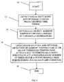
- FIG. 1 is a flow diagram illustrating the basic steps involved in accordance with the invention.
- the basic steps of the inventive system and method is seen for clearing water, ice or other potential obstructions near the throttle plate of a throttle body via the ETC of a vehicle (not shown).
- the ETC is programmed to operate the throttle which provides air to a vehicle engine in amounts dictated by the engine condition.
- the system and method starts at block and proceeds by detecting an “engine off” condition. When the engine is turned off, the ETC begins to shut down to a hibernation mode. Once the engine is off, a timer may be started to measure a predetermined time period as indicated at block 12 .
- the time period is chosen according to the expected stabilization soak time of the vehicle engine, i.e., the time period following engine shut off required for the throttle temperature to equalize to the outside temperature. It is during this time period that water may accumulate and then, if the ambient temperature is cold enough, freeze around the throttle plate, thereby creating an obstruction to the proper movement of the throttle plate once the engine is started again.
- the inventive method periodically “wakes up” the hibernating ECU one or more times which moves the throttle plate during this engine soak time to clear away any water and ice crystals (or other matter) forming around the throttle plate.
- the ambient temperature or the temperature near the throttle plate is monitored as at block 14 .
- a signal is sent (e.g. from the engine control unit or computer) to the ETC causing movement of the throttle plate as shown at block 16 .
- This movement of the throttle blade acts to clear water, ice crystals or other matter (e.g. coke) that may have begun forming around the throttle blade. This movement of the throttle blade thus prevents formation of an obstruction that would otherwise prevent the throttle from operating properly once the engine is started again.
- an alternate embodiment of the invention may cause the throttle clearing function to operate at the engine-off condition without detecting and thus regardless of the ambient temperature.
- the throttle clearing function Upon the earlier of the expiration of the predetermined time period or starting of the engine, the throttle clearing function is ended as at block 18 . If desired, rather than timing the throttle clearing function, the system may be designed such that the throttle clearing function will cease upon the earlier of a predetermined number of periodic throttle clearing movements or starting of the engine. Once the throttle clearing function has ceased, the ETC may return to its normal engine-off hibernation mode until key-up or engine start. The throttle clearing function resets and reinitiates upon detection of subsequent engine shut-off conditions.
- power consumption may be monitored at the vehicle battery to prevent a near or total battery drainage situation. If the battery condition is low, the function can be disabled so that the battery power is maintained for vehicle operation.
- the vehicle's Powertrain/Engine electronic control systems may be designed to ensure minimum power drainage caused by the operation of the throttle obstruction clearing system and method.
Landscapes
- Engineering & Computer Science (AREA)
- Chemical & Material Sciences (AREA)
- Combustion & Propulsion (AREA)
- Mechanical Engineering (AREA)
- General Engineering & Computer Science (AREA)
- Control Of Throttle Valves Provided In The Intake System Or In The Exhaust System (AREA)
Abstract
An electronic throttle control system and method which prevents obstructions from forming around a throttle plate during engine soak.
Description
- The present invention relates to electronic throttle control (ETC) systems, and more particularly to ETC systems and methods for clearing water, ice or other matter from around a throttle plate during engine soak.
- Electronic throttle controls or “ETCs” are well known for controlling the movement of a throttle plate within a throttle body that operates to control the amount of air delivered to an internal combustion engine. The ETC receives signals from the engine and/or the electronic control unit (ECU) of the vehicle directing the ETC to move the throttle plate to a degree dictated by the air requirements of the engine condition. It is also known that the throttle plate may sometimes become stuck due to icing or coke formation, for example. When this occurs, the ETC sets throttle actuation faults directing the throttle blade to move to a slightly open position which allows only enough air to reach the engine for a “limp home” condition. If the throttle is stuck in a near or fully open position, the ETC system detects this and reduces the available power to idle only or may completely disable the engine in some cases.
- ETC systems have been developed in the past directed toward removing the obstruction from the throttle plate such as seen in commonly owned, co-pending U.S. patent application Ser. No. 11/262,022, the disclosure of which is incorporated herein by reference. In the '022 application, a piezo electronic actuator is disclosed which is operable to apply a high force to the throttle plate gear to free the plate from the stuck position. While the system of the '022 application provides an effective means for freeing a stuck throttle blade, it works from the standpoint that an obstruction has already formed which is preventing the throttle plate from moving correctly. Furthermore, should the obstruction become very large, the force required to free the stuck throttle plate may exceed the maximum force of the piezo actuator.
- When an engine is running, the temperature of the engine and surrounding components can be very hot. Once the engine is shut off, the engine begins to cool until it is in equilibrium with the ambient temperature. The period of time from engine shut off to engine temperature equilibrium with the ambient is termed “engine soak” to the those skilled in the art. In cold climates, the engine temperature can thus dip below freezing temperatures as it goes through engine soak. In this situation, any moisture around the throttle plate will freeze and present a potential block to proper throttle movement once the engine is started again. Other matter such as coke can also form around a throttle plate.
- There therefore exists a need for an ETC system and method directed at clearing potential or partly formed obstructions near the throttle plate during engine soak.
- The present invention successfully addresses the above stated need by providing an ETC system and method which operates when the engine is off and during engine soak by detecting freezing or near-freezing temperatures and responding by moving the throttle blade to clear any water and ice crystals which may have accumulated near the throttle plate. This clearing function may be done at selected intervals for a predetermined period of time as described in more detail below.
- The present invention will now be described, by way of example, with reference to the accompanying drawings, in which:
-
FIG. 1 is a flow diagram illustrating the basic steps involved in accordance with the invention. - Referring to
FIG. 1 , the basic steps of the inventive system and method is seen for clearing water, ice or other potential obstructions near the throttle plate of a throttle body via the ETC of a vehicle (not shown). As is well known, the ETC is programmed to operate the throttle which provides air to a vehicle engine in amounts dictated by the engine condition. The system and method starts at block and proceeds by detecting an “engine off” condition. When the engine is turned off, the ETC begins to shut down to a hibernation mode. Once the engine is off, a timer may be started to measure a predetermined time period as indicated atblock 12. The time period is chosen according to the expected stabilization soak time of the vehicle engine, i.e., the time period following engine shut off required for the throttle temperature to equalize to the outside temperature. It is during this time period that water may accumulate and then, if the ambient temperature is cold enough, freeze around the throttle plate, thereby creating an obstruction to the proper movement of the throttle plate once the engine is started again. The inventive method periodically “wakes up” the hibernating ECU one or more times which moves the throttle plate during this engine soak time to clear away any water and ice crystals (or other matter) forming around the throttle plate. - In this embodiment of the invention, during the predetermined time period, the ambient temperature or the temperature near the throttle plate is monitored as at
block 14. Upon detecting a temperature near or below a threshold temperature such as the freezing temperature of water, a signal is sent (e.g. from the engine control unit or computer) to the ETC causing movement of the throttle plate as shown atblock 16. This movement of the throttle blade acts to clear water, ice crystals or other matter (e.g. coke) that may have begun forming around the throttle blade. This movement of the throttle blade thus prevents formation of an obstruction that would otherwise prevent the throttle from operating properly once the engine is started again. - Although this embodiment of the invention operates the throttle clearing function only if the ambient temperature is near or below a threshold temperature, an alternate embodiment of the invention may cause the throttle clearing function to operate at the engine-off condition without detecting and thus regardless of the ambient temperature.
- Upon the earlier of the expiration of the predetermined time period or starting of the engine, the throttle clearing function is ended as at
block 18. If desired, rather than timing the throttle clearing function, the system may be designed such that the throttle clearing function will cease upon the earlier of a predetermined number of periodic throttle clearing movements or starting of the engine. Once the throttle clearing function has ceased, the ETC may return to its normal engine-off hibernation mode until key-up or engine start. The throttle clearing function resets and reinitiates upon detection of subsequent engine shut-off conditions. - If desired, power consumption may be monitored at the vehicle battery to prevent a near or total battery drainage situation. If the battery condition is low, the function can be disabled so that the battery power is maintained for vehicle operation. The vehicle's Powertrain/Engine electronic control systems may be designed to ensure minimum power drainage caused by the operation of the throttle obstruction clearing system and method.
- While the invention has been described by reference to various specific embodiments, it should be understood that numerous changes may be made within the spirit and scope of the inventive concepts described. Accordingly, it is intended that the invention not be limited to the described embodiments, but will have full scope defined by the language of the following claims.
Claims (11)
1. A method for clearing water, ice or other matter from around a throttle plate of a throttle body operable to provide air to a vehicle engine, said method comprising the steps of:
a) providing an electronic throttle control operable to control the movement of said throttle plate;
b) detecting an engine-off condition;
c) detecting an ambient temperature and comparing said detected temperature to a predetermined threshold temperature, said predetermined threshold temperature being at or below a freezing temperature of water; and
d) upon detecting an engine-off condition and that said ambient temperature is at or below said predetermined threshold temperature, causing said electronic throttle control to move said throttle plate one or more times at selected intervals during said engine-off condition.
2. The method of claim 1 wherein said throttle plate is moved at selected intervals for a predetermined period of time during said engine-off condition.
3. The method of claim 1 wherein said throttle plate is moved a predetermined number of times during said engine-off condition.
4. (canceled)
5. (canceled)
6. The method of claim 1 and further comprising the step of:
a) upon detecting a low vehicle engine battery condition, stopping said movement of said throttle.
7. A system for clearing water, ice or other matter around The a throttle plate of a throttle body operable to provide air to a vehicle engine, said system comprising:
a) an electronic throttle control operable to control the movement of said throttle plate; and
b) a first detector for detecting an engine-off condition;
c) a second detector for detecting an ambient temperature and comparing said detected temperature to a predetermined threshold temperature, said predetermined threshold temperature being at or below a freezing temperature of water;
whereby said electronic throttle control moves said throttle plate at selected intervals during said engine-off condition upon said first detector detecting an engine-off condition and said second detector detecting that said ambient temperature is at or below said predetermined threshold temperature.
8. The system of claim 7 wherein said electronic throttle control moves said throttle plate at selected intervals for a predetermined period of time during said engine-off condition.
9. The system of claim 7 wherein said electronic throttle control moves said throttle plate a predetermined number of times during said engine-off condition.
10-13. (canceled)
14. The system of claim 7 and further comprising a detector for detecting a low vehicle battery condition;
whereby further movement of said throttle blade during said engine-off condition is ceased upon detecting said low vehicle battery condition.
Priority Applications (1)
| Application Number | Priority Date | Filing Date | Title |
|---|---|---|---|
| US11/590,304 US7434566B2 (en) | 2006-10-31 | 2006-10-31 | ETC control system and method |
Applications Claiming Priority (1)
| Application Number | Priority Date | Filing Date | Title |
|---|---|---|---|
| US11/590,304 US7434566B2 (en) | 2006-10-31 | 2006-10-31 | ETC control system and method |
Publications (2)
| Publication Number | Publication Date |
|---|---|
| US20080098986A1 true US20080098986A1 (en) | 2008-05-01 |
| US7434566B2 US7434566B2 (en) | 2008-10-14 |
Family
ID=39328635
Family Applications (1)
| Application Number | Title | Priority Date | Filing Date |
|---|---|---|---|
| US11/590,304 Expired - Fee Related US7434566B2 (en) | 2006-10-31 | 2006-10-31 | ETC control system and method |
Country Status (1)
| Country | Link |
|---|---|
| US (1) | US7434566B2 (en) |
Cited By (10)
| Publication number | Priority date | Publication date | Assignee | Title |
|---|---|---|---|---|
| US20120006003A1 (en) * | 2010-07-08 | 2012-01-12 | Gm Global Technology Operations, Inc. | Method of operating a vehicle under frozen diesel emission fluid conditions |
| US20130297176A1 (en) * | 2012-05-04 | 2013-11-07 | Cummins Ip, Inc | Engine off time tracking |
| CN106555687A (en) * | 2015-09-30 | 2017-04-05 | 上海汽车集团股份有限公司 | Vehicle motor air throttle valve plate control method and device |
| EP3379059A1 (en) * | 2017-03-22 | 2018-09-26 | Toyota Jidosha Kabushiki Kaisha | Control apparatus for internal combustion engine and control method for internal combustion engine |
| US10100762B2 (en) * | 2015-04-09 | 2018-10-16 | Toyota Jidosha Kabushiki Kaisha | Engine control device |
| EP3388655A1 (en) * | 2017-04-11 | 2018-10-17 | Toyota Jidosha Kabushiki Kaisha | Control device for internal combustion engine |
| US10280823B2 (en) | 2015-08-25 | 2019-05-07 | Toyota Jidosha Kabushiki Kaisha | Engine control device |
| US11092114B2 (en) * | 2017-09-15 | 2021-08-17 | Hitachi Automotive Systems, Ltd. | Vehicle control device |
| CN114658551A (en) * | 2021-04-20 | 2022-06-24 | 长城汽车股份有限公司 | Throttle valve, automobile and throttle valve deicing method |
| JP2023160292A (en) * | 2022-04-22 | 2023-11-02 | トヨタ自動車株式会社 | vehicle |
Families Citing this family (2)
| Publication number | Priority date | Publication date | Assignee | Title |
|---|---|---|---|---|
| JP5393506B2 (en) * | 2010-01-27 | 2014-01-22 | 三菱重工業株式会社 | Control device and control method for control valve used in engine intake system |
| US11753974B2 (en) * | 2021-11-05 | 2023-09-12 | Ford Global Technologies, Llc | Methods and system for de-icing a valve of an exhaust system |
Citations (10)
| Publication number | Priority date | Publication date | Assignee | Title |
|---|---|---|---|---|
| US6167866B1 (en) * | 1998-09-07 | 2001-01-02 | Robert Bosch Gmbh | Control device for controlling the power of a driving engine |
| US6345604B1 (en) * | 2000-05-17 | 2002-02-12 | Visteon Global Technologies, Inc. | Electronically controlled throttle valve with commanded default position for the throttle valve of an internal combustion engine |
| US6431144B1 (en) * | 1999-09-02 | 2002-08-13 | Siemens Vdo Automotive Inc. | Electronic throttle control system |
| US6786199B2 (en) * | 2001-08-01 | 2004-09-07 | Toyoda Boshoku Corporation | Hydrocarbons emission preventive apparatus in intake system for internal combustion engine and method thereof |
| US20040182370A1 (en) * | 2003-03-17 | 2004-09-23 | Visteon Global Technologies, Inc. | Electrically heated throttle body |
| US20060037473A1 (en) * | 2004-08-17 | 2006-02-23 | Siemens Vdo Automotive Inc. | Coating for a throttle body |
| US7114487B2 (en) * | 2004-01-16 | 2006-10-03 | Ford Motor Company | Ice-breaking, autozero and frozen throttle plate detection at power-up for electronic motorized throttle |
| US7159563B1 (en) * | 2005-10-28 | 2007-01-09 | Delphi Technologies, Inc. | Piezo electronic throttle control actuator |
| US20070084438A1 (en) * | 2005-10-17 | 2007-04-19 | Garrick Robert D | Throttle default system |
| US7210452B2 (en) * | 2005-07-19 | 2007-05-01 | Mitsubishi Denki Kabushiki Kaisha | Control apparatus of internal combustion engine |
Family Cites Families (3)
| Publication number | Priority date | Publication date | Assignee | Title |
|---|---|---|---|---|
| DE3743309A1 (en) | 1987-12-21 | 1989-06-29 | Bosch Gmbh Robert | METHOD AND DEVICE FOR DETECTING AND RELAXING CLAMPED CONTROL ELEMENTS |
| US5912538A (en) * | 1998-05-12 | 1999-06-15 | Eaton Corporation | Torque amplification for ice breaking in an electric torque motor |
| DE102004057612B4 (en) | 2003-12-03 | 2010-04-08 | Continental Automotive Systems US, Inc. (n. d. Gesetzen des Staates Delaware), Auburn Hills | Electronic control system for a throttle body and method |
-
2006
- 2006-10-31 US US11/590,304 patent/US7434566B2/en not_active Expired - Fee Related
Patent Citations (10)
| Publication number | Priority date | Publication date | Assignee | Title |
|---|---|---|---|---|
| US6167866B1 (en) * | 1998-09-07 | 2001-01-02 | Robert Bosch Gmbh | Control device for controlling the power of a driving engine |
| US6431144B1 (en) * | 1999-09-02 | 2002-08-13 | Siemens Vdo Automotive Inc. | Electronic throttle control system |
| US6345604B1 (en) * | 2000-05-17 | 2002-02-12 | Visteon Global Technologies, Inc. | Electronically controlled throttle valve with commanded default position for the throttle valve of an internal combustion engine |
| US6786199B2 (en) * | 2001-08-01 | 2004-09-07 | Toyoda Boshoku Corporation | Hydrocarbons emission preventive apparatus in intake system for internal combustion engine and method thereof |
| US20040182370A1 (en) * | 2003-03-17 | 2004-09-23 | Visteon Global Technologies, Inc. | Electrically heated throttle body |
| US7114487B2 (en) * | 2004-01-16 | 2006-10-03 | Ford Motor Company | Ice-breaking, autozero and frozen throttle plate detection at power-up for electronic motorized throttle |
| US20060037473A1 (en) * | 2004-08-17 | 2006-02-23 | Siemens Vdo Automotive Inc. | Coating for a throttle body |
| US7210452B2 (en) * | 2005-07-19 | 2007-05-01 | Mitsubishi Denki Kabushiki Kaisha | Control apparatus of internal combustion engine |
| US20070084438A1 (en) * | 2005-10-17 | 2007-04-19 | Garrick Robert D | Throttle default system |
| US7159563B1 (en) * | 2005-10-28 | 2007-01-09 | Delphi Technologies, Inc. | Piezo electronic throttle control actuator |
Cited By (13)
| Publication number | Priority date | Publication date | Assignee | Title |
|---|---|---|---|---|
| US20120006003A1 (en) * | 2010-07-08 | 2012-01-12 | Gm Global Technology Operations, Inc. | Method of operating a vehicle under frozen diesel emission fluid conditions |
| US9797288B2 (en) * | 2010-07-08 | 2017-10-24 | GM Global Technology Operations LLC | Method of operating a vehicle under frozen diesel emission fluid conditions |
| US20130297176A1 (en) * | 2012-05-04 | 2013-11-07 | Cummins Ip, Inc | Engine off time tracking |
| US9080519B2 (en) * | 2012-05-04 | 2015-07-14 | Cummins Ip, Inc. | Engine off time tracking |
| US10100762B2 (en) * | 2015-04-09 | 2018-10-16 | Toyota Jidosha Kabushiki Kaisha | Engine control device |
| US10280823B2 (en) | 2015-08-25 | 2019-05-07 | Toyota Jidosha Kabushiki Kaisha | Engine control device |
| CN106555687A (en) * | 2015-09-30 | 2017-04-05 | 上海汽车集团股份有限公司 | Vehicle motor air throttle valve plate control method and device |
| EP3379059A1 (en) * | 2017-03-22 | 2018-09-26 | Toyota Jidosha Kabushiki Kaisha | Control apparatus for internal combustion engine and control method for internal combustion engine |
| EP3388655A1 (en) * | 2017-04-11 | 2018-10-17 | Toyota Jidosha Kabushiki Kaisha | Control device for internal combustion engine |
| US11092114B2 (en) * | 2017-09-15 | 2021-08-17 | Hitachi Automotive Systems, Ltd. | Vehicle control device |
| CN114658551A (en) * | 2021-04-20 | 2022-06-24 | 长城汽车股份有限公司 | Throttle valve, automobile and throttle valve deicing method |
| JP2023160292A (en) * | 2022-04-22 | 2023-11-02 | トヨタ自動車株式会社 | vehicle |
| JP7707995B2 (en) | 2022-04-22 | 2025-07-15 | トヨタ自動車株式会社 | vehicle |
Also Published As
| Publication number | Publication date |
|---|---|
| US7434566B2 (en) | 2008-10-14 |
Similar Documents
| Publication | Publication Date | Title |
|---|---|---|
| US7434566B2 (en) | ETC control system and method | |
| US7509939B2 (en) | Throttle control apparatus for internal combustion engine | |
| EP3150829B1 (en) | Apparatus and method for controlling engine | |
| JP2005098138A (en) | Fuel pressure control device for in-cylinder internal combustion engine | |
| JP3474872B2 (en) | Throttle control device for internal combustion engine | |
| US7503311B2 (en) | Method for sensing and clearing throttle plate obstruction | |
| US8474310B2 (en) | Valve freeze control apparatus and sensor element breakage control apparatus for internal combustion engine | |
| WO2022267997A1 (en) | Engine control method and apparatus, device, program, and storage medium | |
| US7114487B2 (en) | Ice-breaking, autozero and frozen throttle plate detection at power-up for electronic motorized throttle | |
| JP5747897B2 (en) | Internal combustion engine control method and internal combustion engine control apparatus | |
| CN101663480B (en) | Method for controlling an automatic switching off process for an internal combustion engine | |
| KR101500350B1 (en) | Ammonia injection control method when nox sensor is not operated | |
| US7100570B2 (en) | Throttle control system and method | |
| JP4378641B2 (en) | Throttle control device for internal combustion engine | |
| JP5054721B2 (en) | Fuel injection control device for internal combustion engine | |
| CN117167154A (en) | A method for judging and treating low-temperature icing stuck in the exhaust gas recirculation valve | |
| EP2221464A1 (en) | Control unit for internal combustion engine | |
| JP4894812B2 (en) | Fuel injection device | |
| JP4697129B2 (en) | Control device for internal combustion engine | |
| KR20070028017A (en) | How to control startability of vehicles equipped with Elpiai engine | |
| JP3939677B2 (en) | Cylinder deactivation control method for hydraulically controlled cylinder deactivation engine | |
| JP6419668B2 (en) | Control device for internal combustion engine | |
| JPH07103077A (en) | Exhaust gas recirculation control device for internal combustion engine | |
| JPH09203363A (en) | Anti-icing device for fuel injection valve | |
| US7499790B2 (en) | Method for the plausibility check of the shut-down time of a motor vehicle with an internal combustion engine |
Legal Events
| Date | Code | Title | Description |
|---|---|---|---|
| AS | Assignment |
Owner name: DELPHI TECHNOLOGIES, INC., MICHIGAN Free format text: ASSIGNMENT OF ASSIGNORS INTEREST;ASSIGNORS:MCKAY, DANIEL L.;NICHOLS, GARY A.;WILLIAMS (GUILLAUME), CARELTON;REEL/FRAME:018489/0478 Effective date: 20061030 |
|
| REMI | Maintenance fee reminder mailed | ||
| LAPS | Lapse for failure to pay maintenance fees | ||
| STCH | Information on status: patent discontinuation |
Free format text: PATENT EXPIRED DUE TO NONPAYMENT OF MAINTENANCE FEES UNDER 37 CFR 1.362 |
|
| FP | Lapsed due to failure to pay maintenance fee |
Effective date: 20121014 |