EP3379059A1 - Control apparatus for internal combustion engine and control method for internal combustion engine - Google Patents
Control apparatus for internal combustion engine and control method for internal combustion engine Download PDFInfo
- Publication number
- EP3379059A1 EP3379059A1 EP18163362.9A EP18163362A EP3379059A1 EP 3379059 A1 EP3379059 A1 EP 3379059A1 EP 18163362 A EP18163362 A EP 18163362A EP 3379059 A1 EP3379059 A1 EP 3379059A1
- Authority
- EP
- European Patent Office
- Prior art keywords
- ports
- condensate water
- internal combustion
- intake
- combustion engine
- Prior art date
- Legal status (The legal status is an assumption and is not a legal conclusion. Google has not performed a legal analysis and makes no representation as to the accuracy of the status listed.)
- Granted
Links
- 238000002485 combustion reaction Methods 0.000 title claims abstract description 89
- 238000000034 method Methods 0.000 title claims description 15
- XLYOFNOQVPJJNP-UHFFFAOYSA-N water Substances O XLYOFNOQVPJJNP-UHFFFAOYSA-N 0.000 claims abstract description 203
- 238000004519 manufacturing process Methods 0.000 abstract description 36
- 230000007246 mechanism Effects 0.000 description 18
- 230000007257 malfunction Effects 0.000 description 15
- 238000007710 freezing Methods 0.000 description 14
- 230000008014 freezing Effects 0.000 description 14
- 239000002826 coolant Substances 0.000 description 12
- 238000011144 upstream manufacturing Methods 0.000 description 6
- 238000009825 accumulation Methods 0.000 description 5
- 230000007613 environmental effect Effects 0.000 description 5
- 230000008569 process Effects 0.000 description 5
- 230000008859 change Effects 0.000 description 4
- 230000007423 decrease Effects 0.000 description 4
- 238000004880 explosion Methods 0.000 description 4
- 230000008901 benefit Effects 0.000 description 2
- 230000006835 compression Effects 0.000 description 2
- 238000007906 compression Methods 0.000 description 2
- 239000012141 concentrate Substances 0.000 description 2
- 230000000694 effects Effects 0.000 description 2
- 238000005086 pumping Methods 0.000 description 2
- 238000013459 approach Methods 0.000 description 1
- 238000001816 cooling Methods 0.000 description 1
- 239000000446 fuel Substances 0.000 description 1
- 230000006870 function Effects 0.000 description 1
- 239000000203 mixture Substances 0.000 description 1
- 230000000452 restraining effect Effects 0.000 description 1
Images


Classifications
-
- F—MECHANICAL ENGINEERING; LIGHTING; HEATING; WEAPONS; BLASTING
- F02—COMBUSTION ENGINES; HOT-GAS OR COMBUSTION-PRODUCT ENGINE PLANTS
- F02D—CONTROLLING COMBUSTION ENGINES
- F02D17/00—Controlling engines by cutting out individual cylinders; Rendering engines inoperative or idling
-
- F—MECHANICAL ENGINEERING; LIGHTING; HEATING; WEAPONS; BLASTING
- F02—COMBUSTION ENGINES; HOT-GAS OR COMBUSTION-PRODUCT ENGINE PLANTS
- F02D—CONTROLLING COMBUSTION ENGINES
- F02D13/00—Controlling the engine output power by varying inlet or exhaust valve operating characteristics, e.g. timing
- F02D13/02—Controlling the engine output power by varying inlet or exhaust valve operating characteristics, e.g. timing during engine operation
- F02D13/0203—Variable control of intake and exhaust valves
- F02D13/0207—Variable control of intake and exhaust valves changing valve lift or valve lift and timing
- F02D13/0211—Variable control of intake and exhaust valves changing valve lift or valve lift and timing the change of valve timing is caused by the change in valve lift, i.e. both valve lift and timing are functionally related
-
- F—MECHANICAL ENGINEERING; LIGHTING; HEATING; WEAPONS; BLASTING
- F01—MACHINES OR ENGINES IN GENERAL; ENGINE PLANTS IN GENERAL; STEAM ENGINES
- F01L—CYCLICALLY OPERATING VALVES FOR MACHINES OR ENGINES
- F01L13/00—Modifications of valve-gear to facilitate reversing, braking, starting, changing compression ratio, or other specific operations
- F01L13/0015—Modifications of valve-gear to facilitate reversing, braking, starting, changing compression ratio, or other specific operations for optimising engine performances by modifying valve lift according to various working parameters, e.g. rotational speed, load, torque
-
- F—MECHANICAL ENGINEERING; LIGHTING; HEATING; WEAPONS; BLASTING
- F02—COMBUSTION ENGINES; HOT-GAS OR COMBUSTION-PRODUCT ENGINE PLANTS
- F02B—INTERNAL-COMBUSTION PISTON ENGINES; COMBUSTION ENGINES IN GENERAL
- F02B29/00—Engines characterised by provision for charging or scavenging not provided for in groups F02B25/00, F02B27/00 or F02B33/00 - F02B39/00; Details thereof
- F02B29/04—Cooling of air intake supply
-
- F—MECHANICAL ENGINEERING; LIGHTING; HEATING; WEAPONS; BLASTING
- F02—COMBUSTION ENGINES; HOT-GAS OR COMBUSTION-PRODUCT ENGINE PLANTS
- F02B—INTERNAL-COMBUSTION PISTON ENGINES; COMBUSTION ENGINES IN GENERAL
- F02B75/00—Other engines
- F02B75/16—Engines characterised by number of cylinders, e.g. single-cylinder engines
- F02B75/18—Multi-cylinder engines
- F02B75/22—Multi-cylinder engines with cylinders in V, fan, or star arrangement
-
- F—MECHANICAL ENGINEERING; LIGHTING; HEATING; WEAPONS; BLASTING
- F02—COMBUSTION ENGINES; HOT-GAS OR COMBUSTION-PRODUCT ENGINE PLANTS
- F02D—CONTROLLING COMBUSTION ENGINES
- F02D13/00—Controlling the engine output power by varying inlet or exhaust valve operating characteristics, e.g. timing
- F02D13/02—Controlling the engine output power by varying inlet or exhaust valve operating characteristics, e.g. timing during engine operation
- F02D13/0253—Fully variable control of valve lift and timing using camless actuation systems such as hydraulic, pneumatic or electromagnetic actuators, e.g. solenoid valves
-
- F—MECHANICAL ENGINEERING; LIGHTING; HEATING; WEAPONS; BLASTING
- F02—COMBUSTION ENGINES; HOT-GAS OR COMBUSTION-PRODUCT ENGINE PLANTS
- F02D—CONTROLLING COMBUSTION ENGINES
- F02D41/00—Electrical control of supply of combustible mixture or its constituents
- F02D41/0025—Controlling engines characterised by use of non-liquid fuels, pluralities of fuels, or non-fuel substances added to the combustible mixtures
- F02D41/0047—Controlling exhaust gas recirculation [EGR]
- F02D41/005—Controlling exhaust gas recirculation [EGR] according to engine operating conditions
- F02D41/0055—Special engine operating conditions, e.g. for regeneration of exhaust gas treatment apparatus
-
- F—MECHANICAL ENGINEERING; LIGHTING; HEATING; WEAPONS; BLASTING
- F02—COMBUSTION ENGINES; HOT-GAS OR COMBUSTION-PRODUCT ENGINE PLANTS
- F02D—CONTROLLING COMBUSTION ENGINES
- F02D41/00—Electrical control of supply of combustible mixture or its constituents
- F02D41/008—Controlling each cylinder individually
-
- F—MECHANICAL ENGINEERING; LIGHTING; HEATING; WEAPONS; BLASTING
- F02—COMBUSTION ENGINES; HOT-GAS OR COMBUSTION-PRODUCT ENGINE PLANTS
- F02D—CONTROLLING COMBUSTION ENGINES
- F02D41/00—Electrical control of supply of combustible mixture or its constituents
- F02D41/02—Circuit arrangements for generating control signals
- F02D41/04—Introducing corrections for particular operating conditions
- F02D41/042—Introducing corrections for particular operating conditions for stopping the engine
-
- F—MECHANICAL ENGINEERING; LIGHTING; HEATING; WEAPONS; BLASTING
- F02—COMBUSTION ENGINES; HOT-GAS OR COMBUSTION-PRODUCT ENGINE PLANTS
- F02D—CONTROLLING COMBUSTION ENGINES
- F02D41/00—Electrical control of supply of combustible mixture or its constituents
- F02D41/02—Circuit arrangements for generating control signals
- F02D41/04—Introducing corrections for particular operating conditions
- F02D41/06—Introducing corrections for particular operating conditions for engine starting or warming up
- F02D41/062—Introducing corrections for particular operating conditions for engine starting or warming up for starting
- F02D41/064—Introducing corrections for particular operating conditions for engine starting or warming up for starting at cold start
-
- F—MECHANICAL ENGINEERING; LIGHTING; HEATING; WEAPONS; BLASTING
- F02—COMBUSTION ENGINES; HOT-GAS OR COMBUSTION-PRODUCT ENGINE PLANTS
- F02D—CONTROLLING COMBUSTION ENGINES
- F02D41/00—Electrical control of supply of combustible mixture or its constituents
- F02D41/22—Safety or indicating devices for abnormal conditions
-
- F—MECHANICAL ENGINEERING; LIGHTING; HEATING; WEAPONS; BLASTING
- F02—COMBUSTION ENGINES; HOT-GAS OR COMBUSTION-PRODUCT ENGINE PLANTS
- F02M—SUPPLYING COMBUSTION ENGINES IN GENERAL WITH COMBUSTIBLE MIXTURES OR CONSTITUENTS THEREOF
- F02M26/00—Engine-pertinent apparatus for adding exhaust gases to combustion-air, main fuel or fuel-air mixture, e.g. by exhaust gas recirculation [EGR] systems
- F02M26/13—Arrangement or layout of EGR passages, e.g. in relation to specific engine parts or for incorporation of accessories
- F02M26/17—Arrangement or layout of EGR passages, e.g. in relation to specific engine parts or for incorporation of accessories in relation to the intake system
- F02M26/21—Arrangement or layout of EGR passages, e.g. in relation to specific engine parts or for incorporation of accessories in relation to the intake system with EGR valves located at or near the connection to the intake system
-
- F—MECHANICAL ENGINEERING; LIGHTING; HEATING; WEAPONS; BLASTING
- F02—COMBUSTION ENGINES; HOT-GAS OR COMBUSTION-PRODUCT ENGINE PLANTS
- F02D—CONTROLLING COMBUSTION ENGINES
- F02D13/00—Controlling the engine output power by varying inlet or exhaust valve operating characteristics, e.g. timing
- F02D13/02—Controlling the engine output power by varying inlet or exhaust valve operating characteristics, e.g. timing during engine operation
- F02D2013/0292—Controlling the engine output power by varying inlet or exhaust valve operating characteristics, e.g. timing during engine operation in the start-up phase, e.g. for warming-up cold engine or catalyst
-
- F—MECHANICAL ENGINEERING; LIGHTING; HEATING; WEAPONS; BLASTING
- F02—COMBUSTION ENGINES; HOT-GAS OR COMBUSTION-PRODUCT ENGINE PLANTS
- F02D—CONTROLLING COMBUSTION ENGINES
- F02D41/00—Electrical control of supply of combustible mixture or its constituents
- F02D41/0002—Controlling intake air
- F02D2041/001—Controlling intake air for engines with variable valve actuation
- F02D2041/0012—Controlling intake air for engines with variable valve actuation with selective deactivation of cylinders
-
- F—MECHANICAL ENGINEERING; LIGHTING; HEATING; WEAPONS; BLASTING
- F02—COMBUSTION ENGINES; HOT-GAS OR COMBUSTION-PRODUCT ENGINE PLANTS
- F02D—CONTROLLING COMBUSTION ENGINES
- F02D2200/00—Input parameters for engine control
- F02D2200/02—Input parameters for engine control the parameters being related to the engine
- F02D2200/04—Engine intake system parameters
- F02D2200/0414—Air temperature
-
- F—MECHANICAL ENGINEERING; LIGHTING; HEATING; WEAPONS; BLASTING
- F02—COMBUSTION ENGINES; HOT-GAS OR COMBUSTION-PRODUCT ENGINE PLANTS
- F02M—SUPPLYING COMBUSTION ENGINES IN GENERAL WITH COMBUSTIBLE MIXTURES OR CONSTITUENTS THEREOF
- F02M26/00—Engine-pertinent apparatus for adding exhaust gases to combustion-air, main fuel or fuel-air mixture, e.g. by exhaust gas recirculation [EGR] systems
- F02M26/02—EGR systems specially adapted for supercharged engines
- F02M26/04—EGR systems specially adapted for supercharged engines with a single turbocharger
- F02M26/05—High pressure loops, i.e. wherein recirculated exhaust gas is taken out from the exhaust system upstream of the turbine and reintroduced into the intake system downstream of the compressor
-
- F—MECHANICAL ENGINEERING; LIGHTING; HEATING; WEAPONS; BLASTING
- F02—COMBUSTION ENGINES; HOT-GAS OR COMBUSTION-PRODUCT ENGINE PLANTS
- F02M—SUPPLYING COMBUSTION ENGINES IN GENERAL WITH COMBUSTIBLE MIXTURES OR CONSTITUENTS THEREOF
- F02M26/00—Engine-pertinent apparatus for adding exhaust gases to combustion-air, main fuel or fuel-air mixture, e.g. by exhaust gas recirculation [EGR] systems
- F02M26/02—EGR systems specially adapted for supercharged engines
- F02M26/04—EGR systems specially adapted for supercharged engines with a single turbocharger
- F02M26/06—Low pressure loops, i.e. wherein recirculated exhaust gas is taken out from the exhaust downstream of the turbocharger turbine and reintroduced into the intake system upstream of the compressor
Definitions
- the invention relates to a control apparatus and control method for an internal combustion engine.
- JP 2008-088835 A JP 2008-088835 A
- JP 2008-088835 A JP 2008-088835 A
- the freezing caused by condensate water is not a problem peculiar to the throttle.
- the condensate water that is produced after the stop of the internal combustion engine reaches an intake valve and an exhaust valve as well through ports in some cases. When these valves are halfway open, condensate water accumulates between valve faces and valve seats of the intake valve and the exhaust valve due to the effect of a surface tension of condensate water.
- the invention provides a control apparatus and control method for an internal combustion engine that can restrain a full-closure malfunction in an intake valve or an exhaust valve from occurring through the freezing of condensate water in a gap between a valve face and valve seat of the valve after the stop of the internal combustion engine.
- a first aspect of the invention is a control apparatus for an internal combustion engine.
- the internal combustion engine includes a plurality of cylinders and ports.
- the ports include intake ports and exhaust ports corresponding to the plurality of the cylinders respectively.
- the internal combustion engine is an internal combustion engine in which amounts of condensate water produced in the ports or flowing into the ports are different from one another among the cylinders due to differences in shape or arrangement of the ports or conduits leading to the ports among the plurality of the cylinders as to either the intake ports or the exhaust ports.
- the control apparatus includes an electronic control unit.
- the electronic control unit is configured to perform an operation of making a lift amount of a specific valve corresponding to one of either the intake ports or the exhaust ports for a specific cylinder when the internal combustion engine is stopped, in a case where the electronic control unit predicts that condensate water is produced in one of either the intake ports or the exhaust ports or condensate water flows into one of either the intake ports or the exhaust ports.
- the specific cylinder is a cylinder in which an amount of condensate water produced in one of either the corresponding intake ports or the corresponding exhaust ports or condensate water flowing into one of either the corresponding intake ports or the corresponding exhaust ports is larger than in the other ones of the plurality of the cylinders.
- the amount of condensate water in the entire engine may be estimated as to the respective ports, and the operation of making the lift amount of the specific valve equal to zero when the engine is stopped may be performed only in the case where the estimated amount of condensate water is larger than a predetermined threshold. That is, even in the case where the production of condensate water in the port or the inflow of condensate water into the port is predicted, there is no need to perform the aforementioned operation when the estimated amount of condensate water is equal to or smaller than the threshold. Thus, the consumption of energy can be suppressed.
- the cylinder regarded as the specific cylinder may be fixed in advance, or may be determined each time.
- the amounts of condensate water in either the intake ports or the exhaust ports may be estimated individually for the cylinders, and the cylinder in which the amount of condensate water is larger than in the other cylinders may be determined as the specific cylinder.
- a plurality of the cylinders may be regarded as specific cylinders.
- the cylinders constituting the internal combustion engine may be divided into a group with a relatively large amount of condensate water and a group with a relatively small amount of condensate water, and all the cylinders belonging to the group with the relatively large amount of condensate water may be regarded as specific cylinders.
- the internal combustion engine may include an exhaust gas recirculation (EGR) device that recirculates part of exhaust gas to an intake passage.
- EGR exhaust gas recirculation
- the ports in which condensate water is produced or into which condensate water flows may be the intake ports, and the specific valve may be an intake valve.
- the internal combustion engine includes the EGR device, the production of condensate water or the inflow of condensate water occurs in the intake ports after the stop of the engine.
- the internal combustion engine may include a compressor and an intercooler in the intake passage. Even in this case, the production of condensate water or the inflow of condensate water occurs in the intake ports after the stop of the engine.
- the ports in which condensate water is produced or into which condensate water flows may be the intake ports, and the specific valve may be an intake valve.
- the internal combustion engine may include a compressor and an intercooler in the intake passage.
- the either the intake ports or the exhaust ports may be the intake ports, and the specific valve may be the intake valve.
- the specific cylinder may be a cylinder in which an intake path from the intercooler to the intake valve is shorter than in the other cylinders. The likelihood of accumulation of condensate water in the cylinder increases as the intake passage from the intercooler to the intake valve shortens. Therefore, by regarding the intake valve in this cylinder as a specific valve, the occurrence of a full-closure malfunction in the valve can be suppressed.
- the specific cylinder may be a cylinder in which an intake path from a surge tank to the intake valve is shorter than in the other cylinders, and the specific valve may be the intake valve.
- the likelihood of accumulation of condensate water in the cylinder increases as the intake passage from the surge tank to the intake valve shortens. Therefore, by regarding the intake valve in this cylinder as a specific valve, the occurrence of a full-closure malfunction in the valve can be suppressed.
- the internal combustion engine may be a V-engine that is mounted on a vehicle while being inclined in a rotational direction of a crankshaft.
- the specific cylinder may be a cylinder that is provided in that one of two banks constituting the V-engine in which an angle formed by a direction of connection of one of either the intake ports or the exhaust ports to a combustion chamber and a vertical direction is smaller than in the other bank.
- the likelihood of accumulation of condensate water around the valve after downward fall thereof along the port increases as the direction of connection of the port approaches the vertical direction. Therefore, by regarding such a cylinder as a specific cylinder, the occurrence of a full-closure malfunction in the valve can be suppressed.
- the electronic control unit may be configured to estimate amounts of condensate water in either the intake ports or the exhaust ports individually for the cylinders when the engine is stopped.
- the electronic control unit may be configured to determine the specific cylinder based on the amounts of condensate water in the respective cylinders.
- the electronic control unit may be configured to estimate an amount of condensate water in the entire internal combustion engine as to the either the intake ports or the exhaust ports.
- the electronic control unit may be configured to perform an operation of making a lift amount of the specific valve equal to zero when the internal combustion engine is stopped, in a case where the estimated amount of condensate water is larger than a predetermined threshold.
- the electronic control unit may be configured not to perform the operation of making the lift amount of the specific valve equal to zero when the internal combustion engine is stopped, in a case where the estimated amount of condensate water is equal to or smaller than the threshold.
- the electronic control unit may be configured to perform the operation of making the lift amount of the specific valve equal to zero when the internal combustion engine is stopped, after a rotational speed of the internal combustion engine becomes equal to or lower than a predetermined rotational speed.
- the electronic control unit may be configured to control a stop crank angle of the internal combustion engine such that one of the cylinders other than the specific cylinder first enters a suction stroke in starting the engine next time, in a case where the specific valve is the intake valve and the operation of making the lift amount of the specific valve equal to zero is performed when the internal combustion engine is stopped.
- a second aspect of the invention is a control method for an internal combustion engine.
- the internal combustion engine includes a plurality of cylinders and ports.
- the ports include intake ports and exhaust ports corresponding to the plurality of the cylinders respectively.
- the internal combustion engine is an internal combustion engine in which amounts of condensate water produced in the ports or flowing into the ports are different from one another among the cylinders due to differences in shape or arrangement of the ports or conduits leading to the ports among the plurality of the cylinders as to either the intake ports or the exhaust ports.
- the control method includes performing, by an electronic control unit, an operation of making a lift amount of a specific valve corresponding to one of either the intake ports or the exhaust ports for a specific cylinder when the internal combustion engine is stopped, in a case where the electronic control unit predicts hat condensate water is produced in one of either the intake ports or the exhaust ports or condensate water flows into one of either the intake ports or the exhaust ports.
- the specific cylinder is a cylinder in which an amount of condensate water produced in one of either the corresponding intake ports or the corresponding exhaust ports or condensate water flowing into one of either the corresponding intake ports or the corresponding exhaust ports is larger than in the other ones of the plurality of the cylinders.
- control apparatus and control method for the internal combustion engine according to the invention can reduce the possibility of the occurrence of a full-closure malfunction in the valve resulting from the freezing of condensate water in the gap between the valve face and the valve seat after the stop of the internal combustion engine.
- FIG. 1 is a view showing the configuration of an entire system of an internal combustion engine 2 according to one of the embodiments of the invention.
- This internal combustion engine 2 is an internal combustion engine (hereinafter referred to simply as an engine) that is mounted on a vehicle.
- the engine 2 is constituted of an engine body 4, an intake system device including an intake passage 6, an exhaust system device including an exhaust passage 8, and an electronic control unit (ECU) 100.
- a compressor 20a, a throttle 16, and an intercooler 14 are arranged in this order, from an upstream side toward the engine body 4, in the intake passage 6 through which air is introduced into the engine body 4 from the outside.
- the intercooler 14 is integrated with a surge tank of an intake manifold 6a.
- a turbine 20b that is combined with the compressor 20a to constitute a turbo supercharger 20 is arranged in the exhaust passage 8 from which exhaust gas is discharged to the outside from the engine body 4.
- the internal combustion engine 2 is equipped with two exhaust gas recirculation (EGR) devices 30, 40 that recirculate part of exhaust gas to the intake passage 6 from the exhaust passage 8.
- One of the EGR devices is the high-pressure-loop (HPL)-EGR device 30, and the other is the low-pressure-loop (LPL)-EGR device 40.
- the HPL-EGR device 30 is constituted of an EGR passage 32, an EGR cooler 36, and an EGR valve 34.
- the EGR passage 32 connects the intake passage 6 downstream of the throttle 16, for example, the surge tank or an intake port 58 to the exhaust passage 8 upstream of the turbine 20b.
- the LPL-EGR device 40 is constituted of an EGR passage 42, an EGR cooler 46, and an EGR valve 44.
- the EGR passage 42 connects the intake passage 6 upstream of the compressor 20a to the exhaust passage 8 downstream of the turbine 20b.
- the electronic control unit 100 has at least one processor and at least one memory. Various data including various programs and maps for controlling the engine 2 are stored in the memory. Various functions are realized in the electronic control unit 100 through the loading of the programs stored in the memory and the execution thereof by the at least one processor. Various pieces of information on an operating state and operating condition of the engine 2 are input to the electronic control unit 100 from various sensors attached to the engine 2 and the vehicle. The electronic control unit 100 determines, based on at least these pieces of information, operation amounts of actuators relevant to the operation of the engine 2. These actuators include a motor (not shown) (e.g., a starting motor or a driving motor for a hybrid vehicle) capable of forcibly rotating the engine body 4.
- the electronic control unit 100 may be constituted of a plurality of ECU's.
- FIG. 2 is a view showing the configuration of the engine body 4.
- the engine body 4 is configured as a multi-cylinder engine that is equipped with a plurality of cylinders, for example, an in-line four-cylinder engine. It should be noted, however, that the engine body 4 may be configured as a spark ignition-type engine or a diesel engine.
- a cylinder head of the engine body 4 is provided, for each of cylinders, with an intake port 58 and an exhaust port 60, which lead to a combustion chamber 56 of each of the cylinders.
- a space between the combustion chamber 56 and the intake port 58 is opened/closed by an intake valve 62, and a space between the combustion chamber 56 and the exhaust port 60 is opened/closed by an exhaust valve 64.
- the intake port 58 and the exhaust port 60 will be hereinafter simply referred to also comprehensively as ports in some cases.
- Both a valve mechanism 66 that drives the intake valve 62, and a valve mechanism 68 that drives the exhaust valve 64 are mechanical variable valve mechanisms to which a driving force is distributed from a crankshaft (not shown) of the engine body 4.
- the variable valve mechanisms 66, 68 are equipped with variable lift mechanisms that make lift amounts of the intake valve 62 and the exhaust valve 64 variable, and can stop the intake valve 62 and the exhaust valve 64 by making the lift amounts thereof equal to zero respectively.
- both the intake-side and exhaust-side variable valve mechanisms 66,68 can be independently operated for each of the cylinders.
- Each of the variable valve mechanisms 66, 68 is one of the actuators that are operated by the electronic control unit 100.
- condensate water flows into the intake port 58 and the exhaust port 60 in some cases.
- this condensate water that has flowed into the intake port 58 and the exhaust port 60 reaches the intake valve 62 and the exhaust valve 64 respectively, the condensate water accumulates on a valve head of each valve in its fully-closed state.
- the condensate water flows down into each of the cylinders from a gap between a valve face and valve seat of each valve with a large opening degree. In some cases, however, the condensate water may remain as drops of water in the gap between the valve face and the valve seat, depending on the amount of condensate water.
- the condensate water stays in the gap between the valve face and valve seat of each valve with a small opening degree, instead of flowing down therefrom.
- the condensate water that has remained around the intake valve 62 and the exhaust valve 64 freezes into ice when the temperature around the intake valve 62 and the exhaust valve 64 falls below zero.
- the ice into which the condensate water freezes around the intake valve 62 and the exhaust valve 64 influences the startability in restarting the engine 2. For example, when the condensate water freezes between the valve face and the valve seat, a full-closure malfunction, namely, a failure to completely close the intake valve 62 or the exhaust valve 64 occurs.
- FIG. 3 shows a result obtained by investigating where and on what conditions the above-mentioned condensate water is produced.
- FIG. 3 is a chart summarizing an operating condition and external environmental condition on which condensate water is produced, as to each of an intake system and an exhaust system.
- the chart shown in FIG. 3 reveals that the intake system has production regions of condensate water that are peculiar to a supercharging LPL system, and production regions of condensate water that are common to the supercharging LPL system and a supercharging HPL system.
- the supercharging LPL system is a system that is equipped with the compressor and the LPL-EGR device, and EGR gas is introduced upstream of the compressor.
- the supercharging HPL system is a system that is equipped with the compressor and the HPL-EGR device, and EGR gas is introduced downstream of the compressor, more specifically, into the surge tank or the intake port.
- EGR is introduced into a surge tank or an intake port. Therefore, the production regions and production condition of condensate water in the naturally aspirated engine may be considered to be the same as those of the supercharging HPL system.
- the intercooler is a water-cooled intercooler, and that the temperature of coolant for the intercooler is assumed to be an outside air temperature + 10°C.
- the engine coolant temperature is irrelevant to the production of condensate water in this region.
- the outside air temperature when the outside air temperature is low, the temperature of coolant for the intercooler falls, so the production amount of condensate water increases.
- the humidity when the humidity is high, the production amount of condensate water increases.
- the supercharging pressure when the supercharging pressure is high, the production amount of condensate water increases.
- condensate water is produced when EGR is carried out.
- the other production region of condensate water in the supercharging LPL system is a wall surface of an intake duct.
- the intake duct mentioned herein means the intake passage from the compressor to the intercooler.
- the engine coolant temperature is also relevant to the production of condensate water in this region.
- the engine coolant temperature when the engine coolant temperature is low, the production amount of condensate water increases due to a fall in the temperature of the wall surface resulting from heat transfer.
- the outside air temperature when the outside air temperature is low, the production amount of condensate water increases due to an air-cooling effect.
- the humidity and the supercharging pressure are the same as those on the production condition of condensate water in the intercooler. Besides, condensate water is produced when EGR is carried out.
- One of the production regions of condensate water common to the supercharging LPL system and the supercharging HPL system is an EGR delivery portion, namely, a region where each EGR passage is connected to the intake passage.
- An operating condition and external environmental condition on which condensate water is produced in this region are the same as the production condition of condensate water on the wall surface of the intake duct of the supercharging LPL system.
- condensate water is produced when EGR is carried out.
- Another one of the production regions of condensate water common to the supercharging LPL system and the supercharging HPL system is a wall surface of the surge tank. It should be noted, however, that when EGR gas is introduced into the intake port instead of being introduced into the surge tank in the supercharging HPL system, no condensate water is produced in this region.
- the engine coolant temperature when the engine coolant temperature is low, namely, when the temperature of the wall surface of the surge tank is low, condensate water is produced.
- the engine coolant temperature at which condensate water is produced is estimated to be about 40°C. This temperature is equivalent to the dew point of the air-fuel mixture whose EGR rate is 30%.
- the outside air temperature, the humidity and the supercharging pressure are the same as those on the production condition of condensate water on the wall surface of the intake duct of the supercharging LPL system. Besides, condensate water is produced when EGR is carried out.
- the other production region of condensate water common to the supercharging LPL system and the supercharging HPL system is the wall surface of the intake port.
- the engine coolant temperature when the engine coolant temperature is low, namely, when the temperature of the wall surface of the intake port is low, condensate water is produced.
- the engine coolant temperature at which condensate water is produced is estimated to be about 40°C.
- the outside air temperature is not very relevant to the production of condensate water in this region. It should be noted, however, that the production amount of condensate water tends to decrease when the outside air temperature is low.
- the humidity and the supercharging pressure are the same as those on the production condition of condensate water in the supercharging LPL system. Besides, condensate water is produced when EGR is carried out.
- the production regions of condensate water are wall surfaces of the exhaust port and an exhaust pipe.
- the temperature of a wall of the exhaust pipe is relevant to the production of condensate water in these regions.
- condensate water is produced. That is, in the exhaust system, condensate water is likely to be produced at the time of cold start of the engine.
- the temperature of the wall of the exhaust pipe at which condensate water is produced is estimated to be about 60°C. This temperature is equivalent to the dew point of exhaust gas.
- the outside air temperature is not very relevant to the production of condensate water in these regions.
- the amount of condensate water produced in the engine is determined by various operating conditions and external environmental conditions that are relevant to the production regions. Besides, it is apparent that the amount of condensate water flowing to the ports is not homogeneous among the cylinders in the case where attention is focused on the individual cylinders. This has something to do with the difference in the shape or arrangement of the ports and ducts leading to the ports among the cylinders.
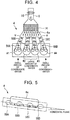
- FIG. 4 is a view showing an exemplary relationship between the shape of the intake manifold 6a leading to the intake ports 58 (58A, 58B, 58C, and 58D) and the amounts of condensate water flowing to the respective cylinders.
- the intake manifold 6a shown in FIG. 4 has a symmetrical shape.
- An intake path from the intercooler 14 to the first cylinder #1 and an intake path from the intercooler 14 to the fourth cylinder #4 are symmetrical to each other.
- An intake path from the intercooler 14 to the second cylinder #2 and an intake path from the intercooler 14 to the third cylinder #3 are symmetrical to each other.
- the distance of the intake paths from the intercooler 14 to the second cylinder #2 and the third cylinder #3 is shorter than the distance of the intake paths from the intercooler 14 to the first cylinder #1 and the fourth cylinder #4.
- Condensate water is larger in inertial mass than gas and flows along the wall surface. Therefore, the flowability of condensate water increases as the distance from the intercooler 14 shortens. Therefore, in the example shown in FIG. 4 , the amounts of condensate water flowing to the intake ports 58B and 58C of the second cylinder #2 and the third cylinder #3 at the center are large, and the amounts of condensate water flowing to the intake ports 58A and 58D of the first cylinder #1 and the fourth cylinder #4 at both ends are small.
- FIG. 6 is a view showing another exemplary relationship between the shape of the intake manifold 6a leading to the intake ports 58 (58A, 58B, 58C, and 58D) and the amounts of condensate water flowing to the respective cylinders.
- the intake manifold 6a shown in FIG. 6 assumes such a shape that the position of the intercooler 14 is eccentric toward the left side in the drawing.
- the distances of the intake paths from the intercooler 14 to the respective cylinders lengthen in the sequence of the first cylinder #1, the second cylinder #2, the third cylinder #3, and the fourth cylinder #4. Therefore, in the example shown in FIG.
- the amount of condensate water flowing to the intake port 58A of the first cylinder #1 with the shortest distance of the intake path from the intercooler 14 is the largest, and the amount of condensate water flowing to the intake port 58D of the fourth cylinder #4 with the longest distance of the intake path from the intercooler 14 is the smallest.
- the amount of condensate water produced at the port or flowing into the port differs among the cylinders.
- the ranks of the amounts of condensate water among the cylinders may change depending on the condition. Therefore, with a view to taking a measure against the freezing of condensate water, it is desirable to consider that the amount of condensate water differs among the cylinders, and that the differences in the amount of condensate water among the cylinders change depending on the condition.
- FIG. 7A is a view illustrating the influence of condensate water in an internal combustion engine to which the invention is not applied.
- the intake valve 62 is open during the stop of the engine, if the outside air temperature has fallen to a degree below freezing when the engine 2 is soaked (the temperature of the engine has fallen to the outside air temperature) after the stop of the engine 2, condensate water freezes in the gap between the valve face and valve seat of the intake valve 62. If the ice into which condensate water has frozen remains when the engine is started, a full-closure malfunction in the intake valve 62 resulting from the jamming by ice occurs, and compressed air leaks, in a compression stroke in which the intake valve 62 that has opened in a suction stroke closes again.
- FIG. 7B shows the operation in the case where the present embodiment of the invention is applied.
- the lift amount of the intake valve 62 is made equal to zero through the operation of the variable valve mechanism 66, and the intake valve 62 is stopped in that state.
- the operation of fully closing the intake valve 62 is not necessarily performed for all the cylinders.
- the operation of fully closing the intake valve 62 is performed only for that one of the cylinders (hereinafter referred to as a specific cylinder) in which the amount of condensate water produced in the intake port 58 or flowing into the intake port 58 after the stop of the engine is larger than in the other cylinders.
- a specific cylinder the amount of condensate water produced in the intake port 58 or flowing into the intake port 58 after the stop of the engine is larger than in the other cylinders.
- the second cylinder #2 and the third cylinder #3 may be treated as specific cylinders.
- the third cylinder #3 may be treated as a specific cylinder.
- only the first cylinder #1 may be treated as a specific cylinder, or the first cylinder #1 and the second cylinder #2 may be treated as specific cylinders.
- condensate water is prevented from freezing in the gap between the valve face and valve seat of the intake valve 62 when the engine 2 is soaked after being stopped, by fully closing and stopping the intake valve 62 in stopping the engine 2. Therefore, the full-closure malfunction in the intake valve 62 resulting from the jamming by ice does not occur when the engine is started.
- the air in the cylinders can be normally compressed in the compression stroke.
- Valve stop control is a program that is executed on a certain cycle by the electronic control unit 100.
- the control flow of this program is represented by a flowchart of FIG. 8 .
- valve stop control is constituted of six steps.
- the electronic control unit 100 determines whether or not an engine stop operation has been performed.
- the engine stop operation includes an operation that is performed by a driver to turn off an ignition switch of the engine 2, and an operation that is performed by the electronic control unit 100 to temporarily stop the engine 2 in an EV mode of the hybrid vehicle. If the engine stop operation has not been performed, there is no need to stop the valves 62 and 64, so the following processes are skipped.
- step S4 the electronic control unit 100 estimates an amount of condensate water in the intake system and an amount of condensate water in the exhaust system.
- an exhaust path from the exhaust valve 64 is divided into a plurality of circular rings in the direction opposite to the direction of flow, and a production amount of condensate water is calculated from a temperature of the wall surface and a dew-point temperature of exhaust gas for each of the circular rings. Then, this value is sequentially calculated from a downstream portion of the exhaust port 60 toward the exhaust valve 64.
- FIG. 9 is a flowchart showing the concrete calculation flow for calculating the amount of condensate water in the exhaust system.
- the electronic control unit 100 calculates the amount of condensate water in the exhaust system according to the calculation flow of FIG. 9 .
- a temperature of the wall surface at a position-n portion at the time when the exhaust path is divided into (n-MAX) circular rings is estimated (step S102).
- a dew-point temperature of exhaust gas at the position-n portion is calculated (step S104).
- an amount of change of condensate water at the position-n portion is calculated based on the temperature of the wall surface and the dew-point temperature (step S106).
- an outflow amount of condensate water flowing out from the position-n portion to an upstream region of the exhaust path is calculated (step S108), and an inflow amount of condensate water flowing from a downstream region of the exhaust path into the position-n portion is calculated (step S110).
- the amount of condensate water at the position-n portion is updated by adding the amount of change of condensate water, the outflow amount of condensate water, and the inflow amount of condensate water to a last value of the amount of condensate water at the position-n portion (step S112).
- a total amount of condensate water in the entire exhaust system is updated by adding the amount of condensate water at the position-n portion to the last value of the total amount of condensate water in the entire exhaust system (step S114).
- the value n is updated (step S116). Then, the processes from step 102 to step S116 are repeatedly executed until the value n exceeds a maximum value n-MAX (step S118).
- the intake path to the intake valve 62 is divided into a plurality of circular rings in the direction opposite to the direction of flow, and the production amount of condensate water is calculated from the temperature of the wall surface and the dew-point temperature of intake air for each of the circular rings. Then, this value is sequentially calculated from an upstream portion of the intake port 58 toward the intake valve 62. Specifically, the amount of condensate water in the intake system is calculated according to the calculation flow created in the same way of thinking as the method of calculating the amount of condensate water in the exhaust system.
- step S6 the electronic control unit 100 determines whether or not the amount of condensate water in the intake system estimated in step S4 is larger than a threshold.
- the threshold that is used in the determination of step S6 is an upper limit of the amount of condensate water that allows the intake valve 62 to be kept from being stopped in its fully-closed state. The freezing of condensate water in the gap between the valve face and the valve sheet does not occur when the amount of condensate water is small.
- step S6 if the result of the determination in step S6 is negative, namely, if the amount of condensate water is equal to or smaller than the threshold, the operation of stopping the intake valve 62 in its fully-closed state is not performed. Thus, the consumption of energy can be suppressed.
- step S6 the electronic control unit 100 performs the control of stopping the intake valve 62 as a specific valve in its fully-closed state in step S8.
- the stop of the intake valve 62 in its fully-closed state is realized by making the lift amount of the intake valve 62 equal to zero through the operation of the variable valve mechanism 66.
- the cylinder whose intake valve 62 is stopped in its fully-closed state is required to be that one of the cylinders in which it is determined that the amount of condensate water turns out in advance to be larger than in the other cylinders, namely, the specific cylinder.
- the intake valve 62 is not stopped in its fully-closed state.
- the probability of the occurrence of circumstances in which the intake valve 62 cannot be opened due to a malfunction in the variable valve mechanism 66 in restarting the engine can be lowered.
- the intake valve 62 accidentally stops in its fully-closed state in some cases due to a relationship with the crank angle at the time of the stop of the engine. As a matter of course, this accidental stop of the intake valve 62 in its fully-closed state is permitted.
- step S10 the electronic control unit 100 determines whether or not the amount of condensate water in the exhaust system estimated in step S4 is larger than a threshold.
- the threshold that is used in the determination of step S10 is an upper limit of the amount of condensate water that allows the exhaust valve 64 to be kept from being stopped in its fully-closed state. If the result of the determination in step S10 is negative, namely, if the amount of condensate water is equal to or smaller than the threshold, the operation of stopping the exhaust valve 64 in its fully-closed state is not performed. Thus, the consumption of energy can be suppressed.
- step S10 the electronic control unit 100 performs the control of stopping the exhaust valve 64 as a specific valve in its fully-closed state in step S12.
- the stop of the exhaust valve 64 in its fully-closed state is realized by making the lift amount of the exhaust valve 64 equal to zero through the operation of the variable valve mechanism 68.
- the cylinder in which the exhaust valve 64 is stopped in its fully-closed state is required to be the specific cylinder in which the amount of condensate water turns out in advance to be larger than in the other cylinders.
- the probability of the occurrence of circumstances where the exhaust valve 64 cannot be opened due to a malfunction in the variable valve mechanism 68 in restarting the engine can be lowered.
- the exhaust valve 64 accidentally stops in its fully-closed state in some cases due to a relationship with the crank angle at the time of the stop of the engine. As a matter of course, this accidental stop of the exhaust valve 64 in its fully-closed state is permitted.
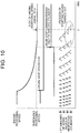
- FIG. 10 is a view showing the timing for starting valve stop after the operation of stopping the engine.
- each of the second cylinder #2 and the fourth cylinder #4 is the specific cylinder in which the intake valve 62 is stopped in its fully-closed state.
- the second cylinder #2 and the fourth cylinder #4 are in a suction stroke at the time point when the engine 2 is stopped.
- the intake valve 62 is fully closed with the lift amount thereof made equal to zero. Therefore, when the engine 2 is in its soaked state after being stopped, condensate water is prevented from freezing in the gap between the valve face and valve seat of the intake valve 62.
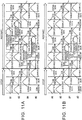
- FIG. 11A is a view showing the operation in restarting the engine in the case where the lift amount of the intake valve 62 is made equal to zero as to all the cylinders #1 to #4 when the engine is stopped.
- FIG. 11B is a view showing the operation in restarting the engine in the case where the lift amount of only the intake valve 62 in each of the specific cylinders #2 and #4 is made equal to zero when the engine is stopped.
- the lift amount of the intake valve 62 is made equal to zero by operating the variable valve mechanism 66
- a changeover period of at least one cycle is needed for each of the cylinders in order to return the lift amount of the intake valve 62 to its original value by operating the variable valve mechanism 66 again.
- FIG. 11A and FIG. 11B only the intake valve 62 in each of the specific cylinders #2 and #4 is stopped in its fully-closed state when the engine is stopped.
- the time needed to restart the engine 2 can be shortened.
- the specific valve is the intake valve 62
- the specific cylinder when the specific cylinder first enters a suction stroke in restarting the engine, initial explosion cannot be carried out because the intake valve 62 is fully closed. Therefore, initial explosion is awaited until another one of the cylinders subsequently enters a suction stroke, so it takes a long time to start the engine. Therefore, in making the lift amount of the intake valve 62 as the specific valve equal to zero, the electronic control unit 100 controls the stop crank angle of the engine 2 such that one of the cylinders other than the specific cylinder first enters a suction stroke in starting the engine next time.
- the electronic control unit 100 controls the stop crank angle of the engine 2 by, for example, stop position control means such as a starting motor, a motor for driving a hybrid vehicle, or the like, such that the engine 2 is stopped immediately before the intake valve 62 in the cylinder that enters the suction stroke subsequently to the specific cylinder is lifted.
- stop position control means such as a starting motor, a motor for driving a hybrid vehicle, or the like
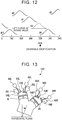
- FIG. 12 is a view showing an example of the stop crank angle of the engine 2 in the case where valve stop control is performed.
- the third cylinder #3 is a specific cylinder, and the engine 2 is stopped at a crank angle at which the third cylinder #3 enters a suction stroke. Specifically, the engine 2 is stopped immediately before the intake valve 62 in the fourth cylinder #4 that enters the suction stroke subsequently to the third cylinder #3 is lifted.
- the intake valve 62 in the fourth cylinder #4 opens, so the cylinder in which initial explosion is carried out shifts to the second cylinder #2, and the time for restarting the engine is extended by a rotational angle of 180°.
- the invention is also applicable to a V-engine that is transversely mounted on an FF vehicle.
- An engine 102 shown in FIG. 13 is transversely mounted on a front portion of the vehicle while being inclined in a rotational direction of the crankshaft.
- the engine 102 has two banks 4R and 4L.
- the right bank 4R is located on a front side of the vehicle, and the left bank 4L is located on a rear side of the vehicle.
- the bank angle between the right bank 4R and the left bank 4L is equal to 60°.
- Each of cylinder heads of the banks 4R and 4L is provided, for each of cylinders, with each of intake ports 58R and 58L and each of exhaust ports 60R and 60L, which lead to each of combustion chambers 56R and 56L in each of the cylinders.
- each of the intake ports 58R and 58L is provided inside the engine 102, and each of the exhaust ports 60R and 60L is provided outside the engine 102.
- a space between each of the combustion chambers 56R and 56L and each of the intake ports 58R and 58L is opened/closed by each of intake valves 62R and 62L.
- a space between each of the combustion chambers 56R and 56L and each of the exhaust ports 60R and 60L is opened/closed by each of exhaust valves 64R and 64L.
- the intake valves 62R and 62L and the exhaust valves 64R and 64L are all driven by mechanical variable valve mechanisms 66R, 66L, 68R, and 68L respectively.
- the intake port 58R in the right bank 4R is more vertically erected than the intake port 58L in the left bank 4L, so condensate water is more likely to accumulate around the intake valve 62R in the right bank 4R.
- the exhaust port 60L in the left bank 4L is more vertically erected than the exhaust port 60R in the right bank 4R, so condensate water is more likely to accumulate around the exhaust valve 64L of the left bank 4L.
- the cylinder that is provided in the bank in which condensate water is likely to accumulate around the valve is regarded as a specific cylinder. That is, in the case where the intake valve is a specific valve, one of the cylinders in the right bank 4R is regarded as a specific cylinder. When the engine is stopped, the intake valve 62R in that cylinder in the right bank 4R is stopped in its fully-closed state. Besides, in the case where the exhaust valve is a specific valve, one of the cylinders in the left bank 4L is regarded as a specific cylinder.
- variable valve mechanism is mechanically operated, but may be electrically operated.
- the electrically operated variable valve mechanism that directly drives the valves by an electromagnetic coil or a motor can perform the operation of opening/closing the valves in an operation of preventing freezing without rotating the engine.
- the cylinders that are regarded as specific cylinders are fixed in advance.
- the specific cylinder or specific cylinders may be determined again every time the engine is stopped.
- the amount of condensate water in the intake port or the exhaust port may be estimated for each of the cylinders, and the cylinder in which the amount of condensate water is larger than in the other cylinders may be determined as a specific cylinder.
- the cylinder having a port with the largest amount of condensate water in both the intake system and the exhaust system may be determined as a specific cylinder, and the valve corresponding to the port may be determined as a specific valve.
Landscapes
- Engineering & Computer Science (AREA)
- Mechanical Engineering (AREA)
- General Engineering & Computer Science (AREA)
- Chemical & Material Sciences (AREA)
- Combustion & Propulsion (AREA)
- Physics & Mathematics (AREA)
- Electromagnetism (AREA)
- Thermal Sciences (AREA)
- Output Control And Ontrol Of Special Type Engine (AREA)
- Combined Controls Of Internal Combustion Engines (AREA)
- Supercharger (AREA)
- Exhaust-Gas Circulating Devices (AREA)
Abstract

Description
- The invention relates to a control apparatus and control method for an internal combustion engine.
- In Japanese Patent Application Publication No.
2008-088835 JP 2008-088835 A - The invention provides a control apparatus and control method for an internal combustion engine that can restrain a full-closure malfunction in an intake valve or an exhaust valve from occurring through the freezing of condensate water in a gap between a valve face and valve seat of the valve after the stop of the internal combustion engine.
- A first aspect of the invention is a control apparatus for an internal combustion engine. The internal combustion engine includes a plurality of cylinders and ports. The ports include intake ports and exhaust ports corresponding to the plurality of the cylinders respectively. The internal combustion engine is an internal combustion engine in which amounts of condensate water produced in the ports or flowing into the ports are different from one another among the cylinders due to differences in shape or arrangement of the ports or conduits leading to the ports among the plurality of the cylinders as to either the intake ports or the exhaust ports. The control apparatus includes an electronic control unit. The electronic control unit is configured to perform an operation of making a lift amount of a specific valve corresponding to one of either the intake ports or the exhaust ports for a specific cylinder when the internal combustion engine is stopped, in a case where the electronic control unit predicts that condensate water is produced in one of either the intake ports or the exhaust ports or condensate water flows into one of either the intake ports or the exhaust ports. The specific cylinder is a cylinder in which an amount of condensate water produced in one of either the corresponding intake ports or the corresponding exhaust ports or condensate water flowing into one of either the corresponding intake ports or the corresponding exhaust ports is larger than in the other ones of the plurality of the cylinders.
- When the lift amount of the valve is equal to zero, namely, when the valve is completely closed, there is no gap created between a valve face and a valve seat, so no condensate water accumulates therebetween. By performing this operation for the specific valve in the specific cylinder in which the amount of condensate water is larger than in the other cylinders, a full-closure malfunction in the valve can be prevented from occurring due to the freezing of condensate water in the gap between the valve face and the valve seat in the specific cylinder. Also, in the entire internal combustion engine, the occurrence of such a full-closure malfunction can be suppressed.
- It can be estimated whether or not condensate water is produced in the port or flows into the port, for example, from an operating condition and external environmental condition of the internal combustion engine. An elapsed time from the stop of the internal combustion engine may also be used as a piece of information for determining whether or not condensate water flows into the port. It should be noted, however, that a problem of the freezing of condensate water in the gap between the valve face and the valve seat does not arise when the amount of condensate water is small. Therefore, the amount of condensate water in the entire engine may be estimated as to the respective ports, and the operation of making the lift amount of the specific valve equal to zero when the engine is stopped may be performed only in the case where the estimated amount of condensate water is larger than a predetermined threshold. That is, even in the case where the production of condensate water in the port or the inflow of condensate water into the port is predicted, there is no need to perform the aforementioned operation when the estimated amount of condensate water is equal to or smaller than the threshold. Thus, the consumption of energy can be suppressed.
- The cylinder regarded as the specific cylinder may be fixed in advance, or may be determined each time. For example, the amounts of condensate water in either the intake ports or the exhaust ports may be estimated individually for the cylinders, and the cylinder in which the amount of condensate water is larger than in the other cylinders may be determined as the specific cylinder. Incidentally, it is not indispensable to determine only one of the cylinders as the specific cylinder. A plurality of the cylinders may be regarded as specific cylinders. For example, the cylinders constituting the internal combustion engine may be divided into a group with a relatively large amount of condensate water and a group with a relatively small amount of condensate water, and all the cylinders belonging to the group with the relatively large amount of condensate water may be regarded as specific cylinders.
- The internal combustion engine may include an exhaust gas recirculation (EGR) device that recirculates part of exhaust gas to an intake passage. The ports in which condensate water is produced or into which condensate water flows may be the intake ports, and the specific valve may be an intake valve. When the internal combustion engine includes the EGR device, the production of condensate water or the inflow of condensate water occurs in the intake ports after the stop of the engine. Further, the internal combustion engine may include a compressor and an intercooler in the intake passage. Even in this case, the production of condensate water or the inflow of condensate water occurs in the intake ports after the stop of the engine. Thus, the ports in which condensate water is produced or into which condensate water flows may be the intake ports, and the specific valve may be an intake valve.
- The internal combustion engine may include a compressor and an intercooler in the intake passage. The either the intake ports or the exhaust ports may be the intake ports, and the specific valve may be the intake valve. The specific cylinder may be a cylinder in which an intake path from the intercooler to the intake valve is shorter than in the other cylinders. The likelihood of accumulation of condensate water in the cylinder increases as the intake passage from the intercooler to the intake valve shortens. Therefore, by regarding the intake valve in this cylinder as a specific valve, the occurrence of a full-closure malfunction in the valve can be suppressed.
- The specific cylinder may be a cylinder in which an intake path from a surge tank to the intake valve is shorter than in the other cylinders, and the specific valve may be the intake valve. The likelihood of accumulation of condensate water in the cylinder increases as the intake passage from the surge tank to the intake valve shortens. Therefore, by regarding the intake valve in this cylinder as a specific valve, the occurrence of a full-closure malfunction in the valve can be suppressed.
- The internal combustion engine may be a V-engine that is mounted on a vehicle while being inclined in a rotational direction of a crankshaft. In this case, the specific cylinder may be a cylinder that is provided in that one of two banks constituting the V-engine in which an angle formed by a direction of connection of one of either the intake ports or the exhaust ports to a combustion chamber and a vertical direction is smaller than in the other bank. The likelihood of accumulation of condensate water around the valve after downward fall thereof along the port increases as the direction of connection of the port approaches the vertical direction. Therefore, by regarding such a cylinder as a specific cylinder, the occurrence of a full-closure malfunction in the valve can be suppressed.
- In the control apparatus for the internal combustion engine, the electronic control unit may be configured to estimate amounts of condensate water in either the intake ports or the exhaust ports individually for the cylinders when the engine is stopped. The electronic control unit may be configured to determine the specific cylinder based on the amounts of condensate water in the respective cylinders.
- In the control apparatus for the internal combustion engine, the electronic control unit may be configured to estimate an amount of condensate water in the entire internal combustion engine as to the either the intake ports or the exhaust ports. The electronic control unit may be configured to perform an operation of making a lift amount of the specific valve equal to zero when the internal combustion engine is stopped, in a case where the estimated amount of condensate water is larger than a predetermined threshold. The electronic control unit may be configured not to perform the operation of making the lift amount of the specific valve equal to zero when the internal combustion engine is stopped, in a case where the estimated amount of condensate water is equal to or smaller than the threshold.
- When the lift amount of the specific valve is made equal to zero, the rotational speed of the internal combustion engine is restrained from falling because the pumping loss decreases. As a result, it takes a long time until the internal combustion engine is completely stopped. Accordingly, in the control apparatus for the internal combustion engine, the electronic control unit may be configured to perform the operation of making the lift amount of the specific valve equal to zero when the internal combustion engine is stopped, after a rotational speed of the internal combustion engine becomes equal to or lower than a predetermined rotational speed.
- Besides, in the case where the specific valve is an intake valve, when the specific valve first enters a suction stroke in starting the engine next time, initial explosion cannot be carried out due to full-closure of the intake valve, so it takes a long time until the engine is started. Accordingly, in the control apparatus for the internal combustion engine, the electronic control unit may be configured to control a stop crank angle of the internal combustion engine such that one of the cylinders other than the specific cylinder first enters a suction stroke in starting the engine next time, in a case where the specific valve is the intake valve and the operation of making the lift amount of the specific valve equal to zero is performed when the internal combustion engine is stopped.
- A second aspect of the invention is a control method for an internal combustion engine. The internal combustion engine includes a plurality of cylinders and ports. The ports include intake ports and exhaust ports corresponding to the plurality of the cylinders respectively. The internal combustion engine is an internal combustion engine in which amounts of condensate water produced in the ports or flowing into the ports are different from one another among the cylinders due to differences in shape or arrangement of the ports or conduits leading to the ports among the plurality of the cylinders as to either the intake ports or the exhaust ports. The control method includes performing, by an electronic control unit, an operation of making a lift amount of a specific valve corresponding to one of either the intake ports or the exhaust ports for a specific cylinder when the internal combustion engine is stopped, in a case where the electronic control unit predicts hat condensate water is produced in one of either the intake ports or the exhaust ports or condensate water flows into one of either the intake ports or the exhaust ports. The specific cylinder is a cylinder in which an amount of condensate water produced in one of either the corresponding intake ports or the corresponding exhaust ports or condensate water flowing into one of either the corresponding intake ports or the corresponding exhaust ports is larger than in the other ones of the plurality of the cylinders.
- As described above, the control apparatus and control method for the internal combustion engine according to the invention can reduce the possibility of the occurrence of a full-closure malfunction in the valve resulting from the freezing of condensate water in the gap between the valve face and the valve seat after the stop of the internal combustion engine.
- Features, advantages, and technical and industrial significance of exemplary embodiments of the invention will be described below with reference to the accompanying drawings, in which like numerals denote like elements, and wherein:
-
FIG. 1 is a view showing the configuration of an entire system of an internal combustion engine according to one of the embodiments of the invention; -
FIG. 2 is a view showing the configuration of an engine body of the internal combustion engine according to one of the embodiments of the invention; -
FIG. 3 is a chart summarizing an operating condition and external environmental condition on which condensate water is produced in an intake system and an exhaust system; -
FIG. 4 is a view showing an exemplary relationship between the shape of an intake manifold and the amounts of condensate water flowing to respective cylinders; -
FIG. 5 is a view taken along a line V-V ofFIG. 4 , and is a view showing a relationship between the gradient of the engine body and the amounts of condensate water flowing to the respective cylinders; -
FIG. 6 is a view showing another exemplary relationship between the shape of the intake manifold and the amounts of condensate water flowing to the respective cylinders; -
FIG. 7A is a view illustrating the influence of condensate water that is produced when the invention is not applied; -
FIG. 7B is a view illustrating the operation of one of the embodiments of the invention; -
FIG. 8 is a flowchart showing the control flow of valve stop control; -
FIG. 9 is a flowchart showing the calculation flow for calculating the amount of condensate water; -
FIG. 10 is a view showing timings for starting the process of stopping valves; -
FIG. 11A is a view showing the operation at the time of restart in the case where the valves in all the cylinders are stopped; -
FIG. 11B is a view showing the operation at the time of restart in the case where only the valves in a required one or required ones of the cylinders are stopped; -
FIG. 12 is a view showing a stop crank angle of the internal combustion engine in the case where valve stop control is performed; and -
FIG. 13 is a view showing the configuration of a V-engine that is transversely mounted on an FF vehicle. - The embodiments of the invention will be described hereinafter with reference to the drawings. It should be noted, however, that each of the embodiments of the invention shown below exemplifies an apparatus and method for embodying the technical concept of the invention, and is not intended to limit the structure and arrangement of components, the sequence of processes and the like to those described below, unless otherwise specified. The invention is not limited to the embodiments thereof described below, but can be carried out after being modified in various manners within such a range as not to depart from the gist of the invention.
-
FIG. 1 is a view showing the configuration of an entire system of aninternal combustion engine 2 according to one of the embodiments of the invention. Thisinternal combustion engine 2 is an internal combustion engine (hereinafter referred to simply as an engine) that is mounted on a vehicle. Theengine 2 is constituted of anengine body 4, an intake system device including anintake passage 6, an exhaust system device including an exhaust passage 8, and an electronic control unit (ECU) 100. Acompressor 20a, athrottle 16, and anintercooler 14 are arranged in this order, from an upstream side toward theengine body 4, in theintake passage 6 through which air is introduced into theengine body 4 from the outside. Theintercooler 14 is integrated with a surge tank of anintake manifold 6a. Aturbine 20b that is combined with thecompressor 20a to constitute aturbo supercharger 20 is arranged in the exhaust passage 8 from which exhaust gas is discharged to the outside from theengine body 4. - The
internal combustion engine 2 is equipped with two exhaust gas recirculation (EGR)devices intake passage 6 from the exhaust passage 8. One of the EGR devices is the high-pressure-loop (HPL)-EGR device 30, and the other is the low-pressure-loop (LPL)-EGR device 40. The HPL-EGR device 30 is constituted of anEGR passage 32, anEGR cooler 36, and anEGR valve 34. TheEGR passage 32 connects theintake passage 6 downstream of thethrottle 16, for example, the surge tank or anintake port 58 to the exhaust passage 8 upstream of theturbine 20b. The LPL-EGR device 40 is constituted of anEGR passage 42, anEGR cooler 46, and anEGR valve 44. TheEGR passage 42 connects theintake passage 6 upstream of thecompressor 20a to the exhaust passage 8 downstream of theturbine 20b. - The
electronic control unit 100 has at least one processor and at least one memory. Various data including various programs and maps for controlling theengine 2 are stored in the memory. Various functions are realized in theelectronic control unit 100 through the loading of the programs stored in the memory and the execution thereof by the at least one processor. Various pieces of information on an operating state and operating condition of theengine 2 are input to theelectronic control unit 100 from various sensors attached to theengine 2 and the vehicle. Theelectronic control unit 100 determines, based on at least these pieces of information, operation amounts of actuators relevant to the operation of theengine 2. These actuators include a motor (not shown) (e.g., a starting motor or a driving motor for a hybrid vehicle) capable of forcibly rotating theengine body 4. Incidentally, theelectronic control unit 100 may be constituted of a plurality of ECU's. -
FIG. 2 is a view showing the configuration of theengine body 4. Theengine body 4 is configured as a multi-cylinder engine that is equipped with a plurality of cylinders, for example, an in-line four-cylinder engine. It should be noted, however, that theengine body 4 may be configured as a spark ignition-type engine or a diesel engine. A cylinder head of theengine body 4 is provided, for each of cylinders, with anintake port 58 and anexhaust port 60, which lead to acombustion chamber 56 of each of the cylinders. A space between thecombustion chamber 56 and theintake port 58 is opened/closed by anintake valve 62, and a space between thecombustion chamber 56 and theexhaust port 60 is opened/closed by anexhaust valve 64. Theintake port 58 and theexhaust port 60 will be hereinafter simply referred to also comprehensively as ports in some cases. - Both a
valve mechanism 66 that drives theintake valve 62, and avalve mechanism 68 that drives theexhaust valve 64 are mechanical variable valve mechanisms to which a driving force is distributed from a crankshaft (not shown) of theengine body 4. Thevariable valve mechanisms intake valve 62 and theexhaust valve 64 variable, and can stop theintake valve 62 and theexhaust valve 64 by making the lift amounts thereof equal to zero respectively. Besides, both the intake-side and exhaust-sidevariable valve mechanisms variable valve mechanisms electronic control unit 100. - In the
engine 2 configured as described above, condensate water flows into theintake port 58 and theexhaust port 60 in some cases. When this condensate water that has flowed into theintake port 58 and theexhaust port 60 reaches theintake valve 62 and theexhaust valve 64 respectively, the condensate water accumulates on a valve head of each valve in its fully-closed state. The condensate water flows down into each of the cylinders from a gap between a valve face and valve seat of each valve with a large opening degree. In some cases, however, the condensate water may remain as drops of water in the gap between the valve face and the valve seat, depending on the amount of condensate water. Besides, the condensate water stays in the gap between the valve face and valve seat of each valve with a small opening degree, instead of flowing down therefrom. The condensate water that has remained around theintake valve 62 and theexhaust valve 64 freezes into ice when the temperature around theintake valve 62 and theexhaust valve 64 falls below zero. The ice into which the condensate water freezes around theintake valve 62 and theexhaust valve 64 influences the startability in restarting theengine 2. For example, when the condensate water freezes between the valve face and the valve seat, a full-closure malfunction, namely, a failure to completely close theintake valve 62 or theexhaust valve 64 occurs. -
FIG. 3 shows a result obtained by investigating where and on what conditions the above-mentioned condensate water is produced.FIG. 3 is a chart summarizing an operating condition and external environmental condition on which condensate water is produced, as to each of an intake system and an exhaust system. - The chart shown in
FIG. 3 reveals that the intake system has production regions of condensate water that are peculiar to a supercharging LPL system, and production regions of condensate water that are common to the supercharging LPL system and a supercharging HPL system. The supercharging LPL system is a system that is equipped with the compressor and the LPL-EGR device, and EGR gas is introduced upstream of the compressor. The supercharging HPL system is a system that is equipped with the compressor and the HPL-EGR device, and EGR gas is introduced downstream of the compressor, more specifically, into the surge tank or the intake port. Incidentally, even in a naturally aspirated engine that is not equipped with a compressor, EGR is introduced into a surge tank or an intake port. Therefore, the production regions and production condition of condensate water in the naturally aspirated engine may be considered to be the same as those of the supercharging HPL system. - One of the production regions of condensate water in the supercharging LPL system is the intercooler. It should be noted, however, that the intercooler is a water-cooled intercooler, and that the temperature of coolant for the intercooler is assumed to be an outside air temperature + 10°C. The engine coolant temperature is irrelevant to the production of condensate water in this region. As for the outside air temperature, when the outside air temperature is low, the temperature of coolant for the intercooler falls, so the production amount of condensate water increases. As for the humidity, when the humidity is high, the production amount of condensate water increases. As for the supercharging pressure, when the supercharging pressure is high, the production amount of condensate water increases. Besides, condensate water is produced when EGR is carried out.
- The other production region of condensate water in the supercharging LPL system is a wall surface of an intake duct. The intake duct mentioned herein means the intake passage from the compressor to the intercooler. The engine coolant temperature is also relevant to the production of condensate water in this region. As for the engine coolant temperature, when the engine coolant temperature is low, the production amount of condensate water increases due to a fall in the temperature of the wall surface resulting from heat transfer. As for the outside air temperature, when the outside air temperature is low, the production amount of condensate water increases due to an air-cooling effect. The humidity and the supercharging pressure are the same as those on the production condition of condensate water in the intercooler. Besides, condensate water is produced when EGR is carried out.
- One of the production regions of condensate water common to the supercharging LPL system and the supercharging HPL system is an EGR delivery portion, namely, a region where each EGR passage is connected to the intake passage. An operating condition and external environmental condition on which condensate water is produced in this region are the same as the production condition of condensate water on the wall surface of the intake duct of the supercharging LPL system. Besides, condensate water is produced when EGR is carried out.
- Another one of the production regions of condensate water common to the supercharging LPL system and the supercharging HPL system is a wall surface of the surge tank. It should be noted, however, that when EGR gas is introduced into the intake port instead of being introduced into the surge tank in the supercharging HPL system, no condensate water is produced in this region. As for the engine coolant temperature, when the engine coolant temperature is low, namely, when the temperature of the wall surface of the surge tank is low, condensate water is produced. The engine coolant temperature at which condensate water is produced is estimated to be about 40°C. This temperature is equivalent to the dew point of the air-fuel mixture whose EGR rate is 30%. The outside air temperature, the humidity and the supercharging pressure are the same as those on the production condition of condensate water on the wall surface of the intake duct of the supercharging LPL system. Besides, condensate water is produced when EGR is carried out.
- The other production region of condensate water common to the supercharging LPL system and the supercharging HPL system is the wall surface of the intake port. As for the engine coolant temperature, when the engine coolant temperature is low, namely, when the temperature of the wall surface of the intake port is low, condensate water is produced. The engine coolant temperature at which condensate water is produced is estimated to be about 40°C. The outside air temperature is not very relevant to the production of condensate water in this region. It should be noted, however, that the production amount of condensate water tends to decrease when the outside air temperature is low. The humidity and the supercharging pressure are the same as those on the production condition of condensate water in the supercharging LPL system. Besides, condensate water is produced when EGR is carried out.
- As for the exhaust system, the presence/absence of the EGR device, the presence/absence of supercharging, and the like are irrelevant to the system. The production regions of condensate water are wall surfaces of the exhaust port and an exhaust pipe. The temperature of a wall of the exhaust pipe is relevant to the production of condensate water in these regions. When the temperature of the wall of the exhaust pipe is low, condensate water is produced. That is, in the exhaust system, condensate water is likely to be produced at the time of cold start of the engine. The temperature of the wall of the exhaust pipe at which condensate water is produced is estimated to be about 60°C. This temperature is equivalent to the dew point of exhaust gas. The outside air temperature is not very relevant to the production of condensate water in these regions. It should be noted, however, that the production amount of condensate water tends to increase when the outside air temperature is low. Besides, the influence of the humidity on the production of condensate water is small, and the supercharging pressure is irrelevant to the production of condensate water. Whether or not EGR is carried out is also irrelevant to the production of condensate water.
- As described above, the amount of condensate water produced in the engine is determined by various operating conditions and external environmental conditions that are relevant to the production regions. Besides, it is apparent that the amount of condensate water flowing to the ports is not homogeneous among the cylinders in the case where attention is focused on the individual cylinders. This has something to do with the difference in the shape or arrangement of the ports and ducts leading to the ports among the cylinders.
-
FIG. 4 is a view showing an exemplary relationship between the shape of theintake manifold 6a leading to the intake ports 58 (58A, 58B, 58C, and 58D) and the amounts of condensate water flowing to the respective cylinders. Theintake manifold 6a shown inFIG. 4 has a symmetrical shape. An intake path from theintercooler 14 to thefirst cylinder # 1 and an intake path from theintercooler 14 to thefourth cylinder # 4 are symmetrical to each other. An intake path from theintercooler 14 to thesecond cylinder # 2 and an intake path from theintercooler 14 to thethird cylinder # 3 are symmetrical to each other. The distance of the intake paths from theintercooler 14 to thesecond cylinder # 2 and thethird cylinder # 3 is shorter than the distance of the intake paths from theintercooler 14 to thefirst cylinder # 1 and thefourth cylinder # 4. Condensate water is larger in inertial mass than gas and flows along the wall surface. Therefore, the flowability of condensate water increases as the distance from theintercooler 14 shortens. Therefore, in the example shown inFIG. 4 , the amounts of condensate water flowing to theintake ports second cylinder # 2 and thethird cylinder # 3 at the center are large, and the amounts of condensate water flowing to theintake ports first cylinder # 1 and thefourth cylinder # 4 at both ends are small. - It should be noted, however, that when the
engine body 4 is inclined with respect to a horizontal plane as shown inFIG. 5 , condensate water is likely to flow toward a low portion of theengine body 4 because there is no gas flow during the stop of the engine. Theengine body 4 can be inclined in this manner not only when theengine body 4 is mounted at a certain angle on the vehicle but also when the vehicle is parked on an inclined land. In the example shown inFIG. 5 , theengine body 4 is inclined with its right side in the drawing located low. As a result, condensate water is likely to flow toward the right intake ports, and concentrates in theintake port 58C of thethird cylinder # 3. In the case where the gradient of theengine body 4 is larger, condensate water can concentrate in theintake port 58D of thefourth cylinder # 4 at an end portion of theengine body 4. -
FIG. 6 is a view showing another exemplary relationship between the shape of theintake manifold 6a leading to the intake ports 58 (58A, 58B, 58C, and 58D) and the amounts of condensate water flowing to the respective cylinders. Theintake manifold 6a shown inFIG. 6 assumes such a shape that the position of theintercooler 14 is eccentric toward the left side in the drawing. In the example shown inFIG. 6 , the distances of the intake paths from theintercooler 14 to the respective cylinders lengthen in the sequence of thefirst cylinder # 1, thesecond cylinder # 2, thethird cylinder # 3, and thefourth cylinder # 4. Therefore, in the example shown inFIG. 6 , the amount of condensate water flowing to theintake port 58A of thefirst cylinder # 1 with the shortest distance of the intake path from theintercooler 14 is the largest, and the amount of condensate water flowing to theintake port 58D of thefourth cylinder # 4 with the longest distance of the intake path from theintercooler 14 is the smallest. - As described above, the amount of condensate water produced at the port or flowing into the port differs among the cylinders. Besides, the ranks of the amounts of condensate water among the cylinders may change depending on the condition. Therefore, with a view to taking a measure against the freezing of condensate water, it is desirable to consider that the amount of condensate water differs among the cylinders, and that the differences in the amount of condensate water among the cylinders change depending on the condition.
-
FIG. 7A is a view illustrating the influence of condensate water in an internal combustion engine to which the invention is not applied. In the case where theintake valve 62 is open during the stop of the engine, if the outside air temperature has fallen to a degree below freezing when theengine 2 is soaked (the temperature of the engine has fallen to the outside air temperature) after the stop of theengine 2, condensate water freezes in the gap between the valve face and valve seat of theintake valve 62. If the ice into which condensate water has frozen remains when the engine is started, a full-closure malfunction in theintake valve 62 resulting from the jamming by ice occurs, and compressed air leaks, in a compression stroke in which theintake valve 62 that has opened in a suction stroke closes again. - In contrast,
FIG. 7B shows the operation in the case where the present embodiment of the invention is applied. In the present embodiment of the invention, when theengine 2 is stopped, the lift amount of theintake valve 62 is made equal to zero through the operation of thevariable valve mechanism 66, and theintake valve 62 is stopped in that state. It should be noted, however, that the operation of fully closing theintake valve 62 is not necessarily performed for all the cylinders. The operation of fully closing theintake valve 62 is performed only for that one of the cylinders (hereinafter referred to as a specific cylinder) in which the amount of condensate water produced in theintake port 58 or flowing into theintake port 58 after the stop of the engine is larger than in the other cylinders. For example, in the example shown inFIG. 4 , thesecond cylinder # 2 and thethird cylinder # 3 may be treated as specific cylinders. In the example shown inFIG. 5 , only thethird cylinder # 3 may be treated as a specific cylinder. In the example shown inFIG. 6 , only thefirst cylinder # 1 may be treated as a specific cylinder, or thefirst cylinder # 1 and thesecond cylinder # 2 may be treated as specific cylinders. - According to the measure taken in the present embodiment of the invention, condensate water is prevented from freezing in the gap between the valve face and valve seat of the
intake valve 62 when theengine 2 is soaked after being stopped, by fully closing and stopping theintake valve 62 in stopping theengine 2. Therefore, the full-closure malfunction in theintake valve 62 resulting from the jamming by ice does not occur when the engine is started. Thus, the air in the cylinders can be normally compressed in the compression stroke. - The above-mentioned measure against the freezing of condensate water is taken in the form of valve stop control by the
electronic control unit 100. Valve stop control is a program that is executed on a certain cycle by theelectronic control unit 100. The control flow of this program is represented by a flowchart ofFIG. 8 . - As shown in the flowchart of
FIG. 8 , valve stop control is constituted of six steps. In step S2, theelectronic control unit 100 determines whether or not an engine stop operation has been performed. The engine stop operation includes an operation that is performed by a driver to turn off an ignition switch of theengine 2, and an operation that is performed by theelectronic control unit 100 to temporarily stop theengine 2 in an EV mode of the hybrid vehicle. If the engine stop operation has not been performed, there is no need to stop thevalves - In step S4, the
electronic control unit 100 estimates an amount of condensate water in the intake system and an amount of condensate water in the exhaust system. In estimating the amount of condensate water in the exhaust system, an exhaust path from theexhaust valve 64 is divided into a plurality of circular rings in the direction opposite to the direction of flow, and a production amount of condensate water is calculated from a temperature of the wall surface and a dew-point temperature of exhaust gas for each of the circular rings. Then, this value is sequentially calculated from a downstream portion of theexhaust port 60 toward theexhaust valve 64.FIG. 9 is a flowchart showing the concrete calculation flow for calculating the amount of condensate water in the exhaust system. In step S4, theelectronic control unit 100 calculates the amount of condensate water in the exhaust system according to the calculation flow ofFIG. 9 . - According to the calculation flow shown in
FIG. 9 , a temperature of the wall surface at a position-n portion at the time when the exhaust path is divided into (n-MAX) circular rings is estimated (step S102). Besides, a dew-point temperature of exhaust gas at the position-n portion is calculated (step S104). Subsequently, an amount of change of condensate water at the position-n portion is calculated based on the temperature of the wall surface and the dew-point temperature (step S106). Besides, an outflow amount of condensate water flowing out from the position-n portion to an upstream region of the exhaust path is calculated (step S108), and an inflow amount of condensate water flowing from a downstream region of the exhaust path into the position-n portion is calculated (step S110). Then, the amount of condensate water at the position-n portion is updated by adding the amount of change of condensate water, the outflow amount of condensate water, and the inflow amount of condensate water to a last value of the amount of condensate water at the position-n portion (step S112). Subsequently, a total amount of condensate water in the entire exhaust system is updated by adding the amount of condensate water at the position-n portion to the last value of the total amount of condensate water in the entire exhaust system (step S114). After the foregoing processes are ended, the value n is updated (step S116). Then, the processes fromstep 102 to step S116 are repeatedly executed until the value n exceeds a maximum value n-MAX (step S118). - In estimating the amount of condensate water in the intake system, the intake path to the
intake valve 62 is divided into a plurality of circular rings in the direction opposite to the direction of flow, and the production amount of condensate water is calculated from the temperature of the wall surface and the dew-point temperature of intake air for each of the circular rings. Then, this value is sequentially calculated from an upstream portion of theintake port 58 toward theintake valve 62. Specifically, the amount of condensate water in the intake system is calculated according to the calculation flow created in the same way of thinking as the method of calculating the amount of condensate water in the exhaust system. - Returning to
FIG. 8 again, the description of valve stop control will be continued. In step S6, theelectronic control unit 100 determines whether or not the amount of condensate water in the intake system estimated in step S4 is larger than a threshold. The threshold that is used in the determination of step S6 is an upper limit of the amount of condensate water that allows theintake valve 62 to be kept from being stopped in its fully-closed state. The freezing of condensate water in the gap between the valve face and the valve sheet does not occur when the amount of condensate water is small. Therefore, if the result of the determination in step S6 is negative, namely, if the amount of condensate water is equal to or smaller than the threshold, the operation of stopping theintake valve 62 in its fully-closed state is not performed. Thus, the consumption of energy can be suppressed. - If the result of the determination in step S6 is positive, the
electronic control unit 100 performs the control of stopping theintake valve 62 as a specific valve in its fully-closed state in step S8. The stop of theintake valve 62 in its fully-closed state is realized by making the lift amount of theintake valve 62 equal to zero through the operation of thevariable valve mechanism 66. The cylinder whoseintake valve 62 is stopped in its fully-closed state is required to be that one of the cylinders in which it is determined that the amount of condensate water turns out in advance to be larger than in the other cylinders, namely, the specific cylinder. That is, in the cylinder in which the freezing of condensate water in the gap between the valve face and the valve seat is unlikely to occur due to a small amount of condensate water, theintake valve 62 is not stopped in its fully-closed state. Thus, the probability of the occurrence of circumstances in which theintake valve 62 cannot be opened due to a malfunction in thevariable valve mechanism 66 in restarting the engine can be lowered. Incidentally, even in the cylinders other than the specific cylinder, theintake valve 62 accidentally stops in its fully-closed state in some cases due to a relationship with the crank angle at the time of the stop of the engine. As a matter of course, this accidental stop of theintake valve 62 in its fully-closed state is permitted. - In step S10, the
electronic control unit 100 determines whether or not the amount of condensate water in the exhaust system estimated in step S4 is larger than a threshold. The threshold that is used in the determination of step S10 is an upper limit of the amount of condensate water that allows theexhaust valve 64 to be kept from being stopped in its fully-closed state. If the result of the determination in step S10 is negative, namely, if the amount of condensate water is equal to or smaller than the threshold, the operation of stopping theexhaust valve 64 in its fully-closed state is not performed. Thus, the consumption of energy can be suppressed. - If the result of the determination in step S10 is positive, the
electronic control unit 100 performs the control of stopping theexhaust valve 64 as a specific valve in its fully-closed state in step S12. The stop of theexhaust valve 64 in its fully-closed state is realized by making the lift amount of theexhaust valve 64 equal to zero through the operation of thevariable valve mechanism 68. The cylinder in which theexhaust valve 64 is stopped in its fully-closed state is required to be the specific cylinder in which the amount of condensate water turns out in advance to be larger than in the other cylinders. Thus, the probability of the occurrence of circumstances where theexhaust valve 64 cannot be opened due to a malfunction in thevariable valve mechanism 68 in restarting the engine can be lowered. Incidentally, even in the cylinders other than the specific cylinder, theexhaust valve 64 accidentally stops in its fully-closed state in some cases due to a relationship with the crank angle at the time of the stop of the engine. As a matter of course, this accidental stop of theexhaust valve 64 in its fully-closed state is permitted. - Next, the timing for starting valve stop through valve stop control will be described.
FIG. 10 is a view showing the timing for starting valve stop after the operation of stopping the engine. When the lift amount of theintake valve 62 or theexhaust valve 64 is made equal to zero through valve stop control, the rotational speed of the engine is restrained from falling, due to a decrease in pumping loss, and it takes a long time until theengine 2 is completely stopped. Therefore, the operations of thevariable valve mechanisms - In the example shown in
FIG. 10 , each of thesecond cylinder # 2 and thefourth cylinder # 4 is the specific cylinder in which theintake valve 62 is stopped in its fully-closed state. In this example, thesecond cylinder # 2 and thefourth cylinder # 4 are in a suction stroke at the time point when theengine 2 is stopped. In each of these cylinders, theintake valve 62 is fully closed with the lift amount thereof made equal to zero. Therefore, when theengine 2 is in its soaked state after being stopped, condensate water is prevented from freezing in the gap between the valve face and valve seat of theintake valve 62. Incidentally, in this example, although theintake valve 62 in each of thefirst cylinder # 1 and thethird cylinder # 3 that are not the specific cylinders is also fully closed at the time point when theengine 2 is stopped, this is a coincidence resulting from a relationship with a stop crank angle. - In the case where the lift amount of the
intake valve 62 is made equal to zero only in each of the specific cylinders as in the present embodiment of the invention, there is also an advantage in that the time for restarting theengine 2 can be made shorter than in the case where the lift amount of theintake valve 62 is made equal to zero as to all the cylinders. This will be described usingFIG. 11 . -
FIG. 11A is a view showing the operation in restarting the engine in the case where the lift amount of theintake valve 62 is made equal to zero as to all thecylinders # 1 to #4 when the engine is stopped.FIG. 11B is a view showing the operation in restarting the engine in the case where the lift amount of only theintake valve 62 in each of thespecific cylinders # 2 and #4 is made equal to zero when the engine is stopped. In the case where the lift amount of theintake valve 62 is made equal to zero by operating thevariable valve mechanism 66, a changeover period of at least one cycle is needed for each of the cylinders in order to return the lift amount of theintake valve 62 to its original value by operating thevariable valve mechanism 66 again. As is apparent from a comparison betweenFIG. 11A and FIG. 11B , only theintake valve 62 in each of thespecific cylinders # 2 and #4 is stopped in its fully-closed state when the engine is stopped. Thus, the time needed to restart theengine 2 can be shortened. - By the way, in the case where the specific valve is the
intake valve 62, when the specific cylinder first enters a suction stroke in restarting the engine, initial explosion cannot be carried out because theintake valve 62 is fully closed. Therefore, initial explosion is awaited until another one of the cylinders subsequently enters a suction stroke, so it takes a long time to start the engine. Therefore, in making the lift amount of theintake valve 62 as the specific valve equal to zero, theelectronic control unit 100 controls the stop crank angle of theengine 2 such that one of the cylinders other than the specific cylinder first enters a suction stroke in starting the engine next time. More specifically, theelectronic control unit 100 controls the stop crank angle of theengine 2 by, for example, stop position control means such as a starting motor, a motor for driving a hybrid vehicle, or the like, such that theengine 2 is stopped immediately before theintake valve 62 in the cylinder that enters the suction stroke subsequently to the specific cylinder is lifted. -
FIG. 12 is a view showing an example of the stop crank angle of theengine 2 in the case where valve stop control is performed. In this example, thethird cylinder # 3 is a specific cylinder, and theengine 2 is stopped at a crank angle at which thethird cylinder # 3 enters a suction stroke. Specifically, theengine 2 is stopped immediately before theintake valve 62 in thefourth cylinder # 4 that enters the suction stroke subsequently to thethird cylinder # 3 is lifted. When the stop crank angle of theengine 2 is offset toward a retardation side from this desirable stop position, theintake valve 62 in thefourth cylinder # 4 opens, so the cylinder in which initial explosion is carried out shifts to thesecond cylinder # 2, and the time for restarting the engine is extended by a rotational angle of 180°. On the contrary, when the stop crank angle of theengine 2 is offset toward an advancement side from this desirable stop position, a rotational angle to the opening of theintake valve 62 in thefourth cylinder # 4 is needed in accordance with the amount of offset, so the time for restarting the engine is extended all the same. Therefore, the range from the crank angle at which theintake valve 62 in thefourth cylinder # 4 starts being lifted to the advancement side by a predetermined angle (e.g., 30°) is a desirable stop position as a crank angle at which theengine 2 is stopped. - Next, the other embodiments of the invention will be described. The invention is also applicable to a V-engine that is transversely mounted on an FF vehicle. An
engine 102 shown inFIG. 13 is transversely mounted on a front portion of the vehicle while being inclined in a rotational direction of the crankshaft. Theengine 102 has twobanks right bank 4R is located on a front side of the vehicle, and theleft bank 4L is located on a rear side of the vehicle. The bank angle between theright bank 4R and theleft bank 4L is equal to 60°. - Each of cylinder heads of the
banks intake ports exhaust ports combustion chambers banks intake ports engine 102, and each of theexhaust ports engine 102. A space between each of thecombustion chambers intake ports intake valves combustion chambers exhaust ports exhaust valves intake valves exhaust valves variable valve mechanisms - In the case of a V-engine that is mounted at a certain angle, while condensate water is likely to accumulate around a valve after flowing down through a port in one bank of the engine, there is no such likelihood in the other bank of the engine. The likelihood of the flow of condensate water is determined by an angle that is formed by a direction in which the port is connected to a combustion chamber and a vertical direction. As this angle decreases, the likelihood of flow of condensate water through the port increases, and the likelihood of accumulation of condensate water around the valve increases. In the example shown in
FIG. 13 , in an intake system, theintake port 58R in theright bank 4R is more vertically erected than theintake port 58L in theleft bank 4L, so condensate water is more likely to accumulate around theintake valve 62R in theright bank 4R. On the other hand, in an exhaust system, theexhaust port 60L in theleft bank 4L is more vertically erected than theexhaust port 60R in theright bank 4R, so condensate water is more likely to accumulate around theexhaust valve 64L of theleft bank 4L. - In the case where there is thus a difference in the likelihood of accumulation of condensate water between the banks, the cylinder that is provided in the bank in which condensate water is likely to accumulate around the valve is regarded as a specific cylinder. That is, in the case where the intake valve is a specific valve, one of the cylinders in the
right bank 4R is regarded as a specific cylinder. When the engine is stopped, theintake valve 62R in that cylinder in theright bank 4R is stopped in its fully-closed state. Besides, in the case where the exhaust valve is a specific valve, one of the cylinders in theleft bank 4L is regarded as a specific cylinder. When the engine is stopped, theexhaust valve 64L in that cylinder in theleft bank 4L is stopped in its fully-closed state. By regarding that one of the cylinders in which condensate water is likely to accumulate around the valve as a specific cylinder, the occurrence of a full-closure malfunction in the valve can be suppressed. - Incidentally, in the above-mentioned embodiment of the invention, the variable valve mechanism is mechanically operated, but may be electrically operated. The electrically operated variable valve mechanism that directly drives the valves by an electromagnetic coil or a motor can perform the operation of opening/closing the valves in an operation of preventing freezing without rotating the engine.
- Besides, in the above-mentioned embodiment of the invention, the cylinders that are regarded as specific cylinders are fixed in advance. However, the specific cylinder or specific cylinders may be determined again every time the engine is stopped. For example, the amount of condensate water in the intake port or the exhaust port may be estimated for each of the cylinders, and the cylinder in which the amount of condensate water is larger than in the other cylinders may be determined as a specific cylinder. Besides, the cylinder having a port with the largest amount of condensate water in both the intake system and the exhaust system may be determined as a specific cylinder, and the valve corresponding to the port may be determined as a specific valve.
Claims (11)
- A control apparatus for an internal combustion engine (2), the internal combustion engine (2) including a plurality of cylinders and ports, the ports including intake ports (58) and exhaust ports (60) corresponding to the plurality of the cylinders respectively, and the internal combustion engine (2) being an internal combustion engine in which amounts of condensate water produced in the ports or flowing into the ports are different from one another among the cylinders due to differences in shape or arrangement of the ports or conduits leading to the ports among the plurality of the cylinders as to either the intake ports (58) or the exhaust ports (60),
the control apparatus comprising
an electronic control unit (100) configured to perform an operation of making a lift amount of a specific valve corresponding to one of either the intake ports (58) or the exhaust ports (60) equal to zero for a specific cylinder when the internal combustion engine (2) is stopped, in a case where the electronic control unit (100) predicts that condensate water is produced in one of either the intake ports (58) or the exhaust ports (60) or condensate water flows into one of either the intake ports (58) or the exhaust ports (60), and the specific cylinder being a cylinder in which an amount of condensate water produced in one of either the corresponding intake ports (58) or the corresponding exhaust ports (60) or condensate water flowing into one of either the corresponding intake ports (58) or the corresponding exhaust ports (60) is larger than in the other ones of the plurality of the cylinders. - The control apparatus for the internal combustion engine (2) according to claim 1, wherein
the internal combustion engine (2) includes an exhaust gas recirculation device (30, 40) that recirculates part of exhaust gas to an intake passage (6),
the ports in which condensate water is produced or into which condensate water flows are the intake ports (58), and
the specific valve is an intake valve (62). - The control apparatus for the internal combustion engine (2) according to claim 1 or 2, wherein
the internal combustion engine (2) includes a compressor (20a) and an intercooler (14) in the intake passage (6),
the ports in which condensate water is produced or into which condensate water flows are the intake ports (58), and
the specific valve is the intake valve (62). - The control apparatus for the internal combustion engine (2) according to claim 3, wherein the specific cylinder is a cylinder in which an intake path from the intercooler (14) to the intake valve (62) is shorter than in the other cylinders.
- The control apparatus for the internal combustion engine (2) according to any one of claims 1 to 3, wherein
the specific cylinder is a cylinder in which an intake path from a surge tank to the intake valve (62) is shorter in the other cylinders, and
the specific valve is the intake valve (62). - The control apparatus for the internal combustion engine (2) according to any one of claims 1 to 5, wherein
the internal combustion engine (2) is a V-engine that is mounted on a vehicle while being inclined in a rotational direction of a crankshaft, and
the specific cylinder is a cylinder that is provided in that one of two banks constituting the V-engine in which an angle formed by a direction of connection of one of either the intake ports (58) and the exhaust ports (60) to a combustion chamber and a vertical direction is smaller than in the other bank. - The control apparatus for the internal combustion engine (2) according to any one of claims 1 to 6, wherein
the electronic control unit (100) is configured to estimate amounts of condensate water in either the intake ports (58) or the exhaust ports (60) individually for the cylinders when the engine is stopped, and
the electronic control unit (100) is configured to determine the specific cylinder based on amounts of condensate water in the respective cylinders. - The control apparatus for the internal combustion engine (2) according to any one of claims 1 to 7, wherein
the electronic control unit (100) is configured to estimate an amount of condensate water in the entire internal combustion engine as to the either the intake ports (58) or the exhaust ports (60),
the electronic control unit (100) is configured to perform the operation of making a lift amount of the specific valve equal to zero when the internal combustion engine is stopped, in a case where the estimated amount of condensate water is larger than a predetermined threshold, and
the electronic control unit (100) is configured not to perform the operation of making the lift amount of the specific valve equal to zero when the internal combustion engine is stopped, in a case where the estimated amount of condensate water is equal to or smaller than the threshold. - The control apparatus for the internal combustion engine (2) according to any one of claims 1 to 8, wherein
the electronic control unit (100) is configured to perform the operation of making the lift amount of the specific valve equal to zero when the internal combustion engine is stopped, after a rotational speed of the internal combustion engine becomes equal to or lower than a predetermined rotational speed. - The control apparatus for the internal combustion engine (2) according to any one of claims 1 to 9, wherein
the electronic control unit (100) is configured to control a stop crank angle of the internal combustion engine (2) such that one of the cylinders other than the specific cylinder first enters a suction stroke in starting the engine next time, when the specific valve is the intake valve (62) and the operation of making the lift amount of the specific valve equal to zero is performed when the internal combustion engine is stopped. - A control method for an internal combustion engine (2), the internal combustion engine (2) including a plurality of cylinders and ports, the ports including intake ports (58) and exhaust ports (60) corresponding to the plurality of the cylinders respectively, and the internal combustion engine (2) being an internal combustion engine in which amounts of condensate water produced in the ports or flowing into the ports are different from one another among the cylinders due to differences in shape or arrangement of the ports or conduits leading to the ports among the plurality of the cylinders as to either the intake ports (58) or the exhaust ports (60),
the control method comprising:
performing, by an electronic control unit (100), an operation of making a lift amount of a specific valve corresponding to one of either the intake ports (58) or the exhaust ports (60) for a specific cylinder when the internal combustion engine (2) is stopped, in a case where the electronic control unit (100) predicts that condensate water is produced in one of either the intake ports (58) or the exhaust ports (60) or condensate water flows into one of either the intake ports (58) or the exhaust ports (60), and the specific cylinder being a cylinder in which an amount of condensate water produced in one of either the corresponding intake ports (58) or the corresponding exhaust ports (60) or condensate water flowing into one of either the corresponding intake ports (58) or the corresponding exhaust ports (60) is larger than in the other ones of the plurality of the cylinders.
Applications Claiming Priority (1)
| Application Number | Priority Date | Filing Date | Title |
|---|---|---|---|
| JP2017056069A JP6589917B2 (en) | 2017-03-22 | 2017-03-22 | Control device for internal combustion engine |
Publications (2)
| Publication Number | Publication Date |
|---|---|
| EP3379059A1 true EP3379059A1 (en) | 2018-09-26 |
| EP3379059B1 EP3379059B1 (en) | 2020-02-26 |
Family
ID=61750049
Family Applications (1)
| Application Number | Title | Priority Date | Filing Date |
|---|---|---|---|
| EP18163362.9A Active EP3379059B1 (en) | 2017-03-22 | 2018-03-22 | Control apparatus for internal combustion engine and control method for internal combustion engine |
Country Status (4)
| Country | Link |
|---|---|
| US (1) | US10473040B2 (en) |
| EP (1) | EP3379059B1 (en) |
| JP (1) | JP6589917B2 (en) |
| CN (1) | CN108625997B (en) |
Families Citing this family (1)
| Publication number | Priority date | Publication date | Assignee | Title |
|---|---|---|---|---|
| DE102019202213B3 (en) * | 2019-02-19 | 2020-06-25 | Hitachi Automotive Systems, Ltd. | Method and device for predicting and avoiding condensation of moisture in an intake system of an internal combustion engine after engine shutdown |
Citations (9)
| Publication number | Priority date | Publication date | Assignee | Title |
|---|---|---|---|---|
| US20070017482A1 (en) * | 2005-07-19 | 2007-01-25 | Mitsubishi Denki Kabushiki Kaisha | Control apparatus of internal combustion engine |
| JP2008088835A (en) | 2006-09-29 | 2008-04-17 | Denso Corp | Control device for internal combustion engine |
| US20080098986A1 (en) * | 2006-10-31 | 2008-05-01 | Mckay Daniel L | ETC control system and method |
| EP2221464A1 (en) * | 2009-02-18 | 2010-08-25 | Toyota Jidosha Kabushiki Kaisha | Control unit for internal combustion engine |
| US20110196596A1 (en) * | 2010-02-08 | 2011-08-11 | Roland Schleser | Method and device for preventing water damage in internal combustion engines |
| US20150274153A1 (en) * | 2014-03-25 | 2015-10-01 | Toyota Jidosha Kabushiki Kaisha | Control apparatus for internal combustion engine |
| WO2016031113A1 (en) * | 2014-08-29 | 2016-03-03 | Toyota Jidosha Kabushiki Kaisha | Internal combustion engine |
| US20160082824A1 (en) * | 2013-04-15 | 2016-03-24 | Toyota Jidosha Kabushiki Kaisha | Control device for hybrid vehicles |
| GB2532092A (en) * | 2015-02-20 | 2016-05-11 | Ford Global Tech Llc | A method for preventing malfunctioning of a combined valve and aspirator assembly |
Family Cites Families (14)
| Publication number | Priority date | Publication date | Assignee | Title |
|---|---|---|---|---|
| JP2002266670A (en) | 2001-03-09 | 2002-09-18 | Denso Corp | Starting method of internal combustion engine for vehicle |
| US6725847B2 (en) * | 2002-04-10 | 2004-04-27 | Cummins, Inc. | Condensation protection AECD for an internal combustion engine employing cooled EGR |
| JP2007262956A (en) * | 2006-03-28 | 2007-10-11 | Toyota Motor Corp | Control device for internal combustion engine with egr device |
| DE102006036990A1 (en) * | 2006-08-08 | 2008-02-14 | Deutz Ag | Combination of an internal and an external exhaust gas recirculation |
| JP2009024685A (en) * | 2007-07-24 | 2009-02-05 | Toyota Motor Corp | Control device for internal combustion engine |
| US9169809B2 (en) * | 2012-08-20 | 2015-10-27 | Ford Global Technologies, Llc | Method for controlling a variable charge air cooler |
| JP2014105608A (en) * | 2012-11-26 | 2014-06-09 | Toyota Motor Corp | Control device for internal combustion engine |
| JP6011360B2 (en) * | 2013-01-15 | 2016-10-19 | 株式会社デンソー | Engine idle stop control device |
| US9127607B2 (en) * | 2013-05-29 | 2015-09-08 | Ford Global Technologies, Llc | Method for purging condensate from a charge air cooler |
| JP2016031057A (en) * | 2014-07-29 | 2016-03-07 | トヨタ自動車株式会社 | Internal combustion engine with turbocharger |
| US9988997B2 (en) * | 2014-10-22 | 2018-06-05 | Ford Global Technologies, Llc | Method and system for engine temperature control |
| US10323587B2 (en) * | 2016-11-02 | 2019-06-18 | Ford Global Technologies, Llc | Method and system for exhaust gas recirculation and heat recovery |
| JP6583339B2 (en) * | 2017-04-11 | 2019-10-02 | トヨタ自動車株式会社 | Control device for internal combustion engine |
| US10337426B2 (en) * | 2017-08-09 | 2019-07-02 | Ford Global Technologies, Llc | Methods and systems for reducing water accumulation in an engine |
-
2017
- 2017-03-22 JP JP2017056069A patent/JP6589917B2/en active Active
-
2018
- 2018-03-19 US US15/925,016 patent/US10473040B2/en not_active Expired - Fee Related
- 2018-03-20 CN CN201810229636.1A patent/CN108625997B/en not_active Expired - Fee Related
- 2018-03-22 EP EP18163362.9A patent/EP3379059B1/en active Active
Patent Citations (9)
| Publication number | Priority date | Publication date | Assignee | Title |
|---|---|---|---|---|
| US20070017482A1 (en) * | 2005-07-19 | 2007-01-25 | Mitsubishi Denki Kabushiki Kaisha | Control apparatus of internal combustion engine |
| JP2008088835A (en) | 2006-09-29 | 2008-04-17 | Denso Corp | Control device for internal combustion engine |
| US20080098986A1 (en) * | 2006-10-31 | 2008-05-01 | Mckay Daniel L | ETC control system and method |
| EP2221464A1 (en) * | 2009-02-18 | 2010-08-25 | Toyota Jidosha Kabushiki Kaisha | Control unit for internal combustion engine |
| US20110196596A1 (en) * | 2010-02-08 | 2011-08-11 | Roland Schleser | Method and device for preventing water damage in internal combustion engines |
| US20160082824A1 (en) * | 2013-04-15 | 2016-03-24 | Toyota Jidosha Kabushiki Kaisha | Control device for hybrid vehicles |
| US20150274153A1 (en) * | 2014-03-25 | 2015-10-01 | Toyota Jidosha Kabushiki Kaisha | Control apparatus for internal combustion engine |
| WO2016031113A1 (en) * | 2014-08-29 | 2016-03-03 | Toyota Jidosha Kabushiki Kaisha | Internal combustion engine |
| GB2532092A (en) * | 2015-02-20 | 2016-05-11 | Ford Global Tech Llc | A method for preventing malfunctioning of a combined valve and aspirator assembly |
Also Published As
| Publication number | Publication date |
|---|---|
| US10473040B2 (en) | 2019-11-12 |
| CN108625997B (en) | 2021-06-18 |
| EP3379059B1 (en) | 2020-02-26 |
| US20180274454A1 (en) | 2018-09-27 |
| JP2018159295A (en) | 2018-10-11 |
| CN108625997A (en) | 2018-10-09 |
| JP6589917B2 (en) | 2019-10-16 |
Similar Documents
| Publication | Publication Date | Title |
|---|---|---|
| US8511291B2 (en) | Positive crankcase ventilation system, cylinder head used for positive crankcase ventilation system, internal combustion engine including positive crankcase ventilation system, and positive crankcase ventilation method | |
| JP5527486B2 (en) | Ventilation control device for internal combustion engine | |
| EP2963263B1 (en) | Control device for internal combustion engine | |
| EP2888464B1 (en) | Control device and control method for internal combustion engine | |
| JP2015209782A (en) | Internal combustion engine | |
| US10012164B2 (en) | Control apparatus of engine | |
| EP3379059B1 (en) | Control apparatus for internal combustion engine and control method for internal combustion engine | |
| JP5796537B2 (en) | Control device for internal combustion engine | |
| JP5916403B2 (en) | Control device for internal combustion engine | |
| JP5737149B2 (en) | Vehicle control device | |
| US10436078B2 (en) | Control device for internal combustion engine | |
| JP7247955B2 (en) | engine device | |
| JP2012171565A (en) | Ram air adjusting device | |
| JP2015121156A (en) | Control device of internal combustion engine | |
| JP7276248B2 (en) | engine device | |
| JP3755308B2 (en) | In-cylinder injection type internal combustion engine control device | |
| JP2019100256A (en) | Internal combustion engine system | |
| JP2006183553A (en) | Control device for internal combustion engine | |
| JP2014101886A (en) | Control device of internal combustion engine | |
| JP2014114776A (en) | Control device for internal combustion engine | |
| JP2012007507A (en) | Blow-by gas reflux device | |
| JP2012107525A (en) | Recirculation control device of internal combustion engine |
Legal Events
| Date | Code | Title | Description |
|---|---|---|---|
| PUAI | Public reference made under article 153(3) epc to a published international application that has entered the european phase |
Free format text: ORIGINAL CODE: 0009012 |
|
| STAA | Information on the status of an ep patent application or granted ep patent |
Free format text: STATUS: REQUEST FOR EXAMINATION WAS MADE |
|
| 17P | Request for examination filed |
Effective date: 20180421 |
|
| AK | Designated contracting states |
Kind code of ref document: A1 Designated state(s): AL AT BE BG CH CY CZ DE DK EE ES FI FR GB GR HR HU IE IS IT LI LT LU LV MC MK MT NL NO PL PT RO RS SE SI SK SM TR |
|
| AX | Request for extension of the european patent |
Extension state: BA ME |
|
| RIC1 | Information provided on ipc code assigned before grant |
Ipc: F02D 41/04 20060101AFI20190731BHEP Ipc: F02D 41/06 20060101ALI20190731BHEP |
|
| GRAP | Despatch of communication of intention to grant a patent |
Free format text: ORIGINAL CODE: EPIDOSNIGR1 |
|
| STAA | Information on the status of an ep patent application or granted ep patent |
Free format text: STATUS: GRANT OF PATENT IS INTENDED |
|
| INTG | Intention to grant announced |
Effective date: 20190911 |
|
| GRAS | Grant fee paid |
Free format text: ORIGINAL CODE: EPIDOSNIGR3 |
|
| GRAA | (expected) grant |
Free format text: ORIGINAL CODE: 0009210 |
|
| STAA | Information on the status of an ep patent application or granted ep patent |
Free format text: STATUS: THE PATENT HAS BEEN GRANTED |
|
| AK | Designated contracting states |
Kind code of ref document: B1 Designated state(s): AL AT BE BG CH CY CZ DE DK EE ES FI FR GB GR HR HU IE IS IT LI LT LU LV MC MK MT NL NO PL PT RO RS SE SI SK SM TR |
|
| REG | Reference to a national code |
Ref country code: GB Ref legal event code: FG4D |
|
| REG | Reference to a national code |
Ref country code: CH Ref legal event code: EP |
|
| REG | Reference to a national code |
Ref country code: AT Ref legal event code: REF Ref document number: 1237913 Country of ref document: AT Kind code of ref document: T Effective date: 20200315 |
|
| REG | Reference to a national code |
Ref country code: IE Ref legal event code: FG4D |
|
| REG | Reference to a national code |
Ref country code: DE Ref legal event code: R096 Ref document number: 602018002601 Country of ref document: DE |
|
| PG25 | Lapsed in a contracting state [announced via postgrant information from national office to epo] |
Ref country code: RS Free format text: LAPSE BECAUSE OF FAILURE TO SUBMIT A TRANSLATION OF THE DESCRIPTION OR TO PAY THE FEE WITHIN THE PRESCRIBED TIME-LIMIT Effective date: 20200226 Ref country code: FI Free format text: LAPSE BECAUSE OF FAILURE TO SUBMIT A TRANSLATION OF THE DESCRIPTION OR TO PAY THE FEE WITHIN THE PRESCRIBED TIME-LIMIT Effective date: 20200226 Ref country code: NO Free format text: LAPSE BECAUSE OF FAILURE TO SUBMIT A TRANSLATION OF THE DESCRIPTION OR TO PAY THE FEE WITHIN THE PRESCRIBED TIME-LIMIT Effective date: 20200526 |
|
| REG | Reference to a national code |
Ref country code: NL Ref legal event code: MP Effective date: 20200226 |
|
| REG | Reference to a national code |
Ref country code: LT Ref legal event code: MG4D |
|
| PG25 | Lapsed in a contracting state [announced via postgrant information from national office to epo] |
Ref country code: LV Free format text: LAPSE BECAUSE OF FAILURE TO SUBMIT A TRANSLATION OF THE DESCRIPTION OR TO PAY THE FEE WITHIN THE PRESCRIBED TIME-LIMIT Effective date: 20200226 Ref country code: SE Free format text: LAPSE BECAUSE OF FAILURE TO SUBMIT A TRANSLATION OF THE DESCRIPTION OR TO PAY THE FEE WITHIN THE PRESCRIBED TIME-LIMIT Effective date: 20200226 Ref country code: BG Free format text: LAPSE BECAUSE OF FAILURE TO SUBMIT A TRANSLATION OF THE DESCRIPTION OR TO PAY THE FEE WITHIN THE PRESCRIBED TIME-LIMIT Effective date: 20200526 Ref country code: IS Free format text: LAPSE BECAUSE OF FAILURE TO SUBMIT A TRANSLATION OF THE DESCRIPTION OR TO PAY THE FEE WITHIN THE PRESCRIBED TIME-LIMIT Effective date: 20200626 Ref country code: GR Free format text: LAPSE BECAUSE OF FAILURE TO SUBMIT A TRANSLATION OF THE DESCRIPTION OR TO PAY THE FEE WITHIN THE PRESCRIBED TIME-LIMIT Effective date: 20200527 Ref country code: HR Free format text: LAPSE BECAUSE OF FAILURE TO SUBMIT A TRANSLATION OF THE DESCRIPTION OR TO PAY THE FEE WITHIN THE PRESCRIBED TIME-LIMIT Effective date: 20200226 |
|
| PG25 | Lapsed in a contracting state [announced via postgrant information from national office to epo] |
Ref country code: NL Free format text: LAPSE BECAUSE OF FAILURE TO SUBMIT A TRANSLATION OF THE DESCRIPTION OR TO PAY THE FEE WITHIN THE PRESCRIBED TIME-LIMIT Effective date: 20200226 |
|
| PG25 | Lapsed in a contracting state [announced via postgrant information from national office to epo] |
Ref country code: RO Free format text: LAPSE BECAUSE OF FAILURE TO SUBMIT A TRANSLATION OF THE DESCRIPTION OR TO PAY THE FEE WITHIN THE PRESCRIBED TIME-LIMIT Effective date: 20200226 Ref country code: SK Free format text: LAPSE BECAUSE OF FAILURE TO SUBMIT A TRANSLATION OF THE DESCRIPTION OR TO PAY THE FEE WITHIN THE PRESCRIBED TIME-LIMIT Effective date: 20200226 Ref country code: SM Free format text: LAPSE BECAUSE OF FAILURE TO SUBMIT A TRANSLATION OF THE DESCRIPTION OR TO PAY THE FEE WITHIN THE PRESCRIBED TIME-LIMIT Effective date: 20200226 Ref country code: PT Free format text: LAPSE BECAUSE OF FAILURE TO SUBMIT A TRANSLATION OF THE DESCRIPTION OR TO PAY THE FEE WITHIN THE PRESCRIBED TIME-LIMIT Effective date: 20200719 Ref country code: DK Free format text: LAPSE BECAUSE OF FAILURE TO SUBMIT A TRANSLATION OF THE DESCRIPTION OR TO PAY THE FEE WITHIN THE PRESCRIBED TIME-LIMIT Effective date: 20200226 Ref country code: EE Free format text: LAPSE BECAUSE OF FAILURE TO SUBMIT A TRANSLATION OF THE DESCRIPTION OR TO PAY THE FEE WITHIN THE PRESCRIBED TIME-LIMIT Effective date: 20200226 Ref country code: LT Free format text: LAPSE BECAUSE OF FAILURE TO SUBMIT A TRANSLATION OF THE DESCRIPTION OR TO PAY THE FEE WITHIN THE PRESCRIBED TIME-LIMIT Effective date: 20200226 Ref country code: CZ Free format text: LAPSE BECAUSE OF FAILURE TO SUBMIT A TRANSLATION OF THE DESCRIPTION OR TO PAY THE FEE WITHIN THE PRESCRIBED TIME-LIMIT Effective date: 20200226 Ref country code: ES Free format text: LAPSE BECAUSE OF FAILURE TO SUBMIT A TRANSLATION OF THE DESCRIPTION OR TO PAY THE FEE WITHIN THE PRESCRIBED TIME-LIMIT Effective date: 20200226 |
|
| REG | Reference to a national code |
Ref country code: AT Ref legal event code: MK05 Ref document number: 1237913 Country of ref document: AT Kind code of ref document: T Effective date: 20200226 |
|
| REG | Reference to a national code |
Ref country code: DE Ref legal event code: R097 Ref document number: 602018002601 Country of ref document: DE |
|
| PG25 | Lapsed in a contracting state [announced via postgrant information from national office to epo] |
Ref country code: MC Free format text: LAPSE BECAUSE OF FAILURE TO SUBMIT A TRANSLATION OF THE DESCRIPTION OR TO PAY THE FEE WITHIN THE PRESCRIBED TIME-LIMIT Effective date: 20200226 |
|
| REG | Reference to a national code |
Ref country code: BE Ref legal event code: MM Effective date: 20200331 |
|
| PG25 | Lapsed in a contracting state [announced via postgrant information from national office to epo] |
Ref country code: LU Free format text: LAPSE BECAUSE OF NON-PAYMENT OF DUE FEES Effective date: 20200322 |
|
| PLBE | No opposition filed within time limit |
Free format text: ORIGINAL CODE: 0009261 |
|
| STAA | Information on the status of an ep patent application or granted ep patent |
Free format text: STATUS: NO OPPOSITION FILED WITHIN TIME LIMIT |
|
| PG25 | Lapsed in a contracting state [announced via postgrant information from national office to epo] |
Ref country code: AT Free format text: LAPSE BECAUSE OF FAILURE TO SUBMIT A TRANSLATION OF THE DESCRIPTION OR TO PAY THE FEE WITHIN THE PRESCRIBED TIME-LIMIT Effective date: 20200226 Ref country code: IE Free format text: LAPSE BECAUSE OF NON-PAYMENT OF DUE FEES Effective date: 20200322 Ref country code: IT Free format text: LAPSE BECAUSE OF FAILURE TO SUBMIT A TRANSLATION OF THE DESCRIPTION OR TO PAY THE FEE WITHIN THE PRESCRIBED TIME-LIMIT Effective date: 20200226 |
|
| 26N | No opposition filed |
Effective date: 20201127 |
|
| PG25 | Lapsed in a contracting state [announced via postgrant information from national office to epo] |
Ref country code: SI Free format text: LAPSE BECAUSE OF FAILURE TO SUBMIT A TRANSLATION OF THE DESCRIPTION OR TO PAY THE FEE WITHIN THE PRESCRIBED TIME-LIMIT Effective date: 20200226 Ref country code: PL Free format text: LAPSE BECAUSE OF FAILURE TO SUBMIT A TRANSLATION OF THE DESCRIPTION OR TO PAY THE FEE WITHIN THE PRESCRIBED TIME-LIMIT Effective date: 20200226 Ref country code: BE Free format text: LAPSE BECAUSE OF NON-PAYMENT OF DUE FEES Effective date: 20200331 |
|
| REG | Reference to a national code |
Ref country code: DE Ref legal event code: R084 Ref document number: 602018002601 Country of ref document: DE |
|
| REG | Reference to a national code |
Ref country code: GB Ref legal event code: 746 Effective date: 20210929 |
|
| REG | Reference to a national code |
Ref country code: CH Ref legal event code: PL |
|
| PG25 | Lapsed in a contracting state [announced via postgrant information from national office to epo] |
Ref country code: CH Free format text: LAPSE BECAUSE OF NON-PAYMENT OF DUE FEES Effective date: 20210331 Ref country code: LI Free format text: LAPSE BECAUSE OF NON-PAYMENT OF DUE FEES Effective date: 20210331 |
|
| PGFP | Annual fee paid to national office [announced via postgrant information from national office to epo] |
Ref country code: GB Payment date: 20220127 Year of fee payment: 5 Ref country code: DE Payment date: 20220203 Year of fee payment: 5 |
|
| PG25 | Lapsed in a contracting state [announced via postgrant information from national office to epo] |
Ref country code: TR Free format text: LAPSE BECAUSE OF FAILURE TO SUBMIT A TRANSLATION OF THE DESCRIPTION OR TO PAY THE FEE WITHIN THE PRESCRIBED TIME-LIMIT Effective date: 20200226 Ref country code: MT Free format text: LAPSE BECAUSE OF FAILURE TO SUBMIT A TRANSLATION OF THE DESCRIPTION OR TO PAY THE FEE WITHIN THE PRESCRIBED TIME-LIMIT Effective date: 20200226 Ref country code: CY Free format text: LAPSE BECAUSE OF FAILURE TO SUBMIT A TRANSLATION OF THE DESCRIPTION OR TO PAY THE FEE WITHIN THE PRESCRIBED TIME-LIMIT Effective date: 20200226 |
|
| PGFP | Annual fee paid to national office [announced via postgrant information from national office to epo] |
Ref country code: FR Payment date: 20220209 Year of fee payment: 5 |
|
| PG25 | Lapsed in a contracting state [announced via postgrant information from national office to epo] |
Ref country code: MK Free format text: LAPSE BECAUSE OF FAILURE TO SUBMIT A TRANSLATION OF THE DESCRIPTION OR TO PAY THE FEE WITHIN THE PRESCRIBED TIME-LIMIT Effective date: 20200226 Ref country code: AL Free format text: LAPSE BECAUSE OF FAILURE TO SUBMIT A TRANSLATION OF THE DESCRIPTION OR TO PAY THE FEE WITHIN THE PRESCRIBED TIME-LIMIT Effective date: 20200226 |
|
| P01 | Opt-out of the competence of the unified patent court (upc) registered |
Effective date: 20230427 |
|
| REG | Reference to a national code |
Ref country code: DE Ref legal event code: R119 Ref document number: 602018002601 Country of ref document: DE |
|
| GBPC | Gb: european patent ceased through non-payment of renewal fee |
Effective date: 20230322 |
|
| PG25 | Lapsed in a contracting state [announced via postgrant information from national office to epo] |
Ref country code: GB Free format text: LAPSE BECAUSE OF NON-PAYMENT OF DUE FEES Effective date: 20230322 |
|
| PG25 | Lapsed in a contracting state [announced via postgrant information from national office to epo] |
Ref country code: GB Free format text: LAPSE BECAUSE OF NON-PAYMENT OF DUE FEES Effective date: 20230322 Ref country code: FR Free format text: LAPSE BECAUSE OF NON-PAYMENT OF DUE FEES Effective date: 20230331 Ref country code: DE Free format text: LAPSE BECAUSE OF NON-PAYMENT OF DUE FEES Effective date: 20231003 |