US20080098985A1 - Internal combustion engine system - Google Patents
Internal combustion engine system Download PDFInfo
- Publication number
- US20080098985A1 US20080098985A1 US11/976,833 US97683307A US2008098985A1 US 20080098985 A1 US20080098985 A1 US 20080098985A1 US 97683307 A US97683307 A US 97683307A US 2008098985 A1 US2008098985 A1 US 2008098985A1
- Authority
- US
- United States
- Prior art keywords
- internal combustion
- combustion engine
- heating medium
- ethanol
- heating
- Prior art date
- Legal status (The legal status is an assumption and is not a legal conclusion. Google has not performed a legal analysis and makes no representation as to the accuracy of the status listed.)
- Granted
Links
- 238000002485 combustion reaction Methods 0.000 title claims abstract description 171
- 238000010438 heat treatment Methods 0.000 claims abstract description 214
- LFQSCWFLJHTTHZ-UHFFFAOYSA-N Ethanol Chemical compound CCO LFQSCWFLJHTTHZ-UHFFFAOYSA-N 0.000 claims abstract description 204
- 238000002407 reforming Methods 0.000 claims abstract description 74
- RTZKZFJDLAIYFH-UHFFFAOYSA-N Diethyl ether Chemical compound CCOCC RTZKZFJDLAIYFH-UHFFFAOYSA-N 0.000 claims abstract description 63
- 239000000446 fuel Substances 0.000 claims abstract description 51
- 239000000203 mixture Substances 0.000 claims abstract description 49
- 239000002828 fuel tank Substances 0.000 claims abstract description 44
- 239000003502 gasoline Substances 0.000 claims abstract description 33
- 230000006835 compression Effects 0.000 claims abstract description 30
- 238000007906 compression Methods 0.000 claims abstract description 30
- IDGUHHHQCWSQLU-UHFFFAOYSA-N ethanol;hydrate Chemical compound O.CCO IDGUHHHQCWSQLU-UHFFFAOYSA-N 0.000 claims abstract description 22
- XLYOFNOQVPJJNP-UHFFFAOYSA-N water Substances O XLYOFNOQVPJJNP-UHFFFAOYSA-N 0.000 claims abstract description 16
- 239000003054 catalyst Substances 0.000 claims description 13
- DQYBDCGIPTYXML-UHFFFAOYSA-N ethoxyethane;hydrate Chemical compound O.CCOCC DQYBDCGIPTYXML-UHFFFAOYSA-N 0.000 claims description 10
- 239000000498 cooling water Substances 0.000 description 34
- AMXOYNBUYSYVKV-UHFFFAOYSA-M lithium bromide Chemical compound [Li+].[Br-] AMXOYNBUYSYVKV-UHFFFAOYSA-M 0.000 description 22
- 239000004215 Carbon black (E152) Substances 0.000 description 14
- 229930195733 hydrocarbon Natural products 0.000 description 14
- 150000002430 hydrocarbons Chemical class 0.000 description 14
- 239000007788 liquid Substances 0.000 description 14
- 238000010521 absorption reaction Methods 0.000 description 10
- 238000004378 air conditioning Methods 0.000 description 10
- 238000011144 upstream manufacturing Methods 0.000 description 9
- CURLTUGMZLYLDI-UHFFFAOYSA-N Carbon dioxide Chemical compound O=C=O CURLTUGMZLYLDI-UHFFFAOYSA-N 0.000 description 6
- 238000010586 diagram Methods 0.000 description 6
- OKTJSMMVPCPJKN-UHFFFAOYSA-N Carbon Chemical compound [C] OKTJSMMVPCPJKN-UHFFFAOYSA-N 0.000 description 3
- 229910052799 carbon Inorganic materials 0.000 description 3
- 229910002092 carbon dioxide Inorganic materials 0.000 description 3
- 239000001569 carbon dioxide Substances 0.000 description 3
- 238000001704 evaporation Methods 0.000 description 3
- 230000008020 evaporation Effects 0.000 description 2
- IPLONMMJNGTUAI-UHFFFAOYSA-M lithium;bromide;hydrate Chemical compound [Li+].O.[Br-] IPLONMMJNGTUAI-UHFFFAOYSA-M 0.000 description 2
- 230000007935 neutral effect Effects 0.000 description 2
- 230000005855 radiation Effects 0.000 description 2
- 238000010792 warming Methods 0.000 description 2
- QVGXLLKOCUKJST-UHFFFAOYSA-N atomic oxygen Chemical compound [O] QVGXLLKOCUKJST-UHFFFAOYSA-N 0.000 description 1
- 238000009835 boiling Methods 0.000 description 1
- 239000002826 coolant Substances 0.000 description 1
- 238000001816 cooling Methods 0.000 description 1
- 239000007789 gas Substances 0.000 description 1
- 238000005338 heat storage Methods 0.000 description 1
- 239000000463 material Substances 0.000 description 1
- 238000000034 method Methods 0.000 description 1
- 239000002480 mineral oil Substances 0.000 description 1
- TVMXDCGIABBOFY-UHFFFAOYSA-N octane Chemical compound CCCCCCCC TVMXDCGIABBOFY-UHFFFAOYSA-N 0.000 description 1
- 239000001301 oxygen Substances 0.000 description 1
- 229910052760 oxygen Inorganic materials 0.000 description 1
- 230000029553 photosynthesis Effects 0.000 description 1
- 238000010672 photosynthesis Methods 0.000 description 1
- 230000009467 reduction Effects 0.000 description 1
- 229920002545 silicone oil Polymers 0.000 description 1
Images


Classifications
-
- F—MECHANICAL ENGINEERING; LIGHTING; HEATING; WEAPONS; BLASTING
- F02—COMBUSTION ENGINES; HOT-GAS OR COMBUSTION-PRODUCT ENGINE PLANTS
- F02D—CONTROLLING COMBUSTION ENGINES
- F02D19/00—Controlling engines characterised by their use of non-liquid fuels, pluralities of fuels, or non-fuel substances added to the combustible mixtures
- F02D19/06—Controlling engines characterised by their use of non-liquid fuels, pluralities of fuels, or non-fuel substances added to the combustible mixtures peculiar to engines working with pluralities of fuels, e.g. alternatively with light and heavy fuel oil, other than engines indifferent to the fuel consumed
- F02D19/08—Controlling engines characterised by their use of non-liquid fuels, pluralities of fuels, or non-fuel substances added to the combustible mixtures peculiar to engines working with pluralities of fuels, e.g. alternatively with light and heavy fuel oil, other than engines indifferent to the fuel consumed simultaneously using pluralities of fuels
-
- F—MECHANICAL ENGINEERING; LIGHTING; HEATING; WEAPONS; BLASTING
- F02—COMBUSTION ENGINES; HOT-GAS OR COMBUSTION-PRODUCT ENGINE PLANTS
- F02D—CONTROLLING COMBUSTION ENGINES
- F02D19/00—Controlling engines characterised by their use of non-liquid fuels, pluralities of fuels, or non-fuel substances added to the combustible mixtures
- F02D19/06—Controlling engines characterised by their use of non-liquid fuels, pluralities of fuels, or non-fuel substances added to the combustible mixtures peculiar to engines working with pluralities of fuels, e.g. alternatively with light and heavy fuel oil, other than engines indifferent to the fuel consumed
- F02D19/0639—Controlling engines characterised by their use of non-liquid fuels, pluralities of fuels, or non-fuel substances added to the combustible mixtures peculiar to engines working with pluralities of fuels, e.g. alternatively with light and heavy fuel oil, other than engines indifferent to the fuel consumed characterised by the type of fuels
- F02D19/0649—Liquid fuels having different boiling temperatures, volatilities, densities, viscosities, cetane or octane numbers
- F02D19/0652—Biofuels, e.g. plant oils
- F02D19/0655—Biofuels, e.g. plant oils at least one fuel being an alcohol, e.g. ethanol
-
- F—MECHANICAL ENGINEERING; LIGHTING; HEATING; WEAPONS; BLASTING
- F02—COMBUSTION ENGINES; HOT-GAS OR COMBUSTION-PRODUCT ENGINE PLANTS
- F02D—CONTROLLING COMBUSTION ENGINES
- F02D19/00—Controlling engines characterised by their use of non-liquid fuels, pluralities of fuels, or non-fuel substances added to the combustible mixtures
- F02D19/06—Controlling engines characterised by their use of non-liquid fuels, pluralities of fuels, or non-fuel substances added to the combustible mixtures peculiar to engines working with pluralities of fuels, e.g. alternatively with light and heavy fuel oil, other than engines indifferent to the fuel consumed
- F02D19/0663—Details on the fuel supply system, e.g. tanks, valves, pipes, pumps, rails, injectors or mixers
- F02D19/0665—Tanks, e.g. multiple tanks
-
- F—MECHANICAL ENGINEERING; LIGHTING; HEATING; WEAPONS; BLASTING
- F02—COMBUSTION ENGINES; HOT-GAS OR COMBUSTION-PRODUCT ENGINE PLANTS
- F02D—CONTROLLING COMBUSTION ENGINES
- F02D19/00—Controlling engines characterised by their use of non-liquid fuels, pluralities of fuels, or non-fuel substances added to the combustible mixtures
- F02D19/06—Controlling engines characterised by their use of non-liquid fuels, pluralities of fuels, or non-fuel substances added to the combustible mixtures peculiar to engines working with pluralities of fuels, e.g. alternatively with light and heavy fuel oil, other than engines indifferent to the fuel consumed
- F02D19/0663—Details on the fuel supply system, e.g. tanks, valves, pipes, pumps, rails, injectors or mixers
- F02D19/0668—Treating or cleaning means; Fuel filters
- F02D19/0671—Means to generate or modify a fuel, e.g. reformers, electrolytic cells or membranes
-
- F—MECHANICAL ENGINEERING; LIGHTING; HEATING; WEAPONS; BLASTING
- F02—COMBUSTION ENGINES; HOT-GAS OR COMBUSTION-PRODUCT ENGINE PLANTS
- F02D—CONTROLLING COMBUSTION ENGINES
- F02D19/00—Controlling engines characterised by their use of non-liquid fuels, pluralities of fuels, or non-fuel substances added to the combustible mixtures
- F02D19/06—Controlling engines characterised by their use of non-liquid fuels, pluralities of fuels, or non-fuel substances added to the combustible mixtures peculiar to engines working with pluralities of fuels, e.g. alternatively with light and heavy fuel oil, other than engines indifferent to the fuel consumed
- F02D19/0663—Details on the fuel supply system, e.g. tanks, valves, pipes, pumps, rails, injectors or mixers
- F02D19/0686—Injectors
- F02D19/0692—Arrangement of multiple injectors per combustion chamber
-
- F—MECHANICAL ENGINEERING; LIGHTING; HEATING; WEAPONS; BLASTING
- F02—COMBUSTION ENGINES; HOT-GAS OR COMBUSTION-PRODUCT ENGINE PLANTS
- F02D—CONTROLLING COMBUSTION ENGINES
- F02D41/00—Electrical control of supply of combustible mixture or its constituents
- F02D41/0025—Controlling engines characterised by use of non-liquid fuels, pluralities of fuels, or non-fuel substances added to the combustible mixtures
-
- F—MECHANICAL ENGINEERING; LIGHTING; HEATING; WEAPONS; BLASTING
- F02—COMBUSTION ENGINES; HOT-GAS OR COMBUSTION-PRODUCT ENGINE PLANTS
- F02D—CONTROLLING COMBUSTION ENGINES
- F02D41/00—Electrical control of supply of combustible mixture or its constituents
- F02D41/30—Controlling fuel injection
- F02D41/3011—Controlling fuel injection according to or using specific or several modes of combustion
- F02D41/3017—Controlling fuel injection according to or using specific or several modes of combustion characterised by the mode(s) being used
- F02D41/3035—Controlling fuel injection according to or using specific or several modes of combustion characterised by the mode(s) being used a mode being the premixed charge compression-ignition mode
-
- F—MECHANICAL ENGINEERING; LIGHTING; HEATING; WEAPONS; BLASTING
- F02—COMBUSTION ENGINES; HOT-GAS OR COMBUSTION-PRODUCT ENGINE PLANTS
- F02M—SUPPLYING COMBUSTION ENGINES IN GENERAL WITH COMBUSTIBLE MIXTURES OR CONSTITUENTS THEREOF
- F02M25/00—Engine-pertinent apparatus for adding non-fuel substances or small quantities of secondary fuel to combustion-air, main fuel or fuel-air mixture
- F02M25/022—Adding fuel and water emulsion, water or steam
- F02M25/0221—Details of the water supply system, e.g. pumps or arrangement of valves
- F02M25/0224—Water treatment or cleaning
-
- F—MECHANICAL ENGINEERING; LIGHTING; HEATING; WEAPONS; BLASTING
- F02—COMBUSTION ENGINES; HOT-GAS OR COMBUSTION-PRODUCT ENGINE PLANTS
- F02M—SUPPLYING COMBUSTION ENGINES IN GENERAL WITH COMBUSTIBLE MIXTURES OR CONSTITUENTS THEREOF
- F02M25/00—Engine-pertinent apparatus for adding non-fuel substances or small quantities of secondary fuel to combustion-air, main fuel or fuel-air mixture
- F02M25/022—Adding fuel and water emulsion, water or steam
- F02M25/0228—Adding fuel and water emulsion
-
- F—MECHANICAL ENGINEERING; LIGHTING; HEATING; WEAPONS; BLASTING
- F02—COMBUSTION ENGINES; HOT-GAS OR COMBUSTION-PRODUCT ENGINE PLANTS
- F02M—SUPPLYING COMBUSTION ENGINES IN GENERAL WITH COMBUSTIBLE MIXTURES OR CONSTITUENTS THEREOF
- F02M25/00—Engine-pertinent apparatus for adding non-fuel substances or small quantities of secondary fuel to combustion-air, main fuel or fuel-air mixture
- F02M25/10—Engine-pertinent apparatus for adding non-fuel substances or small quantities of secondary fuel to combustion-air, main fuel or fuel-air mixture adding acetylene, non-waterborne hydrogen, non-airborne oxygen, or ozone
-
- F—MECHANICAL ENGINEERING; LIGHTING; HEATING; WEAPONS; BLASTING
- F02—COMBUSTION ENGINES; HOT-GAS OR COMBUSTION-PRODUCT ENGINE PLANTS
- F02B—INTERNAL-COMBUSTION PISTON ENGINES; COMBUSTION ENGINES IN GENERAL
- F02B1/00—Engines characterised by fuel-air mixture compression
- F02B1/12—Engines characterised by fuel-air mixture compression with compression ignition
-
- F—MECHANICAL ENGINEERING; LIGHTING; HEATING; WEAPONS; BLASTING
- F02—COMBUSTION ENGINES; HOT-GAS OR COMBUSTION-PRODUCT ENGINE PLANTS
- F02D—CONTROLLING COMBUSTION ENGINES
- F02D19/00—Controlling engines characterised by their use of non-liquid fuels, pluralities of fuels, or non-fuel substances added to the combustible mixtures
- F02D19/06—Controlling engines characterised by their use of non-liquid fuels, pluralities of fuels, or non-fuel substances added to the combustible mixtures peculiar to engines working with pluralities of fuels, e.g. alternatively with light and heavy fuel oil, other than engines indifferent to the fuel consumed
- F02D19/0626—Measuring or estimating parameters related to the fuel supply system
- F02D19/0628—Determining the fuel pressure, temperature or flow, the fuel tank fill level or a valve position
-
- F—MECHANICAL ENGINEERING; LIGHTING; HEATING; WEAPONS; BLASTING
- F02—COMBUSTION ENGINES; HOT-GAS OR COMBUSTION-PRODUCT ENGINE PLANTS
- F02D—CONTROLLING COMBUSTION ENGINES
- F02D19/00—Controlling engines characterised by their use of non-liquid fuels, pluralities of fuels, or non-fuel substances added to the combustible mixtures
- F02D19/06—Controlling engines characterised by their use of non-liquid fuels, pluralities of fuels, or non-fuel substances added to the combustible mixtures peculiar to engines working with pluralities of fuels, e.g. alternatively with light and heavy fuel oil, other than engines indifferent to the fuel consumed
- F02D19/0663—Details on the fuel supply system, e.g. tanks, valves, pipes, pumps, rails, injectors or mixers
- F02D19/0673—Valves; Pressure or flow regulators; Mixers
- F02D19/0678—Pressure or flow regulators therefor; Fuel metering valves therefor
-
- F—MECHANICAL ENGINEERING; LIGHTING; HEATING; WEAPONS; BLASTING
- F02—COMBUSTION ENGINES; HOT-GAS OR COMBUSTION-PRODUCT ENGINE PLANTS
- F02M—SUPPLYING COMBUSTION ENGINES IN GENERAL WITH COMBUSTIBLE MIXTURES OR CONSTITUENTS THEREOF
- F02M27/00—Apparatus for treating combustion-air, fuel, or fuel-air mixture, by catalysts, electric means, magnetism, rays, sound waves, or the like
- F02M27/02—Apparatus for treating combustion-air, fuel, or fuel-air mixture, by catalysts, electric means, magnetism, rays, sound waves, or the like by catalysts
-
- F—MECHANICAL ENGINEERING; LIGHTING; HEATING; WEAPONS; BLASTING
- F02—COMBUSTION ENGINES; HOT-GAS OR COMBUSTION-PRODUCT ENGINE PLANTS
- F02M—SUPPLYING COMBUSTION ENGINES IN GENERAL WITH COMBUSTIBLE MIXTURES OR CONSTITUENTS THEREOF
- F02M31/00—Apparatus for thermally treating combustion-air, fuel, or fuel-air mixture
- F02M31/02—Apparatus for thermally treating combustion-air, fuel, or fuel-air mixture for heating
- F02M31/16—Other apparatus for heating fuel
- F02M31/18—Other apparatus for heating fuel to vaporise fuel
-
- Y—GENERAL TAGGING OF NEW TECHNOLOGICAL DEVELOPMENTS; GENERAL TAGGING OF CROSS-SECTIONAL TECHNOLOGIES SPANNING OVER SEVERAL SECTIONS OF THE IPC; TECHNICAL SUBJECTS COVERED BY FORMER USPC CROSS-REFERENCE ART COLLECTIONS [XRACs] AND DIGESTS
- Y02—TECHNOLOGIES OR APPLICATIONS FOR MITIGATION OR ADAPTATION AGAINST CLIMATE CHANGE
- Y02T—CLIMATE CHANGE MITIGATION TECHNOLOGIES RELATED TO TRANSPORTATION
- Y02T10/00—Road transport of goods or passengers
- Y02T10/10—Internal combustion engine [ICE] based vehicles
- Y02T10/12—Improving ICE efficiencies
-
- Y—GENERAL TAGGING OF NEW TECHNOLOGICAL DEVELOPMENTS; GENERAL TAGGING OF CROSS-SECTIONAL TECHNOLOGIES SPANNING OVER SEVERAL SECTIONS OF THE IPC; TECHNICAL SUBJECTS COVERED BY FORMER USPC CROSS-REFERENCE ART COLLECTIONS [XRACs] AND DIGESTS
- Y02—TECHNOLOGIES OR APPLICATIONS FOR MITIGATION OR ADAPTATION AGAINST CLIMATE CHANGE
- Y02T—CLIMATE CHANGE MITIGATION TECHNOLOGIES RELATED TO TRANSPORTATION
- Y02T10/00—Road transport of goods or passengers
- Y02T10/10—Internal combustion engine [ICE] based vehicles
- Y02T10/30—Use of alternative fuels, e.g. biofuels
Definitions
- the present invention relates to an internal combustion engine system switchable between a spark ignition operation and a homogeneous charge compression ignition operation.
- homogeneous charge compression ignition internal combustion engines have problems that it is difficult to control ignition timing and the engines can be operated safely only in a narrow operating range. More specifically, the problems mean that use of a fuel with high ignitability tends to cause knocking when required load of the engine is high, and that use of a fuel with low ignitability tends to cause misfire when required load of the engine is low.
- an internal combustion engine system switchable between a spark ignition operation and a homogeneous charge compression ignition operation depending on operation conditions or the like for example, see Japanese Patent Laid-Open No. 2001-152919, and No. 2002-130006.
- two or more types of fuels having different ignition characteristics are prepared, and the mixture ratio of the fuels is controlled when the fuels are provided to the homogeneous charge compression ignition internal combustion engine, thereby controlling the ignition timing.
- the two or more types of fuels having different ignition characteristics may include a combination of liquid hydrocarbon such as gasoline or GTL naphtha and ethanol.
- ethanol allows the so-called “carbon neutral effect”, thereby contributing to carbon dioxide emission reductions.
- the carbon neutral effect means that combustion of ethanol derived from plants emits carbon dioxide but the net carbon emissions are zero because the material plants absorb carbon dioxide by carrying out photosynthesis in their growth processes.
- the liquid hydrocarbon and the ethanol may be contained in separate tanks.
- the liquid hydrocarbon and the ethanol may be contained as a mixed fuel in a single tank and separated into the liquid hydrocarbon and the ethanol as necessary. It is known that addition of water to the mixed fuel of liquid hydrocarbon and ethanol easily separates the fuel into the liquid hydrocarbon and an ethanol-water mixture (for example, see Japanese Patent Laid-Open No. 58-96155).
- an object of the present invention is to provide an internal combustion engine system switchable between a spark ignition operation and a homogeneous charge compression ignition operation in which the ignition timing of a homogeneous charge compression ignition can be controlled precisely during the homogeneous charge compression ignition operation.
- a first aspect of the internal combustion engine system is an internal combustion engine system switchable between a spark ignition operation and a homogeneous charge compression ignition operation, comprising: a first fuel tank containing ethanol; a second fuel tank containing at least one of gasoline and GTL naphtha; a reforming means for reforming a portion of ethanol provided from the first fuel tank to an internal combustion engine by heating and bringing the ethanol into contact with a catalyst to obtain diethyl ether; a heat exchange means for exchanging heat between exhaust heat of the internal combustion engine and a heating medium to heat the heating medium; an ethanol heating means for heating ethanol provided to the reforming means with the heating medium heated by the heat exchange means; and a fuel supply controlling means for controlling a mixture ratio of ethanol provided from the first fuel tank to the internal combustion engine, at least one of gasoline and GTL naphtha provided from the second fuel tank to the internal combustion engine, and diethyl ether provided from the reforming means to the internal combustion engine.
- a portion of ethanol contained in the first fuel tank can be reformed to diethyl ether with the reforming means.
- the ethanol has a lower self ignitability than the gasoline and GTL naphtha whereas the diethyl ether has a higher self ignitability than the gasoline and GTL naphtha.
- the ignition timing of a homogeneous charge compression ignition can be controlled precisely.
- heat is exchanged between exhaust heat of the internal combustion engine and a heating medium by using the heat exchange means to heat the heating medium, and the heating medium is used to heat the ethanol with the ethanol heating means.
- the temperature of the ethanol can be easily kept at a constant temperature of about 200° C.
- the ethanol is brought into contact with the catalyst in the reforming means, thereby easily maintaining desired reforming properties.
- a second aspect of the internal combustion engine system is an internal combustion engine system switchable between a spark ignition operation and a homogeneous charge compression ignition operation, comprising: a first fuel tank containing ethanol; a second fuel tank containing at least one of gasoline and GTL naphtha; a reforming means for reforming a portion of ethanol provided from the first fuel tank to an internal combustion engine by heating and bringing the ethanol into contact with a catalyst to obtain diethyl ether; a heat exchange means for exchanging heat between exhaust heat of the internal combustion engine and a heating medium to heat the heating medium; an intake air heating means for heating intake air of the internal combustion engine with the heating medium heated by the heat exchange means; and a fuel supply controlling means for controlling a mixture ratio of ethanol provided from the first fuel tank to the internal combustion engine, at least one of gasoline and GTL naphtha provided from the second fuel tank to the internal combustion engine, and diethyl ether provided from the reforming means to the internal combustion engine.
- the ignition timing of a homogeneous charge compression ignition can be controlled precisely.
- the ignition timing can also be controlled by heating intake air of the internal combustion engine. Therefore, in the second aspect of the internal combustion engine system, heat is exchanged between exhaust heat of the internal combustion engine and a heating medium by using the heat exchange means to heat the heating medium, and the heating medium is used to heat intake air of the internal combustion engine with the intake air heating means.
- the control of the ignition timing by the function of the fuel supply controlling means can be complemented by the heating of intake air with the intake air heating means, thereby controlling the ignition timing precisely and effectively.
- the second aspect of the internal combustion engine system may further comprise an ethanol heating means for heating ethanol provided to the reforming means with the heating medium heated by the heat exchange means.
- equipping of the ethanol heating means in the second aspect of the internal combustion engine system has the same meaning as equipping of the intake air heating means in the first aspect of the internal combustion engine system.
- both of the first and second aspects may comprise a fuel tank containing a mixed fuel comprising ethanol and at least one of gasoline and GTL naphtha; and a separating means for separating the mixed fuel provided from the fuel tank into at least one of gasoline and GTL naphtha and an ethanol-water mixture by adding water to the mixed fuel; instead of a first fuel tank containing ethanol and a second fuel tank containing at least one of gasoline and GTL naphtha.
- a portion of the ethanol-water mixture obtained in the separating means is reformed to a diethyl ether-water mixture with the reforming means.
- a mixture ratio of the ethanol-water mixture, at least one of gasoline and GTL naphtha, and the diethyl ether-water mixture to be provided to the internal combustion engine is controlled with the fuel supply controlling means.
- the internal combustion engine system comprises the ethanol heating means, heat is exchanged between exhaust heat of the internal combustion engine and a heating medium by using the heat exchange means to heat the heating medium, and the heating medium is used to heat the ethanol-water mixture with the ethanol heating means.
- the spark ignition operation is carried out during high engine load conditions, while the homogeneous charge compression ignition operation is carried out during low engine load conditions.
- the heating medium when the internal combustion engine halts, the heating medium is cooled. As a result, when the internal combustion engine resumes, the heating medium is heated again from the cooled state. Therefore, it takes time until the ethanol, the ethanol-water mixture, or intake air of the internal combustion engine can be heated.
- each aspect of the internal combustion engine system preferably comprises an adiabatic storage container for containing the heating medium heated by the heat exchange means and storing the heating medium under adiabatic conditions during a halt of the internal combustion engine.
- the heating medium is housed in the adiabatic storage container on the halt of the internal combustion engine and the heating medium is stored therein during the halt of the internal combustion engine, thereby preventing the heating medium from cooling.
- Examples of the adiabatic storage container may include a heat storage container for storing cooling water heated by a water cooled internal combustion engine for the purpose of rapid warming up (see Japanese Patent Laid-Open No. 2001-207845).
- the system preferably further comprises a first thermal detecting means for detecting a temperature of the adiabatic storage container; a second thermal detecting means for detecting a temperature of the heating medium heated by the heat exchange means; and a flow controlling means for flowing the heating medium to the adiabatic storage container only when the temperature detected by the first thermal detecting means is higher than the temperature detected by the second thermal detecting means during an operation of the internal combustion engine.
- the flow controlling means flows the heating medium to the adiabatic storage container only when the temperature detected by the first thermal detecting means is higher than the temperature detected by the second thermal detecting means during an operation of the internal combustion engine.
- the heating medium is heated by the heat exchange means and also by the adiabatic storage container, thereby extending the range of temperature control during an operation of the internal combustion engine.
- FIG. 1 is a system configuration diagram showing a configuration example of the internal combustion engine system according to the present invention
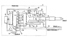
- FIG. 2 is a system configuration diagram showing a configuration of an engine room in the internal combustion engine system of FIG. 1 ;
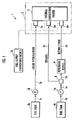
- FIG. 3 is a function explanatory view of an embodiment of functions of a heating medium in the system of FIG. 2 ;
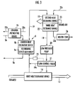
- FIG. 4 is a function explanatory view of another embodiment of functions of a heating medium in the system of FIG. 2 ;
- FIG. 5 is a system configuration diagram showing another configuration example of the internal combustion engine system according to the present invention.
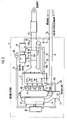
- FIG. 1 is a system configuration diagram showing a configuration example of the internal combustion engine system according to the present invention.
- FIG. 2 is a system configuration diagram showing a configuration of an engine room in the internal combustion engine system of FIG. 1 .
- FIGS. 3 and 4 are function explanatory views of functions of a heating medium in the system of FIG. 2 .
- FIG. 5 is a system configuration diagram showing another configuration example of the internal combustion engine system according to the present invention.
- an internal combustion engine system 1 comprises an internal combustion engine 3 installed in an engine room 2 , a first fuel tank 4 a and a second fuel tank 4 b that provide fuels to the internal combustion engine 3 .
- the internal combustion engine 3 is a hybrid combustion engine switchable between a spark ignition operation and a homogeneous charge compression ignition operation.
- the engine 3 is a flexible fuel vehicle that can be operated with fuels of ethanol and at least one of gasoline and GTL naphtha in an arbitrary mixture ratio.
- the first fuel tank 4 a contains ethanol as a fuel to be provided to the internal combustion engine 3 .
- the second fuel tank 4 b contains gasoline or GTL naphtha as a fuel to be provided to the internal combustion engine 3 .
- the second fuel tank 4 b may contain a mixed fuel of gasoline and GTL naphtha.
- the first fuel tank 4 a is connected to a first injector 6 a of the internal combustion engine 3 via a first duct 5 a.
- a pump 7 a is installed at some midpoint of the first duct 5 a. Ethanol contained in the first fuel tank 4 a is provided to the first injector 6 a by the pump 7 a.
- a distributor 8 is installed at a downstream position of the pump 7 a.
- a second duct 5 b branches from the distributor 8 .
- a reforming device 9 is installed at some midpoint of the second duct 5 b so that the reforming device 9 reforms ethanol provided therein from the distributor 8 via the second duct 5 b by bringing the ethanol being heated into contact with a catalyst, thereby providing diethyl ether.
- the second duct 5 b is connected to a second injector 6 b of the internal combustion engine 3 so that the diethyl ether obtained in the reforming device 9 is provided to the second injector 6 b via the second duct 5 b.
- the second fuel tank 4 b is connected to a third injector 6 c of the internal combustion engine 3 via a third duct 5 c.
- a pump 7 b is installed at some midpoint of the third duct 5 c.
- Liquid hydrocarbon such as gasoline, GTL naphtha or a mixed fuel of gasoline and GTL naphtha is provided to the third injector 6 c by the pump 7 b.
- the first to third injectors 6 a, 6 b and 6 c are electrically connected to a fuel supply controlling device 10 .
- the fuel supply controlling device 10 controls a mixture ratio of ethanol, diethyl ether and the liquid hydrocarbon provided to the internal combustion engine 3 .
- the engine room 2 comprises the internal combustion engine 3 ; an exhaust device 11 for letting out exhaust from the internal combustion engine 3 ; and an intake device 12 for providing intake air to the internal combustion engine 3 .
- the exhaust device 11 comprises an exhaust pipe 13 connected to the internal combustion engine 3 ; and a first heat exchange device 14 located at some midpoint of the exhaust pipe 13 for exchanging heat between exhaust heat provided to the exhaust pipe 13 and a heating medium, thereby heating the heating medium.
- the intake device 12 is connected to the internal combustion engine 3 .
- the intake device 12 comprises a direct line 15 for providing intake air to the internal combustion engine 3 ; and a heating line 16 branching from the direct line 15 at an upstream position of the direct line 15 and merging again with the direct line 15 at a downstream position.
- a first flow control valve 17 a is provided to the direct line 15 at a downstream position of the branch point between the direct line 15 and the heating line 16 .
- a second flow control valve 17 b is provided to the heating line 16 at an upstream position of the merging point of the direct line 15 and the heating line 16 .
- the openings of the flow control valves 17 a and 17 b are adjusted by an electromagnetic control throttle device (not shown).
- a second heat exchange device 18 is provided at some midpoint of the heating line 16 as an intake air heating means for exchanging heat between the heating medium heated by the first heat exchange device 14 and intake air, thereby heating the intake air.
- the heating medium is circulated via a heating medium circulating system 19 installed in the engine room 2 .
- the circulating system 19 comprises from its upstream to its downstream a low pressure pump 20 , a flow control valve 21 , a first heat exchange device 14 , a reforming device 9 and a second heat exchange device 18 .
- the heating medium is heat-exchanged with the intake air in the second heat exchange device 18 , then heat-exchanged with engine cooling water provided by an engine cooling water circulating system 23 in a third heat exchange device 22 provided at a downstream position of the second heat exchange device 18 to cool the heating medium, and then returned to the low pressure pump 20 .
- the heating medium circulating system 19 comprises a bypass 19 a branching from the circulating system 19 at the flow control valve 21 and merging with the circulating system 19 at a position between the first heat exchange device 14 and the reforming device 9 .
- the reforming device 9 also functions as an ethanol heating means by exchanging heat between the heating medium heated by the first heat exchange device 14 and ethanol provided to the reforming device 9 via the second duct 5 b, thereby heating the ethanol.
- the engine cooling water circulating system 23 is composed of a first cooling water pipe 23 a, a second cooling water pipe 23 b, a third cooling water pipe 23 c, and a fourth cooling water pipe 23 d.
- the first cooling water pipe 23 a connects the internal combustion engine 3 to an ethanol preheating device 24 installed in the second duct 5 b at an upstream position of the reforming device 9 , thereby providing engine cooling water heated in the internal combustion engine 3 to the ethanol preheating device 24 .
- the second cooling water pipe 23 b connects the ethanol preheating device 24 to the internal combustion engine 3 , thereby providing engine cooling water cooled in the ethanol preheating device 24 to the internal combustion engine 3 .
- the third cooling water pipe 23 c connects the internal combustion engine 3 to the second heat exchange device 18 via the third heat exchange device 22 , thereby exchanging heat between engine cooling water and the heating medium in the third heat exchange device 22 , and further providing the heated engine cooling water to the second heat exchange device 18 .
- the fourth cooling water pipe 23 d connects the second heat exchange device 18 to the internal combustion engine 3 , thereby providing engine cooling water cooled by heat-exchanging with the intake air in the second heat exchange device 18 to the internal combustion engine 3 .
- the fourth cooling water pipe 23 d is connected to the first cooling water pipe 23 a.
- FIG. 3 there is described an aspect of functions of a heating medium in the internal combustion engine system 1 according to the present embodiment.
- heating medium may include mineral oils, silicone oils and the like having boiling points of 200° C. or higher.
- the heating medium can be well known heating mediums generally used in plants and the like, and no special heating medium is necessary.
- the heating medium is circulated by the low pressure pump 20 , thereby first providing a required amount of the heating medium to the first heat exchange device 14 via the flow control valve 21 while allowing an excess of the heating medium to circumvent the first heat exchange device 14 via the bypass 19 a.
- the first heat exchange device 14 heat is exchanged between exhaust and the provided heating medium to heat the heating medium, and the heating medium heated is provided to the reforming device 9 .
- a temperature sensor 25 is provided at an upstream position of the reforming device 9 .
- the flow control valve 21 is feedback-controlled in response to the temperature of the heating medium detected by the temperature sensor 25 so that the temperature becomes suitable (in general, 200° C.) for reforming ethanol to diethyl ether in the reforming device 9 .
- the flow control valve 21 controls the amount of the heating medium to be provided to the first heat exchange device 14 .
- the reforming device 9 also functions as an ethanol heating means for heating ethanol provided via the second duct 5 b, and configured so that the ethanol and the heating medium form a counter current.
- the heating medium provided to the reforming device 9 first heats the reforming device main body 9 a, and then heats ethanol in the fourth heat exchange device 9 b.
- the reforming device 9 has a heat capacity roughly proportional to its weight. Therefore, when ethanol is directly heated with exhaust, the heat capacity causes temperature variation in the beginning of reforming.
- the reforming can be conducted with stability from the beginning of the reforming by first heating the reforming device 9 with the heating medium up to about a reforming temperature, and then providing ethanol to the reforming device 9 .
- the catalyst when the catalyst is configured to be surrounded by the heating medium, the temperature of the catalyst is stabilized and spatial temperature unevenness is prevented, thereby providing excellent reforming properties.
- an ethanol preheating device 24 is provided on the second duct 5 b at an upstream position of the reforming device 9 , thereby preheating ethanol provided to the reforming device 9 .
- the ethanol preheating device 24 can preheat ethanol to be provided to the reforming device 9 up to about 80° C. by providing engine cooling water heated in the internal combustion engine 3 via the first cooling water pipe 23 a.
- the heating medium drained from the reforming device 9 is subsequently provided to the second heat exchange device 18 , and heat-exchanged with intake air, thereby heating the intake air.
- the heating medium having a considerable quantity of heat even after heating the intake air is subsequently provided to the third heat exchange device 22 , thereby heat-exchanging with engine cooling water provided to the third heat exchange device 22 via the third cooling water pipe 23 c.
- the heating medium is cooled to about 80° C.
- cooled heating medium is returned to the low pressure pump 20 .
- the intake air provided to the second heat exchange device 18 may be preheated by heat-exchanging with engine cooling water provided via the third cooling water pipe 23 c before the intake air is heated by heat exchanging with the heating medium.
- the engine cooling water provided via the third cooling water pipe 23 c is heated in the internal combustion engine 3 and provided to the third heat exchange device 22 as shown in FIG. 2 .
- the engine cooling water provided via the third cooling water pipe 23 c is provided to the third heat exchange device 22 , heated by heat-exchanging with the heating medium, and drained to the fourth cooling water pipe 23 d.
- the heater core 26 can be heated with the engine cooling water, whereby a heater can be used at an early stage.
- warming up can be conducted with the engine cooling water heated in the third heat exchange device 22 .
- the heating medium circulating system 19 is composed of only control systems and heat exchanging systems, and thus pressure loss is small and the system 19 does not require high pressure. Therefore, the low pressure pump 20 can be used for circulating the heating medium.
- the heating medium is required to have a flow rate so that temperature control stability can be maintained for reforming ethanol to diethyl ether in the reforming device 9 .
- the amount of the ethanol is small, and thus the flow rate of the heating medium is not necessarily very high. For example, a flow rate of several liters per minute meets the requirement. Therefore, a small pump is sufficient as the low pressure pump 20 , and thus its electrical power consumption is as small as several tens of watts at the largest.
- the heating medium passing through the low pressure pump 20 has a temperature of about 80° C. by being cooled in the third heat exchange device 22 as described above. Therefore, the low pressure pump 20 requires some heat resistance but does not require a special heat resisting means.
- the heating medium provides high control stability when compared with heating ethanol directly with exhaust because the heating medium has a higher flow rate than the ethanol, has a higher heat capacity and brings about less influence by heat radiation, and the heating medium does not boil during heating.
- the flow control valve 21 is used for distributing the heating medium to the first heat exchange device 14 and the bypass 19 a.
- thermo valve 21 instead of the flow control valve 21 , a thermo valve such as a bimetal type may be used. Use of such a thermo valve simplifies the device configuration because of not requiring power supply or a control circuit.
- ethanol is heated by using a heating medium heated by heat-exchanging with exhaust as mentioned above, thereby easily assuring desired reforming properties in the reforming device 9 .
- a heating medium heated by heat-exchanging with exhaust as mentioned above
- ignition properties of a fuel can be changed continuously, thereby controlling the ignition timing precisely during a homogeneous charge compression ignition operation.
- intake air is heated by using a heating medium heated by heat-exchanging with exhaust as mentioned above, thereby controlling the ignition timing precisely and effectively during a homogeneous charge compression ignition operation.
- the internal combustion engine system 1 of the present embodiment comprises both an ethanol heating means (the reforming device 9 (the fourth heat exchange device 9 b )) and an intake air heating means (the second heat exchange device 18 ) that use a heating medium heated by heat-exchanging with exhaust as mentioned above.
- the internal combustion engine system 1 may comprise only the ethanol heating means or only the intake air heating means. It should be noted that in the case of comprising only the intake air heating means, the internal combustion engine system 1 requires a means for heating ethanol provided to the reforming device 9 with a heat source other than the heating medium.
- FIG. 4 there is described another aspect of functions of a heating medium in the internal combustion engine system 1 according to the present embodiment.
- a heating medium circulating system 19 comprises a control valve 27 at an upstream position of the reforming device 9 ; and an adiabatic storage container 29 connected to a duct 28 a branched at the control valve 27 in which the adiabatic storage container 29 is connected to the heating medium circulating system 19 at a downstream position of the control valve 27 via a duct 28 b.
- the heating medium circulating system 19 further comprises a temperature sensor 30 a for detecting the temperature of a heating medium at an upstream position of the control valve 27 ; and a temperature sensor 30 b in the adiabatic storage container 29 for detecting a temperature of the adiabatic storage container 29 . Both of the temperature sensors 30 a and 30 b are electrically connected to the control valve 27 and output the detected temperatures to the control valve 27 .
- the heating medium circulating system 19 further comprises an absorption air conditioning system regenerator 31 at a downstream position of the reforming device 9 .
- Connected ducts to the absorption air conditioning system regenerator 31 are a water-lithium bromide duct 32 a for providing lithium bromide which has absorbed water from an absorption air conditioning system not shown to the regenerator 31 ; a drainage duct 32 b for draining water obtained by evaporating the lithium bromide which has absorbed water in the absorption air conditioning system regenerator 31 ; and a lithium bromide duct 32 c for providing again lithium bromide regenerated by the evaporation to the absorption air conditioning system.
- FIG. 4 Except the above configuration, the configuration shown in FIG. 4 is the same as that of FIG. 3 . Therefore, the same reference numerals are assigned to the same configuration and explanations thereof are omitted. In FIG. 4 , the ethanol preheating device 24 , the temperature sensor 25 and the heater core 26 are omitted.
- the same heating medium as with FIG. 3 is circulated in the heating medium circulating system 19 with the low pressure pump 20 , and heated with the first heat exchange device 14 as with FIG. 3 .
- the heating medium heated in the first heat exchange device 14 heats ethanol in the reforming device 9 as with FIG. 3 .
- the heating medium heats intake air of the internal combustion engine 3 in the second heat exchange device 18 and then heat-exchanges with engine cooling water in the third heat exchange device 22 , whereby the heating medium is cooled to about 80° C.
- cooled heating medium is returned to the low pressure pump 20 as mentioned above.
- the heating medium is not heated anymore in the first heat exchange device 14 and is cooled. Once the heating medium is cooled, it takes time to heat again the heating medium. Therefore, when the internal combustion engine 3 is operated again, it takes time until the ethanol and the intake air can be heated.
- a control valve 27 detects the halt of the internal combustion engine 3 , and introduces the heating medium to an adiabatic storage container 29 via a duct 28 a, whereby the heating medium is contained in the adiabatic storage container 29 .
- the heating medium is stored at the temperature heated in the first heat exchange device 14 .
- the adiabatic storage container 29 provides the stored heating medium to the heating medium circulating system 19 via the duct 28 b, thereby circulating the heating medium.
- a heating medium with high temperature can be circulated in the heat circulating system from the start of the operation, whereby the ethanol or the intake air can be heated in an extremely short period.
- control valve 27 generally closes the duct 28 a, and thus the heating medium is not introduced to the adiabatic storage container 29 .
- the duct 28 b comprises a check valve not shown so that the heating medium circulating in the heating medium circulating system 19 does not flow from the duct 28 b into the adiabatic storage container 29 .
- the temperature T 1 of the heating medium may become lower than the temperature T 2 in the adiabatic storage container 29 depending on the condition. Therefore, in the configuration shown in FIG. 4 , the temperature T 1 of the heating medium is detected by a temperature sensor 30 a provided in the heating medium circulating system 19 at an upstream position of the control valve 27 , and also the temperature T 2 in the adiabatic storage container 29 is detected by a temperature sensor 30 b provided in the adiabatic storage container 29 . Then the control valve 27 compares the temperatures detected by the temperature sensors 30 a and 30 b. Only when the temperature T 2 in the adiabatic storage container 29 is higher than the temperature T 1 of the heating medium (T 2 >T 1 ), the heating medium is flowed into the adiabatic storage container 29 .
- the heating medium is heated by being introduced to the adiabatic storage container 29 from the control valve 27 via the duct 28 a, subsequently being passed through the adiabatic storage container 29 and being returned to the heating medium circulating system 19 from the duct 28 b. Therefore, the heating medium is heated by the first heat exchange device 14 and also by the adiabatic storage container 29 . As a result, temperature control range during an operation of the internal combustion engine 3 can be increased.
- an absorption air conditioning system regenerator 31 may be provided at some midpoint of the heating medium circulating system 19 , for example, at a position between the reforming device 9 and the second heat exchange device 18 .
- an absorption air conditioning system (not shown) uses water as a coolant and lithium bromide as an absorbing solution. Water absorbed by the lithium bromide is provided to the absorption air conditioning system regenerator 31 via a water-lithium bromide duct 32 a. The absorption air conditioning system regenerator 31 heats and evaporates lithium bromide which has absorbed water by using the heating medium, thereby separating the lithium bromide which has absorbed water into water and lithium bromide. The separated water is drained from a drainage duct 32 b. The lithium bromide separated by the evaporation and regenerated is provided again to the absorption air conditioning system via a lithium bromide duct 32 c.
- FIG. 5 there is shown another internal combustion engine system 41 according to the present embodiment.
- the internal combustion engine system 41 has an identical configuration with the internal combustion engine system 1 shown in FIG. 1 except that the system 41 comprises a fuel tank 42 containing a mixed fuel comprising ethanol and at least one of gasoline and GTL naphtha; and a separator 43 that separates the mixed fuel provided from the fuel tank 42 into an ethanol-water mixture and liquid hydrocarbon such as gasoline, GTL naphtha or a mixed fuel of gasoline and GTL naphtha by adding water to the mixed fuel, and the first duct 5 a and the third duct 5 c are connected to the separator 43 .
- a fuel tank 42 containing a mixed fuel comprising ethanol and at least one of gasoline and GTL naphtha
- a separator 43 that separates the mixed fuel provided from the fuel tank 42 into an ethanol-water mixture and liquid hydrocarbon such as gasoline, GTL naphtha or a mixed fuel of gasoline and GTL naphtha by adding water to the mixed fuel
- the ethanol-water mixture obtained in the separator 43 is provided to the first injector 6 a of the internal combustion engine 3 via the first duct 5 a.
- the reforming device 9 brings the ethanol-water mixture provided from the distributor 8 via the second duct 5 b into contact with a catalyst while heating the ethanol-water mixture, thereby reforming the mixture to a diethyl ether-water mixture.
- the diethyl ether-water mixture obtained in the reforming device 9 is provided to the second injector 6 b via the second duct 5 b.
- the fuel supply controlling device 10 controls a mixture ratio of the ethanol-water mixture, the diethyl ether-water mixture and the liquid hydrocarbon to be provided to the internal combustion engine 3 .
- the functions of a heating medium in the internal combustion engine system 41 are identical with those in the internal combustion engine system 1 except that the ethanol is replaced with the ethanol-water mixture and the diethyl ether is replaced with the diethyl ether-water mixture.
Landscapes
- Engineering & Computer Science (AREA)
- Chemical & Material Sciences (AREA)
- Combustion & Propulsion (AREA)
- Mechanical Engineering (AREA)
- General Engineering & Computer Science (AREA)
- Oil, Petroleum & Natural Gas (AREA)
- Water Supply & Treatment (AREA)
- Biodiversity & Conservation Biology (AREA)
- Biotechnology (AREA)
- Botany (AREA)
- Sustainable Development (AREA)
- Sustainable Energy (AREA)
- Life Sciences & Earth Sciences (AREA)
- Health & Medical Sciences (AREA)
- Public Health (AREA)
- Output Control And Ontrol Of Special Type Engine (AREA)
- Combined Controls Of Internal Combustion Engines (AREA)
- Ignition Installations For Internal Combustion Engines (AREA)
- Electrical Control Of Ignition Timing (AREA)
Abstract
Description
- 1. Field of the Invention
- The present invention relates to an internal combustion engine system switchable between a spark ignition operation and a homogeneous charge compression ignition operation.
- 2. Description of the Related Art
- In recent years, in order to improve fuel efficiency and reduce emission matters in internal combustion engines, compression ignition internal combustion engines represented by homogeneous charge compression ignition internal combustion engines have been under review. In a homogeneous charge compression ignition internal combustion engine, oxygen containing gas and a compression ignition fuel are introduced into a cylinder and compressed to ignite spontaneously.
- However, as distinct from spark ignition internal combustion engines, homogeneous charge compression ignition internal combustion engines have problems that it is difficult to control ignition timing and the engines can be operated safely only in a narrow operating range. More specifically, the problems mean that use of a fuel with high ignitability tends to cause knocking when required load of the engine is high, and that use of a fuel with low ignitability tends to cause misfire when required load of the engine is low. In order to overcome the problems, there is known an internal combustion engine system switchable between a spark ignition operation and a homogeneous charge compression ignition operation depending on operation conditions or the like (for example, see Japanese Patent Laid-Open No. 2001-152919, and No. 2002-130006.)
- Furthermore, in order to overcome the problems, it is conceivable that two or more types of fuels having different ignition characteristics are prepared, and the mixture ratio of the fuels is controlled when the fuels are provided to the homogeneous charge compression ignition internal combustion engine, thereby controlling the ignition timing. Examples of the two or more types of fuels having different ignition characteristics may include a combination of liquid hydrocarbon such as gasoline or GTL naphtha and ethanol.
- Use of ethanol allows the so-called “carbon neutral effect”, thereby contributing to carbon dioxide emission reductions. The carbon neutral effect means that combustion of ethanol derived from plants emits carbon dioxide but the net carbon emissions are zero because the material plants absorb carbon dioxide by carrying out photosynthesis in their growth processes.
- The liquid hydrocarbon and the ethanol may be contained in separate tanks. Alternatively, the liquid hydrocarbon and the ethanol may be contained as a mixed fuel in a single tank and separated into the liquid hydrocarbon and the ethanol as necessary. It is known that addition of water to the mixed fuel of liquid hydrocarbon and ethanol easily separates the fuel into the liquid hydrocarbon and an ethanol-water mixture (for example, see Japanese Patent Laid-Open No. 58-96155).
- When the liquid hydrocarbon is compared to ethanol, ethanol is less self ignitable than the liquid hydrocarbon. Therefore, a mixture ratio of the ethanol and the liquid hydrocarbon is adjusted, thereby changing ignition characteristics, for example, represented by the octane number. As a result, the ignition timing of a homogeneous charge compression ignition can be controlled.
- However, there is demanded development of an internal combustion engine system in which the ignition timing of a homogeneous charge compression ignition can be controlled more effectively.
- In order to overcome the problems, an object of the present invention is to provide an internal combustion engine system switchable between a spark ignition operation and a homogeneous charge compression ignition operation in which the ignition timing of a homogeneous charge compression ignition can be controlled precisely during the homogeneous charge compression ignition operation.
- In order to achieve the object, a first aspect of the internal combustion engine system according to the present invention is an internal combustion engine system switchable between a spark ignition operation and a homogeneous charge compression ignition operation, comprising: a first fuel tank containing ethanol; a second fuel tank containing at least one of gasoline and GTL naphtha; a reforming means for reforming a portion of ethanol provided from the first fuel tank to an internal combustion engine by heating and bringing the ethanol into contact with a catalyst to obtain diethyl ether; a heat exchange means for exchanging heat between exhaust heat of the internal combustion engine and a heating medium to heat the heating medium; an ethanol heating means for heating ethanol provided to the reforming means with the heating medium heated by the heat exchange means; and a fuel supply controlling means for controlling a mixture ratio of ethanol provided from the first fuel tank to the internal combustion engine, at least one of gasoline and GTL naphtha provided from the second fuel tank to the internal combustion engine, and diethyl ether provided from the reforming means to the internal combustion engine.
- According to the first aspect of the internal combustion engine system, a portion of ethanol contained in the first fuel tank can be reformed to diethyl ether with the reforming means. The ethanol has a lower self ignitability than the gasoline and GTL naphtha whereas the diethyl ether has a higher self ignitability than the gasoline and GTL naphtha.
- Therefore, by controlling a mixture ratio of the ethanol, at least one of gasoline and GTL naphtha, and the diethyl ether provided to the internal combustion engine with the fuel supply controlling means, the ignition timing of a homogeneous charge compression ignition can be controlled precisely.
- By the way, when the ethanol is reformed to the diethyl ether by using a catalyst, it is necessary to keep the temperature of ethanol brought into contact with the catalyst to be a constant temperature of about 200° C. For this purpose, it is conceivable that exhaust heat of the internal combustion engine can be used as a heat source for heating the ethanol up to the temperature. However, it is difficult to maintain desired reforming properties by direct use of exhaust heat of the internal combustion engine, because large heat radiation causes ununiform temperatures of the reforming means and ethanol has a large latent heat.
- Therefore, in the first aspect of the internal combustion engine system, heat is exchanged between exhaust heat of the internal combustion engine and a heating medium by using the heat exchange means to heat the heating medium, and the heating medium is used to heat the ethanol with the ethanol heating means. As a result, the temperature of the ethanol can be easily kept at a constant temperature of about 200° C. The ethanol is brought into contact with the catalyst in the reforming means, thereby easily maintaining desired reforming properties.
- Next, a second aspect of the internal combustion engine system according to the present invention is an internal combustion engine system switchable between a spark ignition operation and a homogeneous charge compression ignition operation, comprising: a first fuel tank containing ethanol; a second fuel tank containing at least one of gasoline and GTL naphtha; a reforming means for reforming a portion of ethanol provided from the first fuel tank to an internal combustion engine by heating and bringing the ethanol into contact with a catalyst to obtain diethyl ether; a heat exchange means for exchanging heat between exhaust heat of the internal combustion engine and a heating medium to heat the heating medium; an intake air heating means for heating intake air of the internal combustion engine with the heating medium heated by the heat exchange means; and a fuel supply controlling means for controlling a mixture ratio of ethanol provided from the first fuel tank to the internal combustion engine, at least one of gasoline and GTL naphtha provided from the second fuel tank to the internal combustion engine, and diethyl ether provided from the reforming means to the internal combustion engine.
- According to the second aspect of the internal combustion engine system, as with the first aspect, by controlling a mixture ratio of the ethanol, at least one of gasoline and GTL naphtha, and the diethyl ether provided to the internal combustion engine with the fuel supply controlling means, the ignition timing of a homogeneous charge compression ignition can be controlled precisely.
- In this case, the ignition timing can also be controlled by heating intake air of the internal combustion engine. Therefore, in the second aspect of the internal combustion engine system, heat is exchanged between exhaust heat of the internal combustion engine and a heating medium by using the heat exchange means to heat the heating medium, and the heating medium is used to heat intake air of the internal combustion engine with the intake air heating means.
- As a result, the control of the ignition timing by the function of the fuel supply controlling means can be complemented by the heating of intake air with the intake air heating means, thereby controlling the ignition timing precisely and effectively.
- The second aspect of the internal combustion engine system may further comprise an ethanol heating means for heating ethanol provided to the reforming means with the heating medium heated by the heat exchange means. As a result, the control of the ignition timing by the function of the fuel supply controlling means can be complemented by the heating of intake air in the intake air heating means, and also desired reforming properties can be maintained easily with the reforming means.
- Note that equipping of the ethanol heating means in the second aspect of the internal combustion engine system has the same meaning as equipping of the intake air heating means in the first aspect of the internal combustion engine system.
- In addition, both of the first and second aspects may comprise a fuel tank containing a mixed fuel comprising ethanol and at least one of gasoline and GTL naphtha; and a separating means for separating the mixed fuel provided from the fuel tank into at least one of gasoline and GTL naphtha and an ethanol-water mixture by adding water to the mixed fuel; instead of a first fuel tank containing ethanol and a second fuel tank containing at least one of gasoline and GTL naphtha.
- In this case, as with the first and second aspects, a portion of the ethanol-water mixture obtained in the separating means is reformed to a diethyl ether-water mixture with the reforming means. After that, a mixture ratio of the ethanol-water mixture, at least one of gasoline and GTL naphtha, and the diethyl ether-water mixture to be provided to the internal combustion engine is controlled with the fuel supply controlling means. In the case that the internal combustion engine system comprises the ethanol heating means, heat is exchanged between exhaust heat of the internal combustion engine and a heating medium by using the heat exchange means to heat the heating medium, and the heating medium is used to heat the ethanol-water mixture with the ethanol heating means.
- In each aspect of the internal combustion engine system, the spark ignition operation is carried out during high engine load conditions, while the homogeneous charge compression ignition operation is carried out during low engine load conditions.
- In each aspect of the internal combustion engine system, when the internal combustion engine halts, the heating medium is cooled. As a result, when the internal combustion engine resumes, the heating medium is heated again from the cooled state. Therefore, it takes time until the ethanol, the ethanol-water mixture, or intake air of the internal combustion engine can be heated.
- For this reason, each aspect of the internal combustion engine system preferably comprises an adiabatic storage container for containing the heating medium heated by the heat exchange means and storing the heating medium under adiabatic conditions during a halt of the internal combustion engine. In this each aspect of the internal combustion engine system, the heating medium is housed in the adiabatic storage container on the halt of the internal combustion engine and the heating medium is stored therein during the halt of the internal combustion engine, thereby preventing the heating medium from cooling. As a result, when the internal combustion engine resumes, the ethanol, the ethanol-water mixture, or intake air of the internal combustion engine can be heated at once.
- Examples of the adiabatic storage container may include a heat storage container for storing cooling water heated by a water cooled internal combustion engine for the purpose of rapid warming up (see Japanese Patent Laid-Open No. 2001-207845).
- When each aspect of the internal combustion engine system comprises the adiabatic storage container, the system preferably further comprises a first thermal detecting means for detecting a temperature of the adiabatic storage container; a second thermal detecting means for detecting a temperature of the heating medium heated by the heat exchange means; and a flow controlling means for flowing the heating medium to the adiabatic storage container only when the temperature detected by the first thermal detecting means is higher than the temperature detected by the second thermal detecting means during an operation of the internal combustion engine.
- The flow controlling means flows the heating medium to the adiabatic storage container only when the temperature detected by the first thermal detecting means is higher than the temperature detected by the second thermal detecting means during an operation of the internal combustion engine. As a result, the heating medium is heated by the heat exchange means and also by the adiabatic storage container, thereby extending the range of temperature control during an operation of the internal combustion engine.
-
FIG. 1 is a system configuration diagram showing a configuration example of the internal combustion engine system according to the present invention; -
FIG. 2 is a system configuration diagram showing a configuration of an engine room in the internal combustion engine system ofFIG. 1 ; -
FIG. 3 is a function explanatory view of an embodiment of functions of a heating medium in the system ofFIG. 2 ; -
FIG. 4 is a function explanatory view of another embodiment of functions of a heating medium in the system ofFIG. 2 ; and -
FIG. 5 is a system configuration diagram showing another configuration example of the internal combustion engine system according to the present invention. - Hereinafter, embodiments of the present invention will be described in further detail with reference to the attached drawings.
FIG. 1 is a system configuration diagram showing a configuration example of the internal combustion engine system according to the present invention.FIG. 2 is a system configuration diagram showing a configuration of an engine room in the internal combustion engine system ofFIG. 1 .FIGS. 3 and 4 are function explanatory views of functions of a heating medium in the system ofFIG. 2 .FIG. 5 is a system configuration diagram showing another configuration example of the internal combustion engine system according to the present invention. - As shown in
FIG. 1 , an internal combustion engine system 1 according to the present embodiment comprises aninternal combustion engine 3 installed in anengine room 2, afirst fuel tank 4 a and asecond fuel tank 4 b that provide fuels to theinternal combustion engine 3. Theinternal combustion engine 3 is a hybrid combustion engine switchable between a spark ignition operation and a homogeneous charge compression ignition operation. Theengine 3 is a flexible fuel vehicle that can be operated with fuels of ethanol and at least one of gasoline and GTL naphtha in an arbitrary mixture ratio. Thefirst fuel tank 4 a contains ethanol as a fuel to be provided to theinternal combustion engine 3. Thesecond fuel tank 4 b contains gasoline or GTL naphtha as a fuel to be provided to theinternal combustion engine 3. Thesecond fuel tank 4 b may contain a mixed fuel of gasoline and GTL naphtha. - The
first fuel tank 4 a is connected to afirst injector 6 a of theinternal combustion engine 3 via afirst duct 5 a. Apump 7 a is installed at some midpoint of thefirst duct 5 a. Ethanol contained in thefirst fuel tank 4 a is provided to thefirst injector 6 a by thepump 7 a. - In this case, a
distributor 8 is installed at a downstream position of thepump 7 a. Asecond duct 5 b branches from thedistributor 8. A reformingdevice 9 is installed at some midpoint of thesecond duct 5 b so that the reformingdevice 9 reforms ethanol provided therein from thedistributor 8 via thesecond duct 5 b by bringing the ethanol being heated into contact with a catalyst, thereby providing diethyl ether. Thesecond duct 5 b is connected to asecond injector 6 b of theinternal combustion engine 3 so that the diethyl ether obtained in the reformingdevice 9 is provided to thesecond injector 6 b via thesecond duct 5 b. - On the other hand, the
second fuel tank 4 b is connected to athird injector 6 c of theinternal combustion engine 3 via athird duct 5 c. Apump 7 b is installed at some midpoint of thethird duct 5 c. Liquid hydrocarbon such as gasoline, GTL naphtha or a mixed fuel of gasoline and GTL naphtha is provided to thethird injector 6 c by thepump 7 b. - In the internal combustion engine system 1, the first to
third injectors supply controlling device 10. The fuelsupply controlling device 10 controls a mixture ratio of ethanol, diethyl ether and the liquid hydrocarbon provided to theinternal combustion engine 3. - As shown in
FIG. 2 , theengine room 2 comprises theinternal combustion engine 3; anexhaust device 11 for letting out exhaust from theinternal combustion engine 3; and anintake device 12 for providing intake air to theinternal combustion engine 3. - The
exhaust device 11 comprises anexhaust pipe 13 connected to theinternal combustion engine 3; and a firstheat exchange device 14 located at some midpoint of theexhaust pipe 13 for exchanging heat between exhaust heat provided to theexhaust pipe 13 and a heating medium, thereby heating the heating medium. - On the other hand, the
intake device 12 is connected to theinternal combustion engine 3. Theintake device 12 comprises adirect line 15 for providing intake air to theinternal combustion engine 3; and aheating line 16 branching from thedirect line 15 at an upstream position of thedirect line 15 and merging again with thedirect line 15 at a downstream position. A firstflow control valve 17 a is provided to thedirect line 15 at a downstream position of the branch point between thedirect line 15 and theheating line 16. A secondflow control valve 17 b is provided to theheating line 16 at an upstream position of the merging point of thedirect line 15 and theheating line 16. The openings of theflow control valves heat exchange device 18 is provided at some midpoint of theheating line 16 as an intake air heating means for exchanging heat between the heating medium heated by the firstheat exchange device 14 and intake air, thereby heating the intake air. - The heating medium is circulated via a heating
medium circulating system 19 installed in theengine room 2. The circulatingsystem 19 comprises from its upstream to its downstream alow pressure pump 20, aflow control valve 21, a firstheat exchange device 14, a reformingdevice 9 and a secondheat exchange device 18. The heating medium is heat-exchanged with the intake air in the secondheat exchange device 18, then heat-exchanged with engine cooling water provided by an engine coolingwater circulating system 23 in a thirdheat exchange device 22 provided at a downstream position of the secondheat exchange device 18 to cool the heating medium, and then returned to thelow pressure pump 20. The heatingmedium circulating system 19 comprises abypass 19 a branching from the circulatingsystem 19 at theflow control valve 21 and merging with the circulatingsystem 19 at a position between the firstheat exchange device 14 and the reformingdevice 9. The reformingdevice 9 also functions as an ethanol heating means by exchanging heat between the heating medium heated by the firstheat exchange device 14 and ethanol provided to the reformingdevice 9 via thesecond duct 5 b, thereby heating the ethanol. - The engine cooling
water circulating system 23 is composed of a firstcooling water pipe 23 a, a secondcooling water pipe 23 b, a thirdcooling water pipe 23 c, and a fourthcooling water pipe 23 d. The firstcooling water pipe 23 a connects theinternal combustion engine 3 to anethanol preheating device 24 installed in thesecond duct 5 b at an upstream position of the reformingdevice 9, thereby providing engine cooling water heated in theinternal combustion engine 3 to theethanol preheating device 24. The secondcooling water pipe 23 b connects theethanol preheating device 24 to theinternal combustion engine 3, thereby providing engine cooling water cooled in theethanol preheating device 24 to theinternal combustion engine 3. The thirdcooling water pipe 23 c connects theinternal combustion engine 3 to the secondheat exchange device 18 via the thirdheat exchange device 22, thereby exchanging heat between engine cooling water and the heating medium in the thirdheat exchange device 22, and further providing the heated engine cooling water to the secondheat exchange device 18. The fourthcooling water pipe 23 d connects the secondheat exchange device 18 to theinternal combustion engine 3, thereby providing engine cooling water cooled by heat-exchanging with the intake air in the secondheat exchange device 18 to theinternal combustion engine 3. The fourthcooling water pipe 23 d is connected to the firstcooling water pipe 23 a. - Referring now to
FIG. 3 , there is described an aspect of functions of a heating medium in the internal combustion engine system 1 according to the present embodiment. - Examples of the heating medium may include mineral oils, silicone oils and the like having boiling points of 200° C. or higher. The heating medium can be well known heating mediums generally used in plants and the like, and no special heating medium is necessary.
- In the heating
medium circulating system 19, the heating medium is circulated by thelow pressure pump 20, thereby first providing a required amount of the heating medium to the firstheat exchange device 14 via theflow control valve 21 while allowing an excess of the heating medium to circumvent the firstheat exchange device 14 via thebypass 19 a. In the firstheat exchange device 14, heat is exchanged between exhaust and the provided heating medium to heat the heating medium, and the heating medium heated is provided to the reformingdevice 9. - At an upstream position of the reforming
device 9, atemperature sensor 25 is provided. Theflow control valve 21 is feedback-controlled in response to the temperature of the heating medium detected by thetemperature sensor 25 so that the temperature becomes suitable (in general, 200° C.) for reforming ethanol to diethyl ether in the reformingdevice 9. Thus theflow control valve 21 controls the amount of the heating medium to be provided to the firstheat exchange device 14. - The reforming
device 9 also functions as an ethanol heating means for heating ethanol provided via thesecond duct 5 b, and configured so that the ethanol and the heating medium form a counter current. The heating medium provided to the reformingdevice 9 first heats the reforming devicemain body 9 a, and then heats ethanol in the fourthheat exchange device 9 b. - The reforming
device 9 has a heat capacity roughly proportional to its weight. Therefore, when ethanol is directly heated with exhaust, the heat capacity causes temperature variation in the beginning of reforming. However, in the present embodiment, the reforming can be conducted with stability from the beginning of the reforming by first heating the reformingdevice 9 with the heating medium up to about a reforming temperature, and then providing ethanol to the reformingdevice 9. In this case, when the catalyst is configured to be surrounded by the heating medium, the temperature of the catalyst is stabilized and spatial temperature unevenness is prevented, thereby providing excellent reforming properties. - In the present embodiment, an
ethanol preheating device 24 is provided on thesecond duct 5 b at an upstream position of the reformingdevice 9, thereby preheating ethanol provided to the reformingdevice 9. As a result, the required heat capacity of the heating medium can be prevented from becoming excessive. Theethanol preheating device 24 can preheat ethanol to be provided to the reformingdevice 9 up to about 80° C. by providing engine cooling water heated in theinternal combustion engine 3 via the firstcooling water pipe 23 a. - The heating medium drained from the reforming
device 9 is subsequently provided to the secondheat exchange device 18, and heat-exchanged with intake air, thereby heating the intake air. The heating medium having a considerable quantity of heat even after heating the intake air is subsequently provided to the thirdheat exchange device 22, thereby heat-exchanging with engine cooling water provided to the thirdheat exchange device 22 via the thirdcooling water pipe 23 c. As a result, the heating medium is cooled to about 80° C. Thus cooled heating medium is returned to thelow pressure pump 20. - The intake air provided to the second
heat exchange device 18 may be preheated by heat-exchanging with engine cooling water provided via the thirdcooling water pipe 23 c before the intake air is heated by heat exchanging with the heating medium. In this case, the engine cooling water provided via the thirdcooling water pipe 23 c is heated in theinternal combustion engine 3 and provided to the thirdheat exchange device 22 as shown inFIG. 2 . - The engine cooling water provided via the third
cooling water pipe 23 c is provided to the thirdheat exchange device 22, heated by heat-exchanging with the heating medium, and drained to the fourthcooling water pipe 23 d. In this case, by providing aheater core 26 at some midpoint of the fourthcooling water pipe 23 d, theheater core 26 can be heated with the engine cooling water, whereby a heater can be used at an early stage. Alternatively, warming up can be conducted with the engine cooling water heated in the thirdheat exchange device 22. - The heating
medium circulating system 19 is composed of only control systems and heat exchanging systems, and thus pressure loss is small and thesystem 19 does not require high pressure. Therefore, thelow pressure pump 20 can be used for circulating the heating medium. - The heating medium is required to have a flow rate so that temperature control stability can be maintained for reforming ethanol to diethyl ether in the reforming
device 9. However, the amount of the ethanol is small, and thus the flow rate of the heating medium is not necessarily very high. For example, a flow rate of several liters per minute meets the requirement. Therefore, a small pump is sufficient as thelow pressure pump 20, and thus its electrical power consumption is as small as several tens of watts at the largest. - The heating medium passing through the
low pressure pump 20 has a temperature of about 80° C. by being cooled in the thirdheat exchange device 22 as described above. Therefore, thelow pressure pump 20 requires some heat resistance but does not require a special heat resisting means. - Use of the heating medium provides high control stability when compared with heating ethanol directly with exhaust because the heating medium has a higher flow rate than the ethanol, has a higher heat capacity and brings about less influence by heat radiation, and the heating medium does not boil during heating.
- In the present embodiment, the
flow control valve 21 is used for distributing the heating medium to the firstheat exchange device 14 and thebypass 19 a. - Alternatively, instead of the
flow control valve 21, a thermo valve such as a bimetal type may be used. Use of such a thermo valve simplifies the device configuration because of not requiring power supply or a control circuit. - According to the internal combustion engine system 1 of the present embodiment, ethanol is heated by using a heating medium heated by heat-exchanging with exhaust as mentioned above, thereby easily assuring desired reforming properties in the reforming
device 9. As a result, by controlling a mixture ratio of ethanol, diethyl ether and the liquid hydrocarbon, ignition properties of a fuel can be changed continuously, thereby controlling the ignition timing precisely during a homogeneous charge compression ignition operation. - In addition, according to the internal combustion engine system 1 of the present embodiment, intake air is heated by using a heating medium heated by heat-exchanging with exhaust as mentioned above, thereby controlling the ignition timing precisely and effectively during a homogeneous charge compression ignition operation.
- The internal combustion engine system 1 of the present embodiment comprises both an ethanol heating means (the reforming device 9 (the fourth
heat exchange device 9 b)) and an intake air heating means (the second heat exchange device 18) that use a heating medium heated by heat-exchanging with exhaust as mentioned above. However, the internal combustion engine system 1 may comprise only the ethanol heating means or only the intake air heating means. It should be noted that in the case of comprising only the intake air heating means, the internal combustion engine system 1 requires a means for heating ethanol provided to the reformingdevice 9 with a heat source other than the heating medium. - Referring now to
FIG. 4 , there is described another aspect of functions of a heating medium in the internal combustion engine system 1 according to the present embodiment. - As for the configuration shown in
FIG. 4 , a heatingmedium circulating system 19 comprises acontrol valve 27 at an upstream position of the reformingdevice 9; and anadiabatic storage container 29 connected to aduct 28 a branched at thecontrol valve 27 in which theadiabatic storage container 29 is connected to the heatingmedium circulating system 19 at a downstream position of thecontrol valve 27 via aduct 28 b. The heatingmedium circulating system 19 further comprises atemperature sensor 30 a for detecting the temperature of a heating medium at an upstream position of thecontrol valve 27; and atemperature sensor 30 b in theadiabatic storage container 29 for detecting a temperature of theadiabatic storage container 29. Both of thetemperature sensors control valve 27 and output the detected temperatures to thecontrol valve 27. - The heating
medium circulating system 19 further comprises an absorption air conditioning system regenerator 31 at a downstream position of the reformingdevice 9. Connected ducts to the absorption airconditioning system regenerator 31 are a water-lithium bromide duct 32 a for providing lithium bromide which has absorbed water from an absorption air conditioning system not shown to theregenerator 31; adrainage duct 32 b for draining water obtained by evaporating the lithium bromide which has absorbed water in the absorption airconditioning system regenerator 31; and alithium bromide duct 32 c for providing again lithium bromide regenerated by the evaporation to the absorption air conditioning system. - Except the above configuration, the configuration shown in
FIG. 4 is the same as that ofFIG. 3 . Therefore, the same reference numerals are assigned to the same configuration and explanations thereof are omitted. InFIG. 4 , theethanol preheating device 24, thetemperature sensor 25 and theheater core 26 are omitted. - In the configuration shown in
FIG. 4 , the same heating medium as withFIG. 3 is circulated in the heatingmedium circulating system 19 with thelow pressure pump 20, and heated with the firstheat exchange device 14 as withFIG. 3 . The heating medium heated in the firstheat exchange device 14 heats ethanol in the reformingdevice 9 as withFIG. 3 . Subsequently, the heating medium heats intake air of theinternal combustion engine 3 in the secondheat exchange device 18 and then heat-exchanges with engine cooling water in the thirdheat exchange device 22, whereby the heating medium is cooled to about 80° C. Thus cooled heating medium is returned to thelow pressure pump 20 as mentioned above. - By the way, when the
internal combustion engine 3 is halted, the heating medium is not heated anymore in the firstheat exchange device 14 and is cooled. Once the heating medium is cooled, it takes time to heat again the heating medium. Therefore, when theinternal combustion engine 3 is operated again, it takes time until the ethanol and the intake air can be heated. - Then in configuration shown in
FIG. 4 , when theinternal combustion engine 3 is halted, acontrol valve 27 detects the halt of theinternal combustion engine 3, and introduces the heating medium to anadiabatic storage container 29 via aduct 28 a, whereby the heating medium is contained in theadiabatic storage container 29. Thus the heating medium is stored at the temperature heated in the firstheat exchange device 14. On the other hand, on detecting the operation of theinternal combustion engine 3, theadiabatic storage container 29 provides the stored heating medium to the heatingmedium circulating system 19 via theduct 28 b, thereby circulating the heating medium. As a result, a heating medium with high temperature can be circulated in the heat circulating system from the start of the operation, whereby the ethanol or the intake air can be heated in an extremely short period. - In this case, the
control valve 27 generally closes theduct 28 a, and thus the heating medium is not introduced to theadiabatic storage container 29. Theduct 28 b comprises a check valve not shown so that the heating medium circulating in the heatingmedium circulating system 19 does not flow from theduct 28 b into theadiabatic storage container 29. - By the way, during an operation of the
internal combustion engine 3 and the heating medium circulating in the heatingmedium circulating system 19, the temperature T1 of the heating medium may become lower than the temperature T2 in theadiabatic storage container 29 depending on the condition. Therefore, in the configuration shown inFIG. 4 , the temperature T1 of the heating medium is detected by atemperature sensor 30 a provided in the heatingmedium circulating system 19 at an upstream position of thecontrol valve 27, and also the temperature T2 in theadiabatic storage container 29 is detected by atemperature sensor 30 b provided in theadiabatic storage container 29. Then thecontrol valve 27 compares the temperatures detected by thetemperature sensors adiabatic storage container 29 is higher than the temperature T1 of the heating medium (T2>T1), the heating medium is flowed into theadiabatic storage container 29. - In this case, the heating medium is heated by being introduced to the
adiabatic storage container 29 from thecontrol valve 27 via theduct 28 a, subsequently being passed through theadiabatic storage container 29 and being returned to the heatingmedium circulating system 19 from theduct 28 b. Therefore, the heating medium is heated by the firstheat exchange device 14 and also by theadiabatic storage container 29. As a result, temperature control range during an operation of theinternal combustion engine 3 can be increased. - In the configuration of
FIG. 4 , an absorption airconditioning system regenerator 31 may be provided at some midpoint of the heatingmedium circulating system 19, for example, at a position between the reformingdevice 9 and the secondheat exchange device 18. For example, an absorption air conditioning system (not shown) uses water as a coolant and lithium bromide as an absorbing solution. Water absorbed by the lithium bromide is provided to the absorption air conditioning system regenerator 31 via a water-lithium bromide duct 32 a. The absorption air conditioning system regenerator 31 heats and evaporates lithium bromide which has absorbed water by using the heating medium, thereby separating the lithium bromide which has absorbed water into water and lithium bromide. The separated water is drained from adrainage duct 32 b. The lithium bromide separated by the evaporation and regenerated is provided again to the absorption air conditioning system via alithium bromide duct 32 c. - In
FIG. 5 , there is shown another internalcombustion engine system 41 according to the present embodiment. The internalcombustion engine system 41 has an identical configuration with the internal combustion engine system 1 shown inFIG. 1 except that thesystem 41 comprises afuel tank 42 containing a mixed fuel comprising ethanol and at least one of gasoline and GTL naphtha; and aseparator 43 that separates the mixed fuel provided from thefuel tank 42 into an ethanol-water mixture and liquid hydrocarbon such as gasoline, GTL naphtha or a mixed fuel of gasoline and GTL naphtha by adding water to the mixed fuel, and thefirst duct 5 a and thethird duct 5 c are connected to theseparator 43. - In the internal
combustion engine system 41, the ethanol-water mixture obtained in theseparator 43 is provided to thefirst injector 6 a of theinternal combustion engine 3 via thefirst duct 5 a. The reformingdevice 9 brings the ethanol-water mixture provided from thedistributor 8 via thesecond duct 5 b into contact with a catalyst while heating the ethanol-water mixture, thereby reforming the mixture to a diethyl ether-water mixture. The diethyl ether-water mixture obtained in the reformingdevice 9 is provided to thesecond injector 6 b via thesecond duct 5 b. - Subsequently, the fuel
supply controlling device 10 controls a mixture ratio of the ethanol-water mixture, the diethyl ether-water mixture and the liquid hydrocarbon to be provided to theinternal combustion engine 3. - The functions of a heating medium in the internal
combustion engine system 41 are identical with those in the internal combustion engine system 1 except that the ethanol is replaced with the ethanol-water mixture and the diethyl ether is replaced with the diethyl ether-water mixture.
Claims (18)
Applications Claiming Priority (2)
| Application Number | Priority Date | Filing Date | Title |
|---|---|---|---|
| JP2006294065A JP2008019848A (en) | 2006-06-15 | 2006-10-30 | Internal combustion engine system |
| JP2006-294065 | 2006-10-30 |
Publications (2)
| Publication Number | Publication Date |
|---|---|
| US20080098985A1 true US20080098985A1 (en) | 2008-05-01 |
| US7661414B2 US7661414B2 (en) | 2010-02-16 |
Family
ID=39328634
Family Applications (1)
| Application Number | Title | Priority Date | Filing Date |
|---|---|---|---|
| US11/976,833 Expired - Fee Related US7661414B2 (en) | 2006-10-30 | 2007-10-29 | Internal combustion engine system |
Country Status (2)
| Country | Link |
|---|---|
| US (1) | US7661414B2 (en) |
| BR (1) | BRPI0703981A2 (en) |
Cited By (26)
| Publication number | Priority date | Publication date | Assignee | Title |
|---|---|---|---|---|
| US20090287391A1 (en) * | 2008-05-16 | 2009-11-19 | Woodward Governor Company | Engine Fuel Control System |
| US20110137537A1 (en) * | 2010-04-08 | 2011-06-09 | Ford Global Technologies, Llc | Operating an engine with reformate |
| US20110132323A1 (en) * | 2010-04-08 | 2011-06-09 | Ford Global Technologies, Llc | Method for improving transient engine operation |
| US20110132286A1 (en) * | 2010-04-08 | 2011-06-09 | Ford Global Technologies, Llc | Method for Operating a Charge Diluted Engine |
| US20110132285A1 (en) * | 2010-04-08 | 2011-06-09 | Ford Global Technologies, Llc | Method for operating an engine |
| US20110132289A1 (en) * | 2010-04-08 | 2011-06-09 | Ford Global Technologies, Llc | Selectively Storing Reformate |
| US20110132283A1 (en) * | 2010-04-08 | 2011-06-09 | Ford Global Technologies, Llc | Ignition Control for Reformate Engine |
| US20110132321A1 (en) * | 2010-04-08 | 2011-06-09 | Ford Global Technologies, Llc | Fuel Injector Diagnostic for Dual Fuel Engine |
| US20110132287A1 (en) * | 2010-04-08 | 2011-06-09 | Ford Global Technologies, Llc | Pump Control for Reformate Fuel Storage Tank |
| US20110132306A1 (en) * | 2010-04-08 | 2011-06-09 | Ford Global Technologies, Llc | Method for Operating an Engine with a Fuel Reformer |
| US20110132290A1 (en) * | 2010-04-08 | 2011-06-09 | Ford Global Technologies, Llc | Method for operating a vehicle with a fuel reformer |
| US20110132288A1 (en) * | 2010-04-08 | 2011-06-09 | Ford Global Technologies, Llc | Engine Fuel Reformer Monitoring |
| US20110132326A1 (en) * | 2010-04-08 | 2011-06-09 | Ford Global Technologies, Llc | Reformate Control via Accelerometer |
| US20110132284A1 (en) * | 2010-04-08 | 2011-06-09 | Ford Global Technologies, Llc | Method for Operating an Engine with Variable Charge Density |
| WO2011120618A1 (en) * | 2010-03-31 | 2011-10-06 | Haldor Topsøe A/S | Method and system for operating a compression ignition engine on alcohol containing primary fuels |
| WO2011120615A1 (en) * | 2010-03-31 | 2011-10-06 | Haldor Topsøe A/S | Method and system for operating a pressure ignition engine |
| US20170045003A1 (en) * | 2014-04-23 | 2017-02-16 | American United Energy, Inc. | Fuel control systems for operating gasoline engines based on ethanol-water-hydrogen mixture fuels |
| US10378427B2 (en) | 2017-03-31 | 2019-08-13 | Saudi Arabian Oil Company | Nitrogen enriched air supply for gasoline compression ignition combustion |
| US10378462B1 (en) | 2018-01-31 | 2019-08-13 | Saudi Arabian Oil Company | Heat exchanger configuration for adsorption-based onboard octane on-demand and cetane on-demand |
| US10408139B1 (en) | 2018-03-29 | 2019-09-10 | Saudi Arabian Oil Company | Solvent-based adsorbent regeneration for onboard octane on-demand and cetane on-demand |
| US10422288B1 (en) | 2018-03-29 | 2019-09-24 | Saudi Arabian Oil Company | Adsorbent circulation for onboard octane on-demand and cetane on-demand |
| US10436126B2 (en) | 2018-01-31 | 2019-10-08 | Saudi Arabian Oil Company | Adsorption-based fuel systems for onboard cetane on-demand and octane on-demand |
| US10508017B2 (en) | 2017-10-13 | 2019-12-17 | Saudi Arabian Oil Company | Point-of-sale octane/cetane-on-demand systems for automotive engines |
| WO2022067409A1 (en) * | 2020-10-01 | 2022-04-07 | Robert Bosch Limitada | Method for managing the temperature of fuel injected into an internal-combustion engine |
| US12078115B1 (en) * | 2023-06-20 | 2024-09-03 | Caterpillar Inc. | Systems and methods for pilot fuel synthesis using engine waste heat |
| US20260015980A1 (en) * | 2024-07-09 | 2026-01-15 | Caterpillar Inc. | Systems and methods for controlling cylinder combustion in a dual fuel engine using in-cylinder pressure sensing |
Families Citing this family (8)
| Publication number | Priority date | Publication date | Assignee | Title |
|---|---|---|---|---|
| JP4789116B2 (en) * | 2007-05-17 | 2011-10-12 | 本田技研工業株式会社 | Ethanol fuel reforming system for internal combustion engine |
| US8099949B2 (en) | 2008-05-15 | 2012-01-24 | Ford Global Technologies, Llc | Engine exhaust temperature regulation |
| US8397701B2 (en) * | 2008-07-31 | 2013-03-19 | Ford Global Technologies, Llc | Fuel system for multi-fuel engine |
| DE102012014755A1 (en) * | 2012-07-26 | 2014-05-15 | Man Truck & Bus Ag | Method and apparatus for converting an alcohol into a fuel mixture |
| US9827850B2 (en) * | 2016-03-30 | 2017-11-28 | Saudi Arabian Oil Company | Adjusting a fuel on-board a vehicle |
| CN112020601B (en) * | 2018-04-25 | 2023-03-21 | 沃尔沃卡车集团 | Internal combustion engine arrangement and method of controlling operation thereof |
| US11549451B1 (en) | 2022-04-26 | 2023-01-10 | Caterpillar Inc. | Intake bypass for liquid fuel engine |
| US12006886B1 (en) * | 2023-03-07 | 2024-06-11 | Caterpillar Inc. | Systems and methods for pilot fuel synthesis |
Citations (12)
| Publication number | Priority date | Publication date | Assignee | Title |
|---|---|---|---|---|
| US4210103A (en) * | 1977-04-04 | 1980-07-01 | Southwest Research Institute | Fuel system for and a method of operating a spark-ignited internal combustion engine |
| US4385593A (en) * | 1981-04-13 | 1983-05-31 | The Chemithon Corporation | Introduction of alcohol-water mixture into gasoline-operated engine |
| US20040250790A1 (en) * | 2003-06-12 | 2004-12-16 | Heywood John B. | High compression ratio, high power density homogeneous charge compression ignition engines using hydrogen and carbon monoxide to enhance auto-ignition resistance |
| US20070163537A1 (en) * | 2006-01-13 | 2007-07-19 | Honda Motor Co., Ltd. | Homogeneous charge compression ignition internal combustion engine |
| US20070204813A1 (en) * | 2006-03-01 | 2007-09-06 | Nissan Motor Co., Ltd. | Reforming apparatus, internal combustion engine with reforming apparatus, and fuel cell system with reforming apparatus |
| US20070221163A1 (en) * | 2006-03-23 | 2007-09-27 | Honda Motor Co., Ltd. | Internal combustion engine system |
| US7290505B2 (en) * | 2005-08-04 | 2007-11-06 | Honda Motor Co., Ltd. | Internal combustion engine system |
| US20080010993A1 (en) * | 2006-06-13 | 2008-01-17 | Monsanto Technology Llc | Reformed alcohol power systems |
| US7406947B2 (en) * | 2005-11-30 | 2008-08-05 | Ford Global Technologies, Llc | System and method for tip-in knock compensation |
| US7412966B2 (en) * | 2005-11-30 | 2008-08-19 | Ford Global Technologies, Llc | Engine output control system and method |
| US20080282998A1 (en) * | 2007-05-17 | 2008-11-20 | Honda Motor Co., Ltd. | Ethanol fuel reforming system for internal combustion engines |
| US7461628B2 (en) * | 2006-12-01 | 2008-12-09 | Ford Global Technologies, Llc | Multiple combustion mode engine using direct alcohol injection |
Family Cites Families (5)
| Publication number | Priority date | Publication date | Assignee | Title |
|---|---|---|---|---|
| JPS5896155A (en) | 1981-12-02 | 1983-06-08 | Mazda Motor Corp | Fuel feeding apparatus for engine |
| JP4253426B2 (en) | 1999-09-14 | 2009-04-15 | 日産自動車株式会社 | Compression self-ignition gasoline engine |
| JP4062870B2 (en) | 2000-10-19 | 2008-03-19 | 日産自動車株式会社 | Combustion control device for internal combustion engine |
| JP2008019848A (en) * | 2006-06-15 | 2008-01-31 | Honda Motor Co Ltd | Internal combustion engine system |
| JP4449956B2 (en) * | 2006-08-04 | 2010-04-14 | トヨタ自動車株式会社 | Internal combustion engine |
-
2007
- 2007-10-29 BR BRPI0703981-6A patent/BRPI0703981A2/en not_active Application Discontinuation
- 2007-10-29 US US11/976,833 patent/US7661414B2/en not_active Expired - Fee Related
Patent Citations (12)
| Publication number | Priority date | Publication date | Assignee | Title |
|---|---|---|---|---|
| US4210103A (en) * | 1977-04-04 | 1980-07-01 | Southwest Research Institute | Fuel system for and a method of operating a spark-ignited internal combustion engine |
| US4385593A (en) * | 1981-04-13 | 1983-05-31 | The Chemithon Corporation | Introduction of alcohol-water mixture into gasoline-operated engine |
| US20040250790A1 (en) * | 2003-06-12 | 2004-12-16 | Heywood John B. | High compression ratio, high power density homogeneous charge compression ignition engines using hydrogen and carbon monoxide to enhance auto-ignition resistance |
| US7290505B2 (en) * | 2005-08-04 | 2007-11-06 | Honda Motor Co., Ltd. | Internal combustion engine system |
| US7406947B2 (en) * | 2005-11-30 | 2008-08-05 | Ford Global Technologies, Llc | System and method for tip-in knock compensation |
| US7412966B2 (en) * | 2005-11-30 | 2008-08-19 | Ford Global Technologies, Llc | Engine output control system and method |
| US20070163537A1 (en) * | 2006-01-13 | 2007-07-19 | Honda Motor Co., Ltd. | Homogeneous charge compression ignition internal combustion engine |
| US20070204813A1 (en) * | 2006-03-01 | 2007-09-06 | Nissan Motor Co., Ltd. | Reforming apparatus, internal combustion engine with reforming apparatus, and fuel cell system with reforming apparatus |
| US20070221163A1 (en) * | 2006-03-23 | 2007-09-27 | Honda Motor Co., Ltd. | Internal combustion engine system |
| US20080010993A1 (en) * | 2006-06-13 | 2008-01-17 | Monsanto Technology Llc | Reformed alcohol power systems |
| US7461628B2 (en) * | 2006-12-01 | 2008-12-09 | Ford Global Technologies, Llc | Multiple combustion mode engine using direct alcohol injection |
| US20080282998A1 (en) * | 2007-05-17 | 2008-11-20 | Honda Motor Co., Ltd. | Ethanol fuel reforming system for internal combustion engines |
Cited By (60)
| Publication number | Priority date | Publication date | Assignee | Title |
|---|---|---|---|---|
| US20090287391A1 (en) * | 2008-05-16 | 2009-11-19 | Woodward Governor Company | Engine Fuel Control System |
| US7823562B2 (en) * | 2008-05-16 | 2010-11-02 | Woodward Governor Company | Engine fuel control system |
| CN102066725B (en) * | 2008-05-16 | 2013-10-30 | 伍德沃德公司 | Engine Fuel Control System |
| WO2011120618A1 (en) * | 2010-03-31 | 2011-10-06 | Haldor Topsøe A/S | Method and system for operating a compression ignition engine on alcohol containing primary fuels |
| WO2011120615A1 (en) * | 2010-03-31 | 2011-10-06 | Haldor Topsøe A/S | Method and system for operating a pressure ignition engine |
| CN102859144A (en) * | 2010-03-31 | 2013-01-02 | 赫多特普索化工设备公司 | Method and system for operating a compression ignition engine on alcohol containing primary fuels |
| CN102947571A (en) * | 2010-03-31 | 2013-02-27 | 赫多特普索化工设备公司 | Method and system for operating pressure ignition engine |
| US9109506B2 (en) | 2010-03-31 | 2015-08-18 | Haldor Topsoe A/S | Method for operating a pressure ignition engine |
| US8820269B2 (en) | 2010-03-31 | 2014-09-02 | Haldor Topsoe A/S | Method and system for operating a compression ignition engine on alcohol containing primary fuels |
| US8342140B2 (en) | 2010-04-08 | 2013-01-01 | Ford Global Technologies, Llc | Method for improving transient engine operation |
| US8371253B2 (en) | 2010-04-08 | 2013-02-12 | Ford Global Technologies, Llc | Pump control for reformate fuel storage tank |
| US20110132289A1 (en) * | 2010-04-08 | 2011-06-09 | Ford Global Technologies, Llc | Selectively Storing Reformate |
| US20110132283A1 (en) * | 2010-04-08 | 2011-06-09 | Ford Global Technologies, Llc | Ignition Control for Reformate Engine |
| US20110132321A1 (en) * | 2010-04-08 | 2011-06-09 | Ford Global Technologies, Llc | Fuel Injector Diagnostic for Dual Fuel Engine |
| US20110132287A1 (en) * | 2010-04-08 | 2011-06-09 | Ford Global Technologies, Llc | Pump Control for Reformate Fuel Storage Tank |
| US20110132306A1 (en) * | 2010-04-08 | 2011-06-09 | Ford Global Technologies, Llc | Method for Operating an Engine with a Fuel Reformer |
| US20110132290A1 (en) * | 2010-04-08 | 2011-06-09 | Ford Global Technologies, Llc | Method for operating a vehicle with a fuel reformer |
| US20110132288A1 (en) * | 2010-04-08 | 2011-06-09 | Ford Global Technologies, Llc | Engine Fuel Reformer Monitoring |
| US20110132326A1 (en) * | 2010-04-08 | 2011-06-09 | Ford Global Technologies, Llc | Reformate Control via Accelerometer |
| US20110132284A1 (en) * | 2010-04-08 | 2011-06-09 | Ford Global Technologies, Llc | Method for Operating an Engine with Variable Charge Density |
| US8001934B2 (en) | 2010-04-08 | 2011-08-23 | Ford Global Technologies, Llc | Pump control for reformate fuel storage tank |
| US8015952B2 (en) | 2010-04-08 | 2011-09-13 | Ford Global Technologies, Llc | Engine fuel reformer monitoring |
| US8041500B2 (en) | 2010-04-08 | 2011-10-18 | Ford Global Technologies, Llc | Reformate control via accelerometer |
| US8037850B2 (en) | 2010-04-08 | 2011-10-18 | Ford Global Technologies, Llc | Method for operating an engine |
| US8118006B2 (en) | 2010-04-08 | 2012-02-21 | Ford Global Technologies, Llc | Fuel injector diagnostic for dual fuel engine |
| US8146541B2 (en) | 2010-04-08 | 2012-04-03 | Ford Global Technologies, Llc | Method for improving transient engine operation |
| US8191514B2 (en) | 2010-04-08 | 2012-06-05 | Ford Global Technologies, Llc | Ignition control for reformate engine |
| US8230826B2 (en) | 2010-04-08 | 2012-07-31 | Ford Global Technologies, Llc | Selectively storing reformate |
| US8245671B2 (en) | 2010-04-08 | 2012-08-21 | Ford Global Technologies, Llc | Operating an engine with reformate |
| US8307790B2 (en) | 2010-04-08 | 2012-11-13 | Ford Global Technologies, Llc | Method for operating a vehicle with a fuel reformer |
| US20110132286A1 (en) * | 2010-04-08 | 2011-06-09 | Ford Global Technologies, Llc | Method for Operating a Charge Diluted Engine |
| US8352160B2 (en) | 2010-04-08 | 2013-01-08 | Ford Global Technologies, Llc | Reformate control via accelerometer |
| US8364384B2 (en) | 2010-04-08 | 2013-01-29 | Ford Global Technologies, Llc | Fuel injector diagnostic for dual fuel engine |
| US8360015B2 (en) | 2010-04-08 | 2013-01-29 | Ford Global Technologies, Llc | Engine fuel reformer monitoring |
| US20110132285A1 (en) * | 2010-04-08 | 2011-06-09 | Ford Global Technologies, Llc | Method for operating an engine |
| US8402928B2 (en) | 2010-04-08 | 2013-03-26 | Ford Global Technologies, Llc | Method for operating an engine with variable charge density |
| US8464699B2 (en) | 2010-04-08 | 2013-06-18 | Ford Global Technologies, Llc | Method for operating an engine |
| US8516980B2 (en) | 2010-04-08 | 2013-08-27 | Ford Global Technologies, Llc | Method for operating a vehicle with a fuel reformer |
| US8539914B2 (en) | 2010-04-08 | 2013-09-24 | Ford Global Technologies, Llc | Method for operating an engine with a fuel reformer |
| US8550037B2 (en) | 2010-04-08 | 2013-10-08 | Ford Global Technology, Llc | Ignition control for reformate engine |
| US8613263B2 (en) | 2010-04-08 | 2013-12-24 | Ford Global Technologies, Llc | Method for operating a charge diluted engine |
| US8635977B2 (en) | 2010-04-08 | 2014-01-28 | Ford Global Technologies, Llc | Selectively storing reformate |
| US8662024B2 (en) | 2010-04-08 | 2014-03-04 | Ford Global Technologies, Llc | Operating an engine with reformate |
| US20110132323A1 (en) * | 2010-04-08 | 2011-06-09 | Ford Global Technologies, Llc | Method for improving transient engine operation |
| US20110137537A1 (en) * | 2010-04-08 | 2011-06-09 | Ford Global Technologies, Llc | Operating an engine with reformate |
| US20170045003A1 (en) * | 2014-04-23 | 2017-02-16 | American United Energy, Inc. | Fuel control systems for operating gasoline engines based on ethanol-water-hydrogen mixture fuels |
| US10634070B2 (en) * | 2014-04-23 | 2020-04-28 | American United Energy, Inc. | Fuel control systems for operating gasoline engines based on ethanol-water-hydrogen mixture fuels |
| US10378427B2 (en) | 2017-03-31 | 2019-08-13 | Saudi Arabian Oil Company | Nitrogen enriched air supply for gasoline compression ignition combustion |
| US10508017B2 (en) | 2017-10-13 | 2019-12-17 | Saudi Arabian Oil Company | Point-of-sale octane/cetane-on-demand systems for automotive engines |
| US10926994B2 (en) | 2017-10-13 | 2021-02-23 | Saudi Arabian Oil Company | Point-of-sale octane/cetane-on-demand systems for automotive engines |
| US10378462B1 (en) | 2018-01-31 | 2019-08-13 | Saudi Arabian Oil Company | Heat exchanger configuration for adsorption-based onboard octane on-demand and cetane on-demand |
| US10436126B2 (en) | 2018-01-31 | 2019-10-08 | Saudi Arabian Oil Company | Adsorption-based fuel systems for onboard cetane on-demand and octane on-demand |
| US10408139B1 (en) | 2018-03-29 | 2019-09-10 | Saudi Arabian Oil Company | Solvent-based adsorbent regeneration for onboard octane on-demand and cetane on-demand |
| WO2019190591A1 (en) * | 2018-03-29 | 2019-10-03 | Saudi Arabian Oil Company | Solvent-based adsorbent regeneration for onboard octane on-demand and cetane on-demand |
| US10801422B2 (en) | 2018-03-29 | 2020-10-13 | Saudi Arabian Oil Company | Adsorbent circulation for onboard octane on-demand and cetane on-demand |
| US10422288B1 (en) | 2018-03-29 | 2019-09-24 | Saudi Arabian Oil Company | Adsorbent circulation for onboard octane on-demand and cetane on-demand |
| WO2022067409A1 (en) * | 2020-10-01 | 2022-04-07 | Robert Bosch Limitada | Method for managing the temperature of fuel injected into an internal-combustion engine |
| US12104561B2 (en) | 2020-10-01 | 2024-10-01 | Robert Bosch Limitada | Method for managing the temperature of fuel injected into an internal-combustion engine |
| US12078115B1 (en) * | 2023-06-20 | 2024-09-03 | Caterpillar Inc. | Systems and methods for pilot fuel synthesis using engine waste heat |
| US20260015980A1 (en) * | 2024-07-09 | 2026-01-15 | Caterpillar Inc. | Systems and methods for controlling cylinder combustion in a dual fuel engine using in-cylinder pressure sensing |
Also Published As
| Publication number | Publication date |
|---|---|
| BRPI0703981A2 (en) | 2009-06-23 |
| US7661414B2 (en) | 2010-02-16 |
Similar Documents
| Publication | Publication Date | Title |
|---|---|---|
| US7661414B2 (en) | Internal combustion engine system | |
| US8495974B2 (en) | Fuel system and method for burning liquid ammonia in engines and boilers | |
| CN104321520B (en) | Alcohol reforming system for internal combustion engine | |
| CN102859171A (en) | Ammonia-burning internal combustion engine | |
| US10364775B2 (en) | Water-injection anti-freezing system | |
| US9127600B2 (en) | Method and apparatus for generating useful work from the vent gas of a dual fuel internal combustion engine | |
| US20060196483A1 (en) | Fuel vaporization systems for vaporizing liquid fuel | |
| KR101652267B1 (en) | Apparatus and Method for Regasification of Liquefied Gas | |
| US7478628B2 (en) | Vapor and liquid fuel injection system | |
| JP2008019848A (en) | Internal combustion engine system | |
| JP5560131B2 (en) | Fuel supply device | |
| KR101686912B1 (en) | Devivce for liquefied gas supply | |
| US7980230B2 (en) | Fuel economizer fuel vapor system for internal combustion engine | |
| KR20160088266A (en) | Apparatus and Method for Regasification of Liquefied Gas | |
| CN119737251A (en) | A dual-fuel power system, a self-pressurized liquid ammonia supply device, and a control method | |
| KR20190003141A (en) | Liquefied gas re-gasification system | |
| KR20100132353A (en) | Heating system of car vaporizer using heat source of exhaust gas | |
| US8020537B2 (en) | Fuel economizer fuel vapor system for internal combustion engine | |
| US12326124B2 (en) | Internal combustion engine with thermochemical recuperation of waste heat and a method for thermochemical recuperation | |
| CN111997789A (en) | Natural gas engine gas supply system with selectable heating medium | |
| KR102088950B1 (en) | Liquid natural gas combustion apparatus using exhaust heat | |
| CN116972340A (en) | Integrated management system and method for liquid hydrogen aircraft | |
| KR102123114B1 (en) | Auxiliary heaters for LNG engine | |
| JP3229704B2 (en) | Hydrogen fuel supply system for hydrogen engine | |
| CA2862664C (en) | Vaporizer system and control strategy |
Legal Events
| Date | Code | Title | Description |
|---|---|---|---|
| AS | Assignment |
Owner name: HONDA MOTOR CO., LTD., JAPAN Free format text: ASSIGNMENT OF ASSIGNORS INTEREST;ASSIGNOR:KAMIO, JUNICHI;REEL/FRAME:020075/0730 Effective date: 20070702 Owner name: HONDA MOTOR CO., LTD.,JAPAN Free format text: ASSIGNMENT OF ASSIGNORS INTEREST;ASSIGNOR:KAMIO, JUNICHI;REEL/FRAME:020075/0730 Effective date: 20070702 |
|
| FEPP | Fee payment procedure |
Free format text: PAYOR NUMBER ASSIGNED (ORIGINAL EVENT CODE: ASPN); ENTITY STATUS OF PATENT OWNER: LARGE ENTITY |
|
| FPAY | Fee payment |
Year of fee payment: 4 |
|
| FEPP | Fee payment procedure |
Free format text: MAINTENANCE FEE REMINDER MAILED (ORIGINAL EVENT CODE: REM.) |
|
| LAPS | Lapse for failure to pay maintenance fees |
Free format text: PATENT EXPIRED FOR FAILURE TO PAY MAINTENANCE FEES (ORIGINAL EVENT CODE: EXP.) |
|
| STCH | Information on status: patent discontinuation |
Free format text: PATENT EXPIRED DUE TO NONPAYMENT OF MAINTENANCE FEES UNDER 37 CFR 1.362 |
|
| FP | Lapsed due to failure to pay maintenance fee |
Effective date: 20180216 |