US20050030041A1 - Method for determining a steady state battery terminal voltage - Google Patents
Method for determining a steady state battery terminal voltage Download PDFInfo
- Publication number
- US20050030041A1 US20050030041A1 US10/750,690 US75069003A US2005030041A1 US 20050030041 A1 US20050030041 A1 US 20050030041A1 US 75069003 A US75069003 A US 75069003A US 2005030041 A1 US2005030041 A1 US 2005030041A1
- Authority
- US
- United States
- Prior art keywords
- current
- charge
- discharge
- predetermined
- equivalent
- Prior art date
- Legal status (The legal status is an assumption and is not a legal conclusion. Google has not performed a legal analysis and makes no representation as to the accuracy of the status listed.)
- Granted
Links
Images
Classifications
-
- H—ELECTRICITY
- H02—GENERATION; CONVERSION OR DISTRIBUTION OF ELECTRIC POWER
- H02J—CIRCUIT ARRANGEMENTS OR SYSTEMS FOR SUPPLYING OR DISTRIBUTING ELECTRIC POWER; SYSTEMS FOR STORING ELECTRIC ENERGY
- H02J7/00—Circuit arrangements for charging or depolarising batteries or for supplying loads from batteries
-
- G—PHYSICS
- G01—MEASURING; TESTING
- G01R—MEASURING ELECTRIC VARIABLES; MEASURING MAGNETIC VARIABLES
- G01R31/00—Arrangements for testing electric properties; Arrangements for locating electric faults; Arrangements for electrical testing characterised by what is being tested not provided for elsewhere
- G01R31/36—Arrangements for testing, measuring or monitoring the electrical condition of accumulators or electric batteries, e.g. capacity or state of charge [SoC]
- G01R31/385—Arrangements for measuring battery or accumulator variables
- G01R31/386—Arrangements for measuring battery or accumulator variables using test-loads
Definitions
- the present invention relates to a method for calculating a steady state battery terminal voltage.
- a hybrid electric vehicle can improve the energy efficiency of an engine of a vehicle and decrease the amount of exhaust emissions of the engine.
- the improvements in energy efficiency for hybrid electric vehicles is due in part to the regeneration of electric energy from vehicle kinetic energy while the vehicle is being braked.
- a battery is an important part of a hybrid electric vehicle.
- the battery supplies power and stores remaining power.
- the available power of the battery varies according to operating temperature, a state of charge (SOC), aging, or the like, thus making it is difficult to employ the battery in a hybrid electric vehicle.
- SOC state of charge
- the terminal voltage of the battery increases as the battery charges, and it decreases as the battery discharges.
- the terminal voltage of the battery also changes according to charging/discharging load, so it is quite difficult to model battery terminal voltage characteristics.
- the electrolyte resistance R a changes according to an SOC, a battery temperature, and aging of the
- V t V oc - I t ⁇ ( R h + R d ⁇ ( 1 - e - t / R d ⁇ C p ) ) [ Equation ⁇ ⁇ 2 ]
- V oc an effective no load voltage
- I t is a charge (or discharge) current
- R h is an instantaneous resistance
- R d is a delayed resistance
- C p is a parallel capacitance.
- the conductor resistance R c contributed by the positive and negative terminals and a current collector can be expressed as the instantaneous resistance R h .
- the electrolyte resistance is determined by C p .
- the disclosed embodiments of the present invention provide a method for calculating a steady state battery terminal voltage.
- the method for determining a steady state battery terminal voltage comprises: determining an equivalent charge resistance data at predetermined battery temperatures and predetermined states of charge (SOCs) for predetermined charge current ranges; determining effective no load charge voltage data at the predetermined battery temperatures and the predetermined SOCs for the predetermined charge current ranges on the basis of the equivalent charge resistance data; calculating an equivalent charge resistance at a current charge current, a current battery temperature, and a current SOC, based on the equivalent charge resistance data; calculating an effective no load charge voltage at the current charge current, the current battery temperature, and the current SOC, based on the effective no load charge voltage data; and calculating the steady state battery terminal voltage at the current charge current, the current battery temperature, and the current SOC, based on the calculated equivalent charge resistance and the calculated effective no load charge voltage.
- SOCs states of charge
- the step of determining an equivalent charge resistance data comprises: detecting first battery terminal voltages at each of the predetermined SOCs while charging a battery at each of the predetermined battery temperatures with first constant charge currents belonging to each of the predetermined charge current ranges; detecting second battery terminal voltages at each of the predetermined SOCs while charging the battery at each of the predetermined battery temperatures with second constant charge currents belonging to each of the predetermined charge current ranges; and determining the equivalent charge resistance data at the predetermined battery temperatures and the predetermined SOCs for each of the predetermined charge current ranges, based on the first constant charge currents, the first battery terminal voltages, the second constant charge currents, and the second battery terminal voltages.
- an equivalent charge resistance, the equivalent charge resistance at the current charge current, the current battery temperature, and the current SOC are calculated based on the equivalent charge resistance data for the predetermined charge current range to which the current charge current belongs. In other embodiments, the equivalent charge resistance is calculated through interpolation.
- an effective no load charge voltage, the effective no load charge voltage at the current charge current, the current battery temperature, and the current SOC are calculated based on the effective no load charge voltage data for the predetermined charge current range to which the current charge current belongs. In other embodiments, the effective no load charge voltage is calculated through interpolation.
- the steady state battery terminal voltage V cha — t V cha — oc ⁇ I cha — t ⁇ R cha — e , where V cha — oc is the effective no load charge voltage, I cha — t , is the current charge current, and R cha — e is the equivalent charge resistance.
- the predetermined charge current ranges include a range where a charge current is less than 1 C, a range where the charge current is between 1 C and 5 C, and a range where the charge current is greater than 5 C.
- the method for determining a steady state battery terminal voltage comprises: calculating an equivalent charge resistance at a current charge current, a current battery temperature, and a current state of charge (SOC), based on predetermined equivalent charge resistance data that is determined at predetermined battery temperatures and predetermined SOCs for predetermined charge current ranges; calculating an effective no load charge voltage at the current charge current, the current battery temperature, and the current SOC, based on predetermined effective no load charge voltage data that is determined at the predetermined battery temperatures and the predetermined SOCs for the predetermined charge current ranges; and calculating the steady state battery terminal voltage at the current charge current, the current battery temperature, and the current SOC, based on the calculated equivalent charge resistance and the calculated effective no load charge voltage.
- SOC current state of charge
- the equivalent charge resistance is calculated based on the current battery temperature, the current SOC, and the equivalent charge resistance data for the predetermined current range to which the current charge current belongs. In other embodiments, the equivalent charge resistance is calculated through interpolation.
- the effective no load charge voltage is calculated based on the current battery temperature, the current SOC, and the equivalent no load charge voltage data for the predetermined charge current range to which the current charge current belongs. In other embodiments, the effective no load charge voltage is calculated through interpolation.
- the method for determining a steady state battery terminal voltage comprises: determining equivalent discharge resistance data at predetermined battery temperatures and predetermined depths of discharge (DODs) for predetermined discharge current ranges; determining effective no load discharge voltage data at the predetermined battery temperatures and the predetermined DODs for the predetermined discharge current ranges on the basis of the equivalent discharge resistance data; calculating an equivalent discharge resistance at a current discharge current, a current battery temperature, and a current DOD, based on the equivalent discharge resistance data; calculating an effective no load discharge voltage at the current discharge current, the current battery temperature, and the current DOD, based on the effective no load discharge voltage data; and calculating the steady state battery terminal voltage at the current discharge current, the current battery temperature, and the current DOD, based on the calculated equivalent discharge resistance and the calculated effective no load discharge voltage.
- DODs depths of discharge
- the determining of an equivalent discharge resistance data comprises: detecting first battery terminal voltages at each of the predetermined DODs while discharging a battery at each of the predetermined battery temperatures with first constant discharge currents belonging to each of the predetermined discharge current ranges; detecting second battery terminal voltages at each of the predetermined DODs while discharging the battery at each of the predetermined battery temperatures with second constant discharge currents belonging to each of the predetermined discharge current ranges; and determining the equivalent discharge resistance data at the predetermined battery temperatures and the predetermined DODs for each of the predetermined discharge current ranges, based on the first constant discharge currents, the first battery terminal voltages, the second constant discharge currents, and the second battery terminal voltages.
- the equivalent discharge resistance at the current discharge current, the current battery temperature, and the current DOD are calculated based on the equivalent discharge resistance data for the predetermined discharge current range to which the current discharge current belongs. In other embodiments, the equivalent discharge resistance is calculated through interpolation.
- the effective no load discharge voltage at the current discharge current, the current battery temperature, and the current DOD are calculated based on the effective no load discharge voltage data for the predetermined discharge current range to which the current discharge current belongs. In other embodiments, the effective no load discharge voltage is calculated through interpolation.
- the predetermined discharge current ranges include a range where a discharge current is less than 1 C, a range where the discharge current is between 1 C and 5 C, and a range where the discharge current is greater than 5 C.
- the method for determining a steady state battery terminal voltage comprises: calculating an equivalent discharge resistance at a current discharge current, a current battery temperature, and a current depth of discharge (DOD), based on predetermined equivalent discharge resistance data that are determined at predetermined battery temperatures and predetermined DODs for predetermined discharge current ranges; calculating an effective no load discharge voltage at the current discharge current, the current battery temperature, and the current DOD, based on predetermined effective no load discharge voltage data that are determined at the predetermined battery temperatures and the predetermined DODs for the predetermined discharge current ranges; and calculating the steady state battery terminal voltage at the current discharge current, the current battery temperature, and the current DOD, based on the calculated equivalent discharge resistance and the calculated effective no load discharge voltage.
- DOD current depth of discharge
- the equivalent discharge resistance is calculated based on the current battery temperature, the current DOD, and the equivalent discharge resistance data for the predetermined current range to which the current discharge current belongs. In other embodiments, the equivalent discharge resistance is calculated through interpolation.
- the effective no load discharge voltage is calculated based on the current battery temperature, the current DOD, and the equivalent no load discharge voltage data for the predetermined discharge current range to which the current discharge current belongs. In other embodiments, the effective no load discharge voltage is calculated through interpolation.
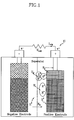
- FIG. 1 is a circuit diagram of a battery
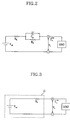
- FIG. 2 is a circuit diagram of an equivalent electric circuit for the battery of FIG. 1 ;
- FIG. 3 is a circuit diagram of an equivalent electric circuit of the battery of FIG. 1 in a steady state
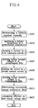
- FIG. 4 is a flowchart of a method of determining equivalent charge resistance data and effective no load charge voltage data in the method for determining a steady state battery terminal voltage according to the embodiment of the present invention
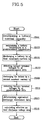
- FIG. 5 is a flowchart of a method for determining equivalent discharge resistance data and effective no load discharge voltage data in the method for determining a steady state battery terminal voltage according to the embodiment of the present invention
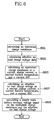
- FIG. 6 is a flowchart of a method for determining a steady state battery terminal voltage while a battery is being charged according to the embodiment of the present invention
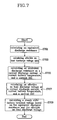
- FIG. 7 is a flowchart of a method for determining a steady state battery terminal voltage while a battery is being discharged according to the embodiment of the present invention
- FIGS. 8 to 15 are two-dimensional graphs showing the equivalent charge resistance data and the effective no load charge voltage for various charge currents
- FIGS. 16 to 23 are two-dimensional graphs showing the equivalent discharge resistance data and the effective no load discharge voltage for various discharge currents
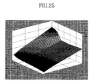
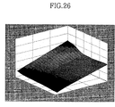
- FIGS. 24 to 26 are three-dimensional graphs showing steady state battery terminal voltages while a battery is being charged
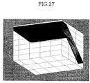
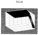
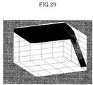
- FIGS. 27 to 29 are three-dimensional graphs showing steady state battery terminal voltages while a battery is being discharged
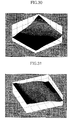
- FIG. 30 is a three-dimensional graph showing steady state battery terminal voltages with respect to changes of a battery temperature while a battery is being charged.
- FIG. 31 is a three-dimensional graph showing steady state battery terminal voltages with respect to changes of a battery temperature while a battery is being discharged.
- a method for calculating a steady state battery terminal voltage uses a steady state battery equivalent circuit as shown in FIG. 3 .
- the steady state battery terminal voltage V t can be calculated by the following equation 3.
- V t V oc ⁇ I t ⁇ R e [Equation 3] , where V oc is an effective no load charge voltage (or an effective no load discharge voltage), It is a charge current (or a discharge current), and R e is an equivalent charge resistance (or an equivalent discharge resistance).
- V dch — t V dch — oc ⁇ I dch — t ⁇ R dch — e
- V dch — t the steady state battery terminal voltage
- V dch — oc the effective no load discharge voltage
- I dch — t the current discharge current
- R dch — e the equivalent discharge resistance
- a resistance of the battery is composed of a conductor resistance due to a positive terminal, a negative terminal, and a current collector, and an electrochemical resistance due to a chemical reaction according to a state of charge (SOC) or a depth of discharge (DOD) and an electrolyte.
- the electrochemical resistance has a specific value according to the SOC (or DOD) and a reaction temperature (e.g., a battery temperature).
- battery terminal voltages are detected at predetermined SOCs while charging (or discharging) the battery with different constant currents at predetermined battery temperatures. Then, the steady state equivalent charge resistance (or the steady state equivalent discharge resistance) are calculated based on the constant current value and the terminal voltage.
- an effective no load charge voltage (or an effective no load discharge voltage) is calculated on the basis of the equivalent charge resistance (or the equivalent discharge current) and a theoretical voltage-current equation.
- the steady state battery terminal voltage is calculated using equivalent charge resistance data (or equivalent discharge resistance) including equivalent charge resistances (or equivalent discharge resistances) that are determined by the above-stated method, and effective no load charge voltage data (or effective no load discharge voltage data) including effective no load charge voltages (or effective no load discharge voltages) that are determined by the above-stated method.
- step S 401 a battery nominal capacity AH is determined through a nominal capacity test of the battery 11 .
- a battery temperature is maintained at a predetermined temperature (step S 403 ).
- Battery characteristics change according to the battery temperature, so it is preferable that the equivalent charge resistance data and the effective no load charge voltage data are determined for at least two battery temperatures.
- the predetermined battery temperature includes 0° C., 25° C., and 40° C.
- the predetermined battery temperature can be changed according to the type of a battery used.
- the predetermined battery temperature is selected to minimize errors by a non-linearity of characteristics of electrochemical reactions of the battery according to battery temperature.
- the equivalent charge resistance changes according to a level of a charge current, so it is preferable that the equivalent charge resistance data is determined for at least two predetermined charge current ranges.
- the predetermined charge current ranges include three ranges.
- the predetermined charge current ranges can include a range where the charge current is less than 1 C, a range where the charge current is between 1 C and 5 C, and a range where the charge current is greater than 5 C.
- the predetermined charge current ranges include a range where the charge current is less than 1 C and a range where the charge current is equal to or greater than 1 C.
- the predetermined charge current range can be changed according to specific battery characteristics. In some embodiments, the charge current ranges are determined to minimize errors by a nonlinearity of the electrochemical reaction of the battery.
- the current value 1 C indicates an amount of a current that charges or discharges to or from the nominal capacity of the battery in one hour.
- step S 405 in a state that the battery temperature is maintained at the predetermined temperature, the battery 11 is charged by a first constant current I 1 that belongs to the predetermined charge current range. While the battery 11 is being charged by the first constant current, first battery terminal voltages V 1 are detected at predetermined states of charge (SOCs), in step S 407 .
- SOCs states of charge
- the battery terminal voltage is detected when the SOC is 10%, 20%, 30%, 40%, 50%, 60%, 70%, 80%, and 90%.
- step S 409 while the battery temperature is being maintained at the predetermined temperature, the battery is charged by a second constant current I 2 that belongs to the predetermined charge current range. Then, in step S 411 , while the battery 11 is being charged by the second constant current, second battery terminal voltages are detected at predetermined SOCs.
- the equivalent charge resistance data is determined based on the first battery terminal voltages and the second battery terminal voltages.
- steps S 405 to S 415 are repeatedly performed using constant currents belonging to each of the charge current ranges while the battery temperature is being maintained at the predetermined temperature, the equivalent charge resistance data and the effective no load charge voltage data for the predetermined battery temperature are calculated.
- the equivalent charge resistance data and the effective no load charge voltage data are determined for each of the predetermined battery temperatures.
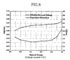
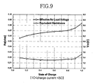
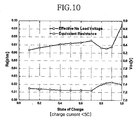
- FIGS. 8 to 15 show the equivalent charge resistance data and the effective no load charge voltage data for a specific battery, i.e., Panasonic EV Energy® Ni—MH 6.5AH.
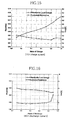
- the equivalent charge resistance data and the effective no load charge voltage data for the predetermined battery temperature of 25° C. are shown in FIGS. 8 to 10
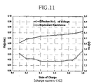
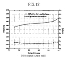
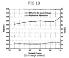
- the equivalent charge resistance data and the effective no load charge voltage data for the predetermined battery temperature of 40° C. are shown in FIGS. 11 to 13
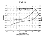
- the equivalent charge resistance data and the effective no load charge voltage data for the predetermined battery temperature of 0° C. are shown in FIGS. 14 and 15 .
- FIG. 8 the equivalent charge resistances and the effective no load voltages at each of the predetermined SOC levels when the predetermined battery temperature is 25° C. and the charge current is less than 1 C (e.g., each of the first and second constant currents is less than 1 C) are shown.
- FIG. 12 the equivalent charge resistances and the effective no load voltages at each of the predetermined SOC levels when the predetermined battery temperature is 40° C. and the charge current is between 1 C and 5 C (e.g., each of the first and second constant currents is between 1 C and 5 C) are shown.
- the equivalent charge resistance and the effective no load charge voltage changes according to the battery temperature, the SOC, and the charge current.
- the equivalent charge resistance generally increases with an increase of the SOC.
- the effective no load charge voltage is calculated by the above-stated equation 5.
- a battery nominal capacity AH is determined through a nominal capacity test for the battery 11 .
- a battery temperature is maintained at a predetermined temperature (step S 503 ).
- the equivalent discharge resistance data and the effective no load discharge voltage data are determined at predetermined battery temperatures and for predetermined discharge current ranges.
- the predetermined battery temperatures include 0° C., 25° C., and 40° C.
- the predetermined battery temperature can be changed according to type of battery.
- the predetermined battery temperature is selected to minimize errors by a non-linearity of characteristics of electrochemical reactions of the battery according to a battery temperature.
- the equivalent discharge resistance changes according to a level of a discharge current, so in some embodiments the equivalent discharge resistance data is determined for at least two predetermined discharge current ranges.
- the predetermined discharge current ranges include three ranges. That is, the predetermined discharge current ranges include a range where the discharge current is less than 1 C, a range where the discharge current is between 1 C and 5 C, and a range where the discharge current is greater than 5 C. However, in the case when the battery temperature is 0° C., the predetermined discharge current ranges include a range where the discharge current is less than 1 C and a range where the discharge current is equal to or greater than 1 C.
- the discharge current ranges are determined to minimize errors by a nonlinearity of the electrochemical reaction of the battery.
- step S 505 in a state that the battery temperature is maintained at the predetermined temperature, the battery 11 is discharged by a first constant current I 1 , that belongs to the predetermined discharge current range.
- first battery terminal voltages are detected at predetermined degrees of discharge (DODs), in step S 507 .
- the DOD (%) can be calculated by “100 ⁇ SOC”.
- the battery terminal voltage is detected at each of 10%, 20%, 30%, 40%, 50%, 60%, 70%, 80%, and 90%.
- step S 509 while the battery temperature is being maintained at the predetermined temperature, the battery is discharged by a second constant current I 2 that belongs to the predetermined discharge current range.
- step S 511 while the battery 11 is being discharged by the second constant current, second battery terminal voltages are detected at predetermined DODs.
- step S 513 the equivalent discharge resistance data is determined based on the first battery terminal voltages and the second battery terminal voltages.
- step S 515 the effective no load discharge voltage data is calculated based on the determined equivalent discharge resistance data.
- steps S 505 to S 515 are repeatedly performed using constant currents belonging to each of the discharge current ranges while the battery temperature is being maintained at the predetermined temperature, the equivalent discharge resistance data and the effective no load discharge voltage data for the predetermined battery temperature are calculated.
- the equivalent discharge resistance data and the effective no load discharge voltage data are determined for each of the predetermined battery temperatures.
- FIGS. 16 to 23 show the equivalent discharge resistance data and the effective no load discharge voltage data for a specific battery, i.e., Panasonic EV Energy® Ni—MH 6.5AH.
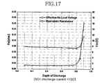
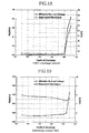
- the equivalent discharge resistance data and the effective no load discharge voltage data for the predetermined battery temperature of 25° C. are shown in FIGS. 16 to 18
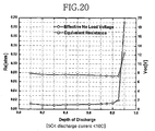
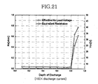
- the equivalent discharge resistance data and the effective no load discharge voltage data for the predetermined battery temperature of 40° C. are shown in FIGS. 19 to 21
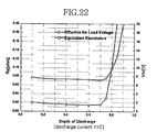
- the equivalent discharge resistance data and the effective no load discharge voltage data for the predetermined battery temperature of 0° C. are shown in FIGS. 22 and 23 .
- the equivalent discharge resistance and the effective no load discharge voltage change according to the battery temperature, the DOD, and the discharge current.
- the equivalent discharge resistance generally increases with an increase of the DOD.
- the effective no load discharge voltage is calculated by the above-stated equation 7.
- steps S 601 and S 603 the equivalent charge resistance data and the effective no load charge voltage data are calculated.
- step S 605 an equivalent charge resistance at current conditions (e.g., at a current charge current, a current battery temperature, and a current SOC) is calculated based on the determined equivalent charge resistance data.
- an equivalent charge resistance at current conditions e.g., at a current charge current, a current battery temperature, and a current SOC
- the equivalent charge resistance is calculated based on the equivalent charge resistance data of the specific charge current range to which the current charge current belongs.
- the equivalent charge resistance is calculated.
- the equivalent charge resistance at the current conditions can be calculated through an interpolation method with respect to the SOC and the battery temperature.
- an equivalent charge resistance is determined using the equivalent charge resistance data shown in FIGS. 9 and 12 .
- an equivalent charge resistance is determined using the equivalent charge resistance data shown in FIGS. 9 and 12 .
- an equivalent charge resistance corresponding to a case where the battery temperature is 25° C. and the SOC is 0.45 can be found.
- an equivalent charge resistance corresponding to a case where the battery temperature is 40° C. and the SOC is 0.45 can be found.
- an equivalent charge resistance corresponding to a case where the battery temperature is 30° C. and the SOC is 0.45 can be found.
- step S 607 an effective no load charge voltage at current conditions (e.g., at a current charge current, a current battery temperature, and a current SOC) is calculated based on the determined effective no load charge voltage data.
- current conditions e.g., at a current charge current, a current battery temperature, and a current SOC
- the effective no load charge voltage can be determined in a similar way with the equivalent charge resistance. That is, the effective no load charge voltage is calculated using the effective no load charge voltage data of a specific charge current range to which the current charge current belongs.
- the effective no load charge voltage is calculated.
- the effective no load charge voltage at the current conditions can be calculated through an interpolation method with respect to the SOC and the battery temperature.
- step S 609 the steady state battery terminal voltage is calculated based on the determined equivalent charge resistance and the determined effective no load charge voltage.
- step S 701 and S 703 the equivalent discharge resistance data and the effective no load discharge voltage data are calculated.
- the calculations of the equivalent discharge resistance and the effective no load discharge voltage data are already explained in reference to FIG. 5 .
- step S 705 an equivalent discharge resistance at current conditions (e.g., at a current discharge current, a current battery temperature, and a current DOD) is calculated based on the determined equivalent discharge resistance data.
- the equivalent discharge resistance is calculated based on the equivalent discharge resistance data of the specific discharge current range to which the current discharge current belongs.
- the equivalent discharge resistance is calculated.
- the equivalent discharge resistance at the current conditions can be calculated through an interpolation method with respect to the DOD and the battery temperature.
- step S 707 an effective no load discharge voltage at current conditions (e.g., at a current discharge current, a current battery temperature, and a current DOD) is calculated based on the determined effective no load discharge voltage data.
- current conditions e.g., at a current discharge current, a current battery temperature, and a current DOD
- the effective no load discharge voltage can be determined in a similar way with the equivalent discharge resistance. That is, the effective no load discharge voltage is calculated using the effective no load discharge voltage data of a specific discharge charge current range to which the current discharge charge current belongs.
- the effective no load discharge voltage is calculated.
- the effective no load discharge voltage at the current conditions can be calculated through an interpolation method with respect to the DOD and the battery temperature.
- step S 709 the steady state battery terminal voltage is calculated based on the determined equivalent discharge resistance and the determined effective no load discharge voltage.
- the steady state battery terminal voltage can be calculated.
- FIGS. 24 to 31 show the steady state battery terminal voltage determined by the embodiment of the present invention.
- FIGS. 24 to 26 show the steady state battery terminal voltage during the charge of the battery.
- FIG. 24 is for the case in which the battery temperature is 0° C.
- FIG. 25 is for the case in which the battery temperature is 25° C.
- FIG. 26 is for the case in which the battery temperature is 40° C.
- the battery terminal voltage increases as the SOC increases, and it decreases as the battery temperature increases.
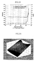
- FIGS. 27 to 29 show the steady state battery terminal voltage during the discharge of the battery.
- FIG. 27 is for the case in which the battery temperature is 0° C.
- FIG. 28 is for the case in which the battery temperature is 25° C.
- the FIG. 29 is for the case in which the battery temperature is 40° C.
- the battery terminal voltage decreases as the battery temperature decreases and the DOD increases.
- FIGS. 30 and 31 show changes of the battery terminal voltage according to a change of the battery temperature when the battery is charged or discharged at 1 C.
- the steady state battery terminal voltage at a current charge (or discharge) current, a current battery temperature, and a state of charge (or depth of discharge) can be determined using terminal voltages that are obtained while the battery is being charged (or discharged) by a constant current.
Abstract
Description
- This application claims priority of Korean Application No. 10-2003-0054720, filed on Aug. 7, 2003, the disclosure of which is incorporated fully herein by reference.
- The present invention relates to a method for calculating a steady state battery terminal voltage.
- A hybrid electric vehicle can improve the energy efficiency of an engine of a vehicle and decrease the amount of exhaust emissions of the engine. The improvements in energy efficiency for hybrid electric vehicles is due in part to the regeneration of electric energy from vehicle kinetic energy while the vehicle is being braked.
- A battery is an important part of a hybrid electric vehicle. The battery supplies power and stores remaining power. Unfortunately, the available power of the battery varies according to operating temperature, a state of charge (SOC), aging, or the like, thus making it is difficult to employ the battery in a hybrid electric vehicle.
- The terminal voltage of the battery increases as the battery charges, and it decreases as the battery discharges. In addition, the terminal voltage of the battery also changes according to charging/discharging load, so it is quite difficult to model battery terminal voltage characteristics.
- A battery cell terminal voltage Ucell of a battery cell in
FIG. 1 can be obtained according to the following equation 1:
, where Uocv is a no-load voltage (or a battery open-circuit voltage), Uc is a voltage variation due to load history, C is a capacitance, Iavg is an average current, Ud is a voltage drop due to dipoles (chemical activity) on the reactive surface, Ra is an electrolyte resistance, Rc is a conductor resistance, and TBAT is a battery temperature. The electrolyte resistance Ra changes according to an SOC, a battery temperature, and aging of the battery, and the conductor resistance Rc changes according to the aging of the battery. - In
FIG. 2 , an electric circuit that is equivalent to the battery cell ofFIG. 1 is shown. Based on this equivalent circuit, a terminal voltage Vt can be obtained according to the following equation 2:
, where Voc is an effective no load voltage, It is a charge (or discharge) current, Rh is an instantaneous resistance, Rd is a delayed resistance, and Cp is a parallel capacitance. The conductor resistance Rc contributed by the positive and negative terminals and a current collector can be expressed as the instantaneous resistance Rh. The electrolyte resistance is determined by Cp. - As can be observed from
Equation 2, a precise calculation of the battery terminal voltage Vt as a function of time using the battery equivalent model shown inFIG. 2 , is dependent upon knowledge of the capacitor value Cp. A precise capacitor value, however, is difficult to calculate because it changes according to load conditions and operating conditions. - Accordingly, what is needed is a method for determining a steady state battery terminal voltage under load and operating conditions.
- The disclosed embodiments of the present invention provide a method for calculating a steady state battery terminal voltage.
- In some embodiments of the present invention, the method for determining a steady state battery terminal voltage comprises: determining an equivalent charge resistance data at predetermined battery temperatures and predetermined states of charge (SOCs) for predetermined charge current ranges; determining effective no load charge voltage data at the predetermined battery temperatures and the predetermined SOCs for the predetermined charge current ranges on the basis of the equivalent charge resistance data; calculating an equivalent charge resistance at a current charge current, a current battery temperature, and a current SOC, based on the equivalent charge resistance data; calculating an effective no load charge voltage at the current charge current, the current battery temperature, and the current SOC, based on the effective no load charge voltage data; and calculating the steady state battery terminal voltage at the current charge current, the current battery temperature, and the current SOC, based on the calculated equivalent charge resistance and the calculated effective no load charge voltage.
- In some embodiments, the step of determining an equivalent charge resistance data comprises: detecting first battery terminal voltages at each of the predetermined SOCs while charging a battery at each of the predetermined battery temperatures with first constant charge currents belonging to each of the predetermined charge current ranges; detecting second battery terminal voltages at each of the predetermined SOCs while charging the battery at each of the predetermined battery temperatures with second constant charge currents belonging to each of the predetermined charge current ranges; and determining the equivalent charge resistance data at the predetermined battery temperatures and the predetermined SOCs for each of the predetermined charge current ranges, based on the first constant charge currents, the first battery terminal voltages, the second constant charge currents, and the second battery terminal voltages.
- In some embodiments, the equivalent charge resistance data Rcha
— e— data is calculated by the following equation:
, where I1 is the first constant charge current, I2 is the second constant charge current, V1 is the first battery terminal voltage, and V2 is the second battery terminal voltage. - In some embodiments, the effective no load charge voltage data Vcha
— oc— data is calculated by one of the following equations: - In some embodiments, an equivalent charge resistance, the equivalent charge resistance at the current charge current, the current battery temperature, and the current SOC are calculated based on the equivalent charge resistance data for the predetermined charge current range to which the current charge current belongs. In other embodiments, the equivalent charge resistance is calculated through interpolation.
- In some embodiments, an effective no load charge voltage, the effective no load charge voltage at the current charge current, the current battery temperature, and the current SOC are calculated based on the effective no load charge voltage data for the predetermined charge current range to which the current charge current belongs. In other embodiments, the effective no load charge voltage is calculated through interpolation.
- In some embodiments, the steady state battery terminal voltage Vcha
— t, the steady state battery terminal voltage at the current charge current, the battery temperature, and the current SOC are calculated by the following equation:
V cha— t =V cha— oc −I cha— t ×R cha— e
, where Vcha— oc is the effective no load charge voltage, Icha— t, is the current charge current, and Rcha— e is the equivalent charge resistance. - In some embodiments, the predetermined charge current ranges include a range where a charge current is less than 1 C, a range where the charge current is between 1 C and 5 C, and a range where the charge current is greater than 5 C.
- In some embodiments of the present invention, the method for determining a steady state battery terminal voltage, comprises: calculating an equivalent charge resistance at a current charge current, a current battery temperature, and a current state of charge (SOC), based on predetermined equivalent charge resistance data that is determined at predetermined battery temperatures and predetermined SOCs for predetermined charge current ranges; calculating an effective no load charge voltage at the current charge current, the current battery temperature, and the current SOC, based on predetermined effective no load charge voltage data that is determined at the predetermined battery temperatures and the predetermined SOCs for the predetermined charge current ranges; and calculating the steady state battery terminal voltage at the current charge current, the current battery temperature, and the current SOC, based on the calculated equivalent charge resistance and the calculated effective no load charge voltage.
- In some embodiments, the equivalent charge resistance is calculated based on the current battery temperature, the current SOC, and the equivalent charge resistance data for the predetermined current range to which the current charge current belongs. In other embodiments, the equivalent charge resistance is calculated through interpolation.
- In some embodiments, the effective no load charge voltage is calculated based on the current battery temperature, the current SOC, and the equivalent no load charge voltage data for the predetermined charge current range to which the current charge current belongs. In other embodiments, the effective no load charge voltage is calculated through interpolation.
- In some embodiments, the steady state battery terminal voltage is calculated by the following equation:
V cha— t =V cha— oc −I cha— t ×R cha— e
, where Vcha— oc is the effective no load charge voltage, Icha— t is the current charge current, and Rcha— e is the equivalent charge resistance. - In some embodiments of the present invention, the method for determining a steady state battery terminal voltage, comprises: determining equivalent discharge resistance data at predetermined battery temperatures and predetermined depths of discharge (DODs) for predetermined discharge current ranges; determining effective no load discharge voltage data at the predetermined battery temperatures and the predetermined DODs for the predetermined discharge current ranges on the basis of the equivalent discharge resistance data; calculating an equivalent discharge resistance at a current discharge current, a current battery temperature, and a current DOD, based on the equivalent discharge resistance data; calculating an effective no load discharge voltage at the current discharge current, the current battery temperature, and the current DOD, based on the effective no load discharge voltage data; and calculating the steady state battery terminal voltage at the current discharge current, the current battery temperature, and the current DOD, based on the calculated equivalent discharge resistance and the calculated effective no load discharge voltage.
- In some embodiments, the determining of an equivalent discharge resistance data comprises: detecting first battery terminal voltages at each of the predetermined DODs while discharging a battery at each of the predetermined battery temperatures with first constant discharge currents belonging to each of the predetermined discharge current ranges; detecting second battery terminal voltages at each of the predetermined DODs while discharging the battery at each of the predetermined battery temperatures with second constant discharge currents belonging to each of the predetermined discharge current ranges; and determining the equivalent discharge resistance data at the predetermined battery temperatures and the predetermined DODs for each of the predetermined discharge current ranges, based on the first constant discharge currents, the first battery terminal voltages, the second constant discharge currents, and the second battery terminal voltages.
- In some embodiments, the equivalent discharge resistance data Rdch
— e— data is calculated by the following equation:
, where I1 is the first constant discharge current, I2 is the second constant discharge current, V1 is the first battery terminal voltage, and V2 is the second battery terminal voltage. - In some embodiments, the effective no load discharge voltage data Vdch
— oc— data is calculated by one of the following equations: - In some embodiments, the equivalent discharge resistance at the current discharge current, the current battery temperature, and the current DOD are calculated based on the equivalent discharge resistance data for the predetermined discharge current range to which the current discharge current belongs. In other embodiments, the equivalent discharge resistance is calculated through interpolation.
- In some embodiments, the effective no load discharge voltage at the current discharge current, the current battery temperature, and the current DOD are calculated based on the effective no load discharge voltage data for the predetermined discharge current range to which the current discharge current belongs. In other embodiments, the effective no load discharge voltage is calculated through interpolation.
- In some embodiments, the steady state battery terminal voltage at the current discharge current, the battery temperature, and the current DOD is calculated by the following equation:
V dch— t =V dch— oc −I dch— t ×R dch— e
, where Vdch— oc is the effective no load discharge voltage, Idch— t is the current discharge current, and Rdch— e is the equivalent discharge resistance. - In some embodiments, The predetermined discharge current ranges include a range where a discharge current is less than 1 C, a range where the discharge current is between 1 C and 5 C, and a range where the discharge current is greater than 5 C.
- In some embodiments of the present invention, the method for determining a steady state battery terminal voltage comprises: calculating an equivalent discharge resistance at a current discharge current, a current battery temperature, and a current depth of discharge (DOD), based on predetermined equivalent discharge resistance data that are determined at predetermined battery temperatures and predetermined DODs for predetermined discharge current ranges; calculating an effective no load discharge voltage at the current discharge current, the current battery temperature, and the current DOD, based on predetermined effective no load discharge voltage data that are determined at the predetermined battery temperatures and the predetermined DODs for the predetermined discharge current ranges; and calculating the steady state battery terminal voltage at the current discharge current, the current battery temperature, and the current DOD, based on the calculated equivalent discharge resistance and the calculated effective no load discharge voltage.
- In some embodiments, the equivalent discharge resistance is calculated based on the current battery temperature, the current DOD, and the equivalent discharge resistance data for the predetermined current range to which the current discharge current belongs. In other embodiments, the equivalent discharge resistance is calculated through interpolation.
- In some embodiments, the effective no load discharge voltage is calculated based on the current battery temperature, the current DOD, and the equivalent no load discharge voltage data for the predetermined discharge current range to which the current discharge current belongs. In other embodiments, the effective no load discharge voltage is calculated through interpolation.
- In some embodiments, the steady state battery terminal voltage is calculated by the following equation:
V dch— t =V dch— oc −I dch— t ×R dch— e
, where Vdch— oc is the effective no load discharge voltage, Idch— t is the current discharge current, and Rdch— e is the equivalent discharge resistance. - The accompanying drawings, which are incorporated in and constitute a part of the specification, illustrate an embodiment of the invention, and, together with the description, serve to explain the principles of the invention, where:
-
FIG. 1 is a circuit diagram of a battery; -
FIG. 2 is a circuit diagram of an equivalent electric circuit for the battery ofFIG. 1 ; -
FIG. 3 is a circuit diagram of an equivalent electric circuit of the battery ofFIG. 1 in a steady state; -
FIG. 4 is a flowchart of a method of determining equivalent charge resistance data and effective no load charge voltage data in the method for determining a steady state battery terminal voltage according to the embodiment of the present invention; -
FIG. 5 is a flowchart of a method for determining equivalent discharge resistance data and effective no load discharge voltage data in the method for determining a steady state battery terminal voltage according to the embodiment of the present invention; -
FIG. 6 is a flowchart of a method for determining a steady state battery terminal voltage while a battery is being charged according to the embodiment of the present invention; -
FIG. 7 is a flowchart of a method for determining a steady state battery terminal voltage while a battery is being discharged according to the embodiment of the present invention; - FIGS. 8 to 15 are two-dimensional graphs showing the equivalent charge resistance data and the effective no load charge voltage for various charge currents;
- FIGS. 16 to 23 are two-dimensional graphs showing the equivalent discharge resistance data and the effective no load discharge voltage for various discharge currents;
- FIGS. 24 to 26 are three-dimensional graphs showing steady state battery terminal voltages while a battery is being charged;
- FIGS. 27 to 29 are three-dimensional graphs showing steady state battery terminal voltages while a battery is being discharged;
-
FIG. 30 is a three-dimensional graph showing steady state battery terminal voltages with respect to changes of a battery temperature while a battery is being charged; and -
FIG. 31 is a three-dimensional graph showing steady state battery terminal voltages with respect to changes of a battery temperature while a battery is being discharged. - Hereinafter, an embodiment of the present invention will be described in detail with reference to the accompanying drawings.
- A method for calculating a steady state battery terminal voltage according to an embodiment of the present invention uses a steady state battery equivalent circuit as shown in
FIG. 3 . The steady state battery terminal voltage Vt can be calculated by the following equation 3.
V t =V oc −I t ×R e [Equation 3]
, where Voc is an effective no load charge voltage (or an effective no load discharge voltage), It is a charge current (or a discharge current), and Re is an equivalent charge resistance (or an equivalent discharge resistance). - Equation 3 can be expressed as follows when the battery is charged:
V cha— t =V cha— oc −I cha— t ×R cha— e
, where Vcha— t is the steady state battery terminal voltage, Vcha— oc is the effective no load charge voltage, Icha— t is the current charge current, and Rcha— e is the equivalent charge resistance. - Similarly, the equation 3 can be expressed as follows when the battery is discharged:
V dch— t =V dch— oc −I dch— t ×R dch— e
, where Vdch— t is the steady state battery terminal voltage, Vdch— oc is the effective no load discharge voltage, Idch— t is the current discharge current, and Rdch— e is the equivalent discharge resistance. - A resistance of the battery is composed of a conductor resistance due to a positive terminal, a negative terminal, and a current collector, and an electrochemical resistance due to a chemical reaction according to a state of charge (SOC) or a depth of discharge (DOD) and an electrolyte. The electrochemical resistance has a specific value according to the SOC (or DOD) and a reaction temperature (e.g., a battery temperature).
- In the method for calculating the steady state battery terminal voltage according to an embodiment of the present invention, battery terminal voltages are detected at predetermined SOCs while charging (or discharging) the battery with different constant currents at predetermined battery temperatures. Then, the steady state equivalent charge resistance (or the steady state equivalent discharge resistance) are calculated based on the constant current value and the terminal voltage.
- Further, in the method for calculating the steady state battery terminal voltage according to an embodiment of the present invention, an effective no load charge voltage (or an effective no load discharge voltage) is calculated on the basis of the equivalent charge resistance (or the equivalent discharge current) and a theoretical voltage-current equation.
- In the method for calculating the steady state battery terminal voltage according an embodiment of the present invention, the steady state battery terminal voltage is calculated using equivalent charge resistance data (or equivalent discharge resistance) including equivalent charge resistances (or equivalent discharge resistances) that are determined by the above-stated method, and effective no load charge voltage data (or effective no load discharge voltage data) including effective no load charge voltages (or effective no load discharge voltages) that are determined by the above-stated method.
- Referring to
FIG. 4 , a process for determining the equivalent charge resistance data and the effective no load charge voltage will be explained. - In step S401, a battery nominal capacity AH is determined through a nominal capacity test of the
battery 11. - A battery temperature is maintained at a predetermined temperature (step S403). Battery characteristics change according to the battery temperature, so it is preferable that the equivalent charge resistance data and the effective no load charge voltage data are determined for at least two battery temperatures. In some embodiments of the present invention, the predetermined battery temperature includes 0° C., 25° C., and 40° C. The predetermined battery temperature can be changed according to the type of a battery used. In some embodiments, the predetermined battery temperature is selected to minimize errors by a non-linearity of characteristics of electrochemical reactions of the battery according to battery temperature.
- Furthermore, the equivalent charge resistance changes according to a level of a charge current, so it is preferable that the equivalent charge resistance data is determined for at least two predetermined charge current ranges. In some embodiments, the predetermined charge current ranges include three ranges. For example, the predetermined charge current ranges can include a range where the charge current is less than 1 C, a range where the charge current is between 1 C and 5 C, and a range where the charge current is greater than 5 C. However, in the case when the battery temperature is 0° C., the predetermined charge current ranges include a range where the charge current is less than 1 C and a range where the charge current is equal to or greater than 1 C.
- The predetermined charge current range can be changed according to specific battery characteristics. In some embodiments, the charge current ranges are determined to minimize errors by a nonlinearity of the electrochemical reaction of the battery. The current value 1 C indicates an amount of a current that charges or discharges to or from the nominal capacity of the battery in one hour.
- In step S405, in a state that the battery temperature is maintained at the predetermined temperature, the
battery 11 is charged by a first constant current I1 that belongs to the predetermined charge current range. While thebattery 11 is being charged by the first constant current, first battery terminal voltages V1 are detected at predetermined states of charge (SOCs), in step S407. For example, the battery terminal voltage is detected when the SOC is 10%, 20%, 30%, 40%, 50%, 60%, 70%, 80%, and 90%. - In step S409, while the battery temperature is being maintained at the predetermined temperature, the battery is charged by a second constant current I2 that belongs to the predetermined charge current range. Then, in step S411, while the
battery 11 is being charged by the second constant current, second battery terminal voltages are detected at predetermined SOCs. - Then, in step S413, the equivalent charge resistance data is determined based on the first battery terminal voltages and the second battery terminal voltages. The equivalent charge resistance data Rcha
— e— data includes equivalent charge resistances that are calculated for each of the predetermined SOCs, and they can be determined by the following equation 4:
, where “@SOC” means that the equivalent charge resistance is calculated at each of the SOC levels. - Then, in step S415, the effective no load charge voltage data is calculated based on the determined equivalent charge resistance data. The effective no load charge voltage data Vcha
— oc— data includes the effective no load charge voltages that are calculated at each of the SOC levels, and they can be calculated by the following equation 5:
, where “@SOC” means that the effective no load charge voltages are calculated at each of the SOC levels. - If the steps S405 to S415 are repeatedly performed using constant currents belonging to each of the charge current ranges while the battery temperature is being maintained at the predetermined temperature, the equivalent charge resistance data and the effective no load charge voltage data for the predetermined battery temperature are calculated.
- Further, if the steps S403 to S415 are repeatedly performed for each of the predetermined battery temperatures, the equivalent charge resistance data and the effective no load charge voltage data are determined for each of the predetermined battery temperatures.
- FIGS. 8 to 15 show the equivalent charge resistance data and the effective no load charge voltage data for a specific battery, i.e., Panasonic EV Energy® Ni—MH 6.5AH.
- The equivalent charge resistance data and the effective no load charge voltage data for the predetermined battery temperature of 25° C. are shown in FIGS. 8 to 10, the equivalent charge resistance data and the effective no load charge voltage data for the predetermined battery temperature of 40° C. are shown in FIGS. 11 to 13, and the equivalent charge resistance data and the effective no load charge voltage data for the predetermined battery temperature of 0° C. are shown in
FIGS. 14 and 15 . - In
FIG. 8 , the equivalent charge resistances and the effective no load voltages at each of the predetermined SOC levels when the predetermined battery temperature is 25° C. and the charge current is less than 1 C (e.g., each of the first and second constant currents is less than 1 C) are shown. - In
FIG. 9 , the equivalent charge resistances and the effective no load voltages at each of the predetermined SOC levels when the predetermined battery temperature is 25° C. and the charge current is between 1 C and 5 C (e.g., each of the first and second constant currents is between 1 C and 5 C) are shown. - In
FIG. 10 , the equivalent charge resistances and the effective no load voltages at each of the predetermined SOC levels when the predetermined battery temperature is 25° C. and the charge current is greater than 5 C (e.g., each of the first and second constant currents is greater than 5 C) are shown. - In
FIG. 11 , the equivalent charge resistances and the effective no load voltages at each of the predetermined SOC levels when the predetermined battery temperature is 40° C. and the charge current is less than 1 C (e.g., each of the first and second constant currents is less than 1 C) are shown. - In
FIG. 12 , the equivalent charge resistances and the effective no load voltages at each of the predetermined SOC levels when the predetermined battery temperature is 40° C. and the charge current is between 1 C and 5 C (e.g., each of the first and second constant currents is between 1 C and 5 C) are shown. - In
FIG. 13 , the equivalent charge resistances and the effective no load voltages at each of the predetermined SOC levels when the predetermined battery temperature is 40° C. and the charge current is greater than 5 C (e.g., each of the first and second constant currents is greater than 5 C) are shown. - In
FIG. 14 , the equivalent charge resistances and the effective no load voltages at each of the predetermined SOC levels when the predetermined battery temperature is 0° C. and the charge current is less than 1 C (e.g., each of the first and second constant currents is less than 1 C) are shown. - In
FIG. 15 , the equivalent charge resistances and the effective no load voltages at each of the predetermined SOC levels when the predetermined battery temperature is 0° C. and the charge current is greater than 1 C (e.g., each of the first and second constant currents is greater than 1 C) are shown. - As shown in FIGS. 8 to 15, the equivalent charge resistance and the effective no load charge voltage changes according to the battery temperature, the SOC, and the charge current.
- As shown in the drawings, the equivalent charge resistance generally increases with an increase of the SOC. The effective no load charge voltage is calculated by the above-stated
equation 5. - Referring to
FIG. 5 , a process for determining the equivalent discharge resistance data and the effective no load charge voltage will be explained. - At first, in step S501, a battery nominal capacity AH is determined through a nominal capacity test for the
battery 11. - A battery temperature is maintained at a predetermined temperature (step S503).
- Similar with the charge of the battery, it is preferable that the equivalent discharge resistance data and the effective no load discharge voltage data are determined at predetermined battery temperatures and for predetermined discharge current ranges.
- In this embodiment, the predetermined battery temperatures include 0° C., 25° C., and 40° C. The predetermined battery temperature can be changed according to type of battery.
- It some embodiments, the predetermined battery temperature is selected to minimize errors by a non-linearity of characteristics of electrochemical reactions of the battery according to a battery temperature.
- Furthermore, the equivalent discharge resistance changes according to a level of a discharge current, so in some embodiments the equivalent discharge resistance data is determined for at least two predetermined discharge current ranges.
- In this embodiment, the predetermined discharge current ranges include three ranges. That is, the predetermined discharge current ranges include a range where the discharge current is less than 1 C, a range where the discharge current is between 1 C and 5 C, and a range where the discharge current is greater than 5 C. However, in the case when the battery temperature is 0° C., the predetermined discharge current ranges include a range where the discharge current is less than 1 C and a range where the discharge current is equal to or greater than 1 C.
- It is preferable that the discharge current ranges are determined to minimize errors by a nonlinearity of the electrochemical reaction of the battery.
- In step S505, in a state that the battery temperature is maintained at the predetermined temperature, the
battery 11 is discharged by a first constant current I1, that belongs to the predetermined discharge current range. - While the
battery 11 is being discharged by the first constant current, first battery terminal voltages are detected at predetermined degrees of discharge (DODs), in step S507. The DOD (%) can be calculated by “100−SOC”. For example, the battery terminal voltage is detected at each of 10%, 20%, 30%, 40%, 50%, 60%, 70%, 80%, and 90%. - In step S509, while the battery temperature is being maintained at the predetermined temperature, the battery is discharged by a second constant current I2 that belongs to the predetermined discharge current range.
- Then, in step S511, while the
battery 11 is being discharged by the second constant current, second battery terminal voltages are detected at predetermined DODs. - Then, in step S513, the equivalent discharge resistance data is determined based on the first battery terminal voltages and the second battery terminal voltages.
- The equivalent discharge resistance data Rdch
— e— data includes equivalent discharge resistances that are calculated for each of the predetermined DODs, and they can be determined the following equation 6:
, where “@DOD” means that the equivalent discharge resistance is calculated at each of the DOD levels. - Then, in step S515, the effective no load discharge voltage data is calculated based on the determined equivalent discharge resistance data.
- The effective no load discharge voltage data Vdch
— oc— data includes the effective no load discharge voltages that are calculated at each of the DOD levels, and they can be calculated by the following equation 7:
, where “@DOD” means that the effective no load discharge voltages are calculated at each of the DOD levels. - If the steps S505 to S515 are repeatedly performed using constant currents belonging to each of the discharge current ranges while the battery temperature is being maintained at the predetermined temperature, the equivalent discharge resistance data and the effective no load discharge voltage data for the predetermined battery temperature are calculated.
- Further, if the steps S503 to S515 are repeatedly performed for each of the predetermined battery temperatures, the equivalent discharge resistance data and the effective no load discharge voltage data are determined for each of the predetermined battery temperatures.
- FIGS. 16 to 23 show the equivalent discharge resistance data and the effective no load discharge voltage data for a specific battery, i.e., Panasonic EV Energy® Ni—MH 6.5AH.
- The equivalent discharge resistance data and the effective no load discharge voltage data for the predetermined battery temperature of 25° C. are shown in FIGS. 16 to 18, the equivalent discharge resistance data and the effective no load discharge voltage data for the predetermined battery temperature of 40° C. are shown in FIGS. 19 to 21, and the equivalent discharge resistance data and the effective no load discharge voltage data for the predetermined battery temperature of 0° C. are shown in
FIGS. 22 and 23 . - As shown in FIGS. 16 to 23, the equivalent discharge resistance and the effective no load discharge voltage change according to the battery temperature, the DOD, and the discharge current.
- As shown in the drawings, the equivalent discharge resistance generally increases with an increase of the DOD. The effective no load discharge voltage is calculated by the above-stated equation 7.
- Referring to
FIG. 6 , the method for calculating the steady state battery terminal voltage while the battery is being charged will be explained. - At first, in steps S601 and S603, the equivalent charge resistance data and the effective no load charge voltage data are calculated.
- The calculations of the equivalent charge resistance and the effective no load charge voltage data are already explained referring to
FIG. 4 . - Then, in step S605, an equivalent charge resistance at current conditions (e.g., at a current charge current, a current battery temperature, and a current SOC) is calculated based on the determined equivalent charge resistance data.
- At this time, the equivalent charge resistance is calculated based on the equivalent charge resistance data of the specific charge current range to which the current charge current belongs.
- Then, using the corresponding equivalent charge resistance data, the equivalent charge resistance is calculated. At this time, the equivalent charge resistance at the current conditions can be calculated through an interpolation method with respect to the SOC and the battery temperature.
- For example, if a current charge current is 3 C, a current SOC is 0.45 (e.g., 45%), and a current battery temperature is 30° C., an equivalent charge resistance is determined using the equivalent charge resistance data shown in
FIGS. 9 and 12 . By performing interpolation with respect to the SOC using equivalent charge resistances corresponding to SOC 0.4 and SOC 0.5, an equivalent charge resistance corresponding to a case where the battery temperature is 25° C. and the SOC is 0.45 can be found. Similarly, by performing interpolation with respect to the SOC using equivalent charge resistances corresponding to SOC 0.4 and SOC 0.5, an equivalent charge resistance corresponding to a case where the battery temperature is 40° C. and the SOC is 0.45 can be found. Then, by performing interpolation with respect to the battery temperature using the two equivalent charge resistances, an equivalent charge resistance corresponding to a case where the battery temperature is 30° C. and the SOC is 0.45 can be found. - In step S607, an effective no load charge voltage at current conditions (e.g., at a current charge current, a current battery temperature, and a current SOC) is calculated based on the determined effective no load charge voltage data.
- The effective no load charge voltage can be determined in a similar way with the equivalent charge resistance. That is, the effective no load charge voltage is calculated using the effective no load charge voltage data of a specific charge current range to which the current charge current belongs.
- Then, using the corresponding effective no load charge voltage data, the effective no load charge voltage is calculated. At this time, the effective no load charge voltage at the current conditions can be calculated through an interpolation method with respect to the SOC and the battery temperature.
- Then, in step S609, the steady state battery terminal voltage is calculated based on the determined equivalent charge resistance and the determined effective no load charge voltage.
- At this time, by inserting the equivalent charge resistance Rcha
— e, the effective no load charge voltage Vcha— oc and the current charge current Icha— t into the equation 3, the steady state battery terminal voltage can be calculated. - Referring to
FIG. 7 , the method for calculating the steady state battery terminal voltage while the battery is being discharged will be explained. - At first, in step S701 and S703, the equivalent discharge resistance data and the effective no load discharge voltage data are calculated. The calculations of the equivalent discharge resistance and the effective no load discharge voltage data are already explained in reference to
FIG. 5 . - Then, in step S705, an equivalent discharge resistance at current conditions (e.g., at a current discharge current, a current battery temperature, and a current DOD) is calculated based on the determined equivalent discharge resistance data. At this time, the equivalent discharge resistance is calculated based on the equivalent discharge resistance data of the specific discharge current range to which the current discharge current belongs.
- Then, using the corresponding equivalent discharge resistance data, the equivalent discharge resistance is calculated. At this time, the equivalent discharge resistance at the current conditions can be calculated through an interpolation method with respect to the DOD and the battery temperature.
- Because the calculation of the equivalent discharge resistance through the interpolation method can be performed similarly with the calculation of the equivalent charge resistance using the interpolation method, further explanations will be omitted.
- In step S707, an effective no load discharge voltage at current conditions (e.g., at a current discharge current, a current battery temperature, and a current DOD) is calculated based on the determined effective no load discharge voltage data.
- The effective no load discharge voltage can be determined in a similar way with the equivalent discharge resistance. That is, the effective no load discharge voltage is calculated using the effective no load discharge voltage data of a specific discharge charge current range to which the current discharge charge current belongs.
- Then, using the corresponding effective no load discharge voltage data, the effective no load discharge voltage is calculated. At this time, the effective no load discharge voltage at the current conditions can be calculated through an interpolation method with respect to the DOD and the battery temperature.
- Then, in step S709, the steady state battery terminal voltage is calculated based on the determined equivalent discharge resistance and the determined effective no load discharge voltage.
- At this time, by inserting the equivalent discharge resistance Rdch
— e, the effective no load discharge voltage Vdch— oc, and the current discharge current Idch— t into the equation 3, the steady state battery terminal voltage can be calculated. - FIGS. 24 to 31 show the steady state battery terminal voltage determined by the embodiment of the present invention.
- FIGS. 24 to 26 show the steady state battery terminal voltage during the charge of the battery.
FIG. 24 is for the case in which the battery temperature is 0° C.,FIG. 25 is for the case in which the battery temperature is 25° C., andFIG. 26 is for the case in which the battery temperature is 40° C. - As shown in FIGS. 24 to 26, the battery terminal voltage increases as the SOC increases, and it decreases as the battery temperature increases.
- FIGS. 27 to 29 show the steady state battery terminal voltage during the discharge of the battery.
FIG. 27 is for the case in which the battery temperature is 0° C.,FIG. 28 is for the case in which the battery temperature is 25° C., and theFIG. 29 is for the case in which the battery temperature is 40° C. - As shown in FIGS. 27 to 29, the battery terminal voltage decreases as the battery temperature decreases and the DOD increases.
-
FIGS. 30 and 31 show changes of the battery terminal voltage according to a change of the battery temperature when the battery is charged or discharged at 1 C. - Although preferred embodiments of the present invention have been described in detail hereinabove, it should be clearly understood that many variations and/or modifications of the basic inventive concepts herein taught which may appear to those skilled in the present art will still fall within the spirit and scope of the present invention, as defined in the appended claims.
- According to the embodiment of the present invention, the steady state battery terminal voltage at a current charge (or discharge) current, a current battery temperature, and a state of charge (or depth of discharge) can be determined using terminal voltages that are obtained while the battery is being charged (or discharged) by a constant current.
Claims (32)
V cha
V cha
V dch
V dch
Applications Claiming Priority (2)
| Application Number | Priority Date | Filing Date | Title |
|---|---|---|---|
| KR10-2003-0054720A KR100494947B1 (en) | 2003-08-07 | 2003-08-07 | A method for calculating a steady state battery terminal voltage |
| KR10-2003-0054720 | 2003-08-07 |
Publications (2)
| Publication Number | Publication Date |
|---|---|
| US20050030041A1 true US20050030041A1 (en) | 2005-02-10 |
| US7078878B2 US7078878B2 (en) | 2006-07-18 |
Family
ID=34114294
Family Applications (1)
| Application Number | Title | Priority Date | Filing Date |
|---|---|---|---|
| US10/750,690 Active 2024-06-03 US7078878B2 (en) | 2003-08-07 | 2003-12-31 | Method for determining a steady state battery terminal voltage |
Country Status (5)
| Country | Link |
|---|---|
| US (1) | US7078878B2 (en) |
| JP (1) | JP3876252B2 (en) |
| KR (1) | KR100494947B1 (en) |
| CN (1) | CN1276264C (en) |
| DE (1) | DE10357984B4 (en) |
Cited By (5)
| Publication number | Priority date | Publication date | Assignee | Title |
|---|---|---|---|---|
| CN102810882A (en) * | 2011-06-02 | 2012-12-05 | 魏培伦 | Circuit and method for measuring battery voltage |
| EP2827162A1 (en) * | 2013-07-16 | 2015-01-21 | ST-Ericsson SA | Battery DC impedance measurement |
| US20150048838A1 (en) * | 2012-04-19 | 2015-02-19 | Toyota Jidosha Kabushiki Kaisha | Apparatus and method for inspecting all-solid battery |
| US20150362561A1 (en) * | 2014-06-11 | 2015-12-17 | GM Global Technology Operations LLC | Battery state of health estimation using charging resistance equivalent |
| CN107957560A (en) * | 2017-12-19 | 2018-04-24 | 国联汽车动力电池研究院有限责任公司 | A kind of lithium ion battery SOC algorithm for estimating based on equivalent circuit |
Families Citing this family (14)
| Publication number | Priority date | Publication date | Assignee | Title |
|---|---|---|---|---|
| US7612532B2 (en) * | 2005-06-21 | 2009-11-03 | Gm Global Technology Operations, Inc. | Method for controlling and monitoring using a state estimator having variable forgetting factors |
| KR100736995B1 (en) * | 2005-11-18 | 2007-07-09 | 현대자동차주식회사 | A method for calculation battery aging factor of hybrid vehicle |
| US9201121B2 (en) * | 2010-12-06 | 2015-12-01 | Texas Instruments Incorporated | System and method for sensing battery capacity |
| KR101526641B1 (en) * | 2011-12-08 | 2015-06-08 | 현대자동차주식회사 | Degradation estimation method for high voltage battery of vehicle |
| CN102955135B (en) * | 2012-11-20 | 2017-03-22 | 无锡中感微电子股份有限公司 | Method and system for detecting electric quantity of battery |
| CN102944847B (en) * | 2012-11-20 | 2016-02-03 | 无锡中感微电子股份有限公司 | Battery electricity detection method and system |
| JP6221237B2 (en) * | 2013-01-21 | 2017-11-01 | 株式会社豊田自動織機 | CHARGE RATE ESTIMATION DEVICE AND CHARGE RATE ESTIMATION METHOD |
| CN103197251B (en) * | 2013-02-27 | 2016-02-03 | 山东省科学院自动化研究所 | A kind of discrimination method of dynamic lithium battery Order RC equivalent model |
| KR102165937B1 (en) * | 2014-05-30 | 2020-10-14 | 삼성전자주식회사 | Method and apparatus for managing battery |
| KR102285148B1 (en) * | 2016-08-22 | 2021-08-04 | 삼성에스디아이 주식회사 | Battery charging method and battery charging apparatus using the same |
| KR102471976B1 (en) * | 2017-12-14 | 2022-11-29 | 에스케이온 주식회사 | Apparatus and method for regulating available current of battery |
| DE102019115739A1 (en) | 2018-06-28 | 2019-08-08 | FEV Europe GmbH | Method for determining an energy distribution |
| CN113447826B (en) * | 2021-09-01 | 2021-11-16 | 蜂巢能源科技有限公司 | SOC determination method and device based on steady-state equivalent circuit model |
| CN116685853A (en) * | 2021-11-09 | 2023-09-01 | 宁德时代新能源科技股份有限公司 | Method for determining direct current discharge resistance and maximum discharge power and battery management system |
Family Cites Families (5)
| Publication number | Priority date | Publication date | Assignee | Title |
|---|---|---|---|---|
| DE69030063T2 (en) * | 1989-12-11 | 1997-07-10 | Canon Kk | Battery residual charge determination arrangement |
| JP3607105B2 (en) * | 1999-01-26 | 2005-01-05 | 本田技研工業株式会社 | Battery remaining capacity detection device |
| JP2002236157A (en) | 2000-12-04 | 2002-08-23 | Yazaki Corp | Terminal voltage estimation method of battery and its device, open circuit voltage operation method of battery and its device, battery capacity operation method and its device |
| DE10161640A1 (en) * | 2001-12-14 | 2003-07-10 | Vb Autobatterie Gmbh | Method for determining the operating state of a storage battery |
| JP4097182B2 (en) | 2001-12-27 | 2008-06-11 | パナソニックEvエナジー株式会社 | Secondary battery polarization voltage estimation method, secondary battery remaining capacity estimation method and apparatus, and battery pack system |
-
2003
- 2003-08-07 KR KR10-2003-0054720A patent/KR100494947B1/en not_active IP Right Cessation
- 2003-12-11 DE DE10357984A patent/DE10357984B4/en not_active Expired - Fee Related
- 2003-12-22 JP JP2003425935A patent/JP3876252B2/en not_active Expired - Fee Related
- 2003-12-25 CN CNB2003101130521A patent/CN1276264C/en not_active Expired - Fee Related
- 2003-12-31 US US10/750,690 patent/US7078878B2/en active Active
Cited By (9)
| Publication number | Priority date | Publication date | Assignee | Title |
|---|---|---|---|---|
| CN102810882A (en) * | 2011-06-02 | 2012-12-05 | 魏培伦 | Circuit and method for measuring battery voltage |
| US20150048838A1 (en) * | 2012-04-19 | 2015-02-19 | Toyota Jidosha Kabushiki Kaisha | Apparatus and method for inspecting all-solid battery |
| US9903918B2 (en) * | 2012-04-19 | 2018-02-27 | Toyota Jidosha Kabushiki Kaisha | Apparatus and method for inspecting all-solid battery |
| EP2827162A1 (en) * | 2013-07-16 | 2015-01-21 | ST-Ericsson SA | Battery DC impedance measurement |
| US9841465B2 (en) | 2013-07-16 | 2017-12-12 | Stmicroelectronics International N.V. | Battery DC impedance measurement |
| US10191118B2 (en) | 2013-07-16 | 2019-01-29 | Stmicroelectronics International N.V. | Battery DC impedance measurement |
| US20150362561A1 (en) * | 2014-06-11 | 2015-12-17 | GM Global Technology Operations LLC | Battery state of health estimation using charging resistance equivalent |
| US10042006B2 (en) * | 2014-06-11 | 2018-08-07 | GM Global Technology Operations LLC | Battery state of health estimation using charging resistance equivalent |
| CN107957560A (en) * | 2017-12-19 | 2018-04-24 | 国联汽车动力电池研究院有限责任公司 | A kind of lithium ion battery SOC algorithm for estimating based on equivalent circuit |
Also Published As
| Publication number | Publication date |
|---|---|
| CN1276264C (en) | 2006-09-20 |
| DE10357984A1 (en) | 2005-03-10 |
| KR20050015767A (en) | 2005-02-21 |
| CN1581564A (en) | 2005-02-16 |
| US7078878B2 (en) | 2006-07-18 |
| DE10357984B4 (en) | 2007-02-08 |
| KR100494947B1 (en) | 2005-06-13 |
| JP3876252B2 (en) | 2007-01-31 |
| JP2005055420A (en) | 2005-03-03 |
Similar Documents
| Publication | Publication Date | Title |
|---|---|---|
| US7078878B2 (en) | Method for determining a steady state battery terminal voltage | |
| US6700383B2 (en) | Method of detecting and resolving memory effect | |
| US6646421B2 (en) | Method and apparatus for controlling residual battery capacity of secondary battery | |
| CN107710545B (en) | Method for predicting battery charge limit and method and apparatus for rapidly charging battery using the same | |
| EP2700966B1 (en) | Apparatus and method for estimating battery state | |
| US6300763B1 (en) | Method of calculating dynamic state-of-charge within a battery | |
| JP4759795B2 (en) | Rechargeable battery remaining capacity detection method | |
| JP3870577B2 (en) | Variation determination method for battery pack and battery device | |
| JP3387287B2 (en) | Regenerative charging control device | |
| Motloch et al. | High-power battery testing procedures and analytical methodologies for HEV's | |
| EP2957921B1 (en) | Method and system for estimating soc of battery | |
| CN104051810B (en) | A kind of lithium-ion energy storage battery system SOC estimates rapid correction method | |
| CN110061531B (en) | Energy storage battery equalization method | |
| KR101504804B1 (en) | Apparatus and method for estimating state of secondary battery considering aging | |
| US20140084939A1 (en) | Condition estimation device and method of generating open circuit voltage characteristic | |
| CN103267952B (en) | Method for measuring charging efficiency of power batteries | |
| KR20190070262A (en) | Secondary battery system and method of estimating stress of active material of secondary battery | |
| CN110320477B (en) | SOC (State of Charge) calculation method and device of power battery pack and electric automobile | |
| CN105634063A (en) | Battery historical data based active equalization method | |
| JP2012104239A (en) | Lithium ion battery electricity storage amount estimation method, lithium ion battery electricity storage amount estimation program, lithium ion battery electricity storage amount correction method, and lithium ion battery electricity storage amount correction program | |
| Kataoka et al. | Battery state estimation system for automobiles | |
| JP2003243042A (en) | Detecting method and device for degree of deterioration of lithium battery as component of package battery | |
| CN111551868B (en) | Consistency analysis method for lithium iron phosphate battery system | |
| CN109709490B (en) | Correction method for full life cycle SOC of lithium battery system | |
| CN113253137B (en) | Device and method for determining state of charge of battery pack |
Legal Events
| Date | Code | Title | Description |
|---|---|---|---|
| AS | Assignment |
Owner name: HYUNDAI MOTOR COMPANY, KOREA, REPUBLIC OF Free format text: ASSIGNMENT OF ASSIGNORS INTEREST;ASSIGNOR:KOO, JAE SEUNG;REEL/FRAME:014876/0630 Effective date: 20031224 |
|
| FEPP | Fee payment procedure |
Free format text: PAYOR NUMBER ASSIGNED (ORIGINAL EVENT CODE: ASPN); ENTITY STATUS OF PATENT OWNER: LARGE ENTITY |
|
| STCF | Information on status: patent grant |
Free format text: PATENTED CASE |
|
| FEPP | Fee payment procedure |
Free format text: PAYER NUMBER DE-ASSIGNED (ORIGINAL EVENT CODE: RMPN); ENTITY STATUS OF PATENT OWNER: LARGE ENTITY |
|
| FEPP | Fee payment procedure |
Free format text: PAYOR NUMBER ASSIGNED (ORIGINAL EVENT CODE: ASPN); ENTITY STATUS OF PATENT OWNER: LARGE ENTITY |
|
| FPAY | Fee payment |
Year of fee payment: 4 |
|
| FPAY | Fee payment |
Year of fee payment: 8 |
|
| MAFP | Maintenance fee payment |
Free format text: PAYMENT OF MAINTENANCE FEE, 12TH YEAR, LARGE ENTITY (ORIGINAL EVENT CODE: M1553) Year of fee payment: 12 |