JP6221237B2 - CHARGE RATE ESTIMATION DEVICE AND CHARGE RATE ESTIMATION METHOD - Google Patents
CHARGE RATE ESTIMATION DEVICE AND CHARGE RATE ESTIMATION METHOD Download PDFInfo
- Publication number
- JP6221237B2 JP6221237B2 JP2013008171A JP2013008171A JP6221237B2 JP 6221237 B2 JP6221237 B2 JP 6221237B2 JP 2013008171 A JP2013008171 A JP 2013008171A JP 2013008171 A JP2013008171 A JP 2013008171A JP 6221237 B2 JP6221237 B2 JP 6221237B2
- Authority
- JP
- Japan
- Prior art keywords
- charging
- circuit voltage
- battery
- closed circuit
- charging rate
- Prior art date
- Legal status (The legal status is an assumption and is not a legal conclusion. Google has not performed a legal analysis and makes no representation as to the accuracy of the status listed.)
- Expired - Fee Related
Links
Images

Classifications
-
- G—PHYSICS
- G01—MEASURING; TESTING
- G01R—MEASURING ELECTRIC VARIABLES; MEASURING MAGNETIC VARIABLES
- G01R31/00—Arrangements for testing electric properties; Arrangements for locating electric faults; Arrangements for electrical testing characterised by what is being tested not provided for elsewhere
- G01R31/36—Arrangements for testing, measuring or monitoring the electrical condition of accumulators or electric batteries, e.g. capacity or state of charge [SoC]
- G01R31/367—Software therefor, e.g. for battery testing using modelling or look-up tables
-
- B—PERFORMING OPERATIONS; TRANSPORTING
- B60—VEHICLES IN GENERAL
- B60L—PROPULSION OF ELECTRICALLY-PROPELLED VEHICLES; SUPPLYING ELECTRIC POWER FOR AUXILIARY EQUIPMENT OF ELECTRICALLY-PROPELLED VEHICLES; ELECTRODYNAMIC BRAKE SYSTEMS FOR VEHICLES IN GENERAL; MAGNETIC SUSPENSION OR LEVITATION FOR VEHICLES; MONITORING OPERATING VARIABLES OF ELECTRICALLY-PROPELLED VEHICLES; ELECTRIC SAFETY DEVICES FOR ELECTRICALLY-PROPELLED VEHICLES
- B60L3/00—Electric devices on electrically-propelled vehicles for safety purposes; Monitoring operating variables, e.g. speed, deceleration or energy consumption
- B60L3/12—Recording operating variables ; Monitoring of operating variables
-
- G—PHYSICS
- G01—MEASURING; TESTING
- G01R—MEASURING ELECTRIC VARIABLES; MEASURING MAGNETIC VARIABLES
- G01R31/00—Arrangements for testing electric properties; Arrangements for locating electric faults; Arrangements for electrical testing characterised by what is being tested not provided for elsewhere
- G01R31/36—Arrangements for testing, measuring or monitoring the electrical condition of accumulators or electric batteries, e.g. capacity or state of charge [SoC]
- G01R31/382—Arrangements for monitoring battery or accumulator variables, e.g. SoC
- G01R31/3835—Arrangements for monitoring battery or accumulator variables, e.g. SoC involving only voltage measurements
-
- G—PHYSICS
- G01—MEASURING; TESTING
- G01R—MEASURING ELECTRIC VARIABLES; MEASURING MAGNETIC VARIABLES
- G01R31/00—Arrangements for testing electric properties; Arrangements for locating electric faults; Arrangements for electrical testing characterised by what is being tested not provided for elsewhere
- G01R31/36—Arrangements for testing, measuring or monitoring the electrical condition of accumulators or electric batteries, e.g. capacity or state of charge [SoC]
- G01R31/385—Arrangements for measuring battery or accumulator variables
- G01R31/387—Determining ampere-hour charge capacity or SoC
- G01R31/388—Determining ampere-hour charge capacity or SoC involving voltage measurements
-
- H—ELECTRICITY
- H01—ELECTRIC ELEMENTS
- H01M—PROCESSES OR MEANS, e.g. BATTERIES, FOR THE DIRECT CONVERSION OF CHEMICAL ENERGY INTO ELECTRICAL ENERGY
- H01M10/00—Secondary cells; Manufacture thereof
- H01M10/42—Methods or arrangements for servicing or maintenance of secondary cells or secondary half-cells
- H01M10/48—Accumulators combined with arrangements for measuring, testing or indicating the condition of cells, e.g. the level or density of the electrolyte
-
- B—PERFORMING OPERATIONS; TRANSPORTING
- B60—VEHICLES IN GENERAL
- B60L—PROPULSION OF ELECTRICALLY-PROPELLED VEHICLES; SUPPLYING ELECTRIC POWER FOR AUXILIARY EQUIPMENT OF ELECTRICALLY-PROPELLED VEHICLES; ELECTRODYNAMIC BRAKE SYSTEMS FOR VEHICLES IN GENERAL; MAGNETIC SUSPENSION OR LEVITATION FOR VEHICLES; MONITORING OPERATING VARIABLES OF ELECTRICALLY-PROPELLED VEHICLES; ELECTRIC SAFETY DEVICES FOR ELECTRICALLY-PROPELLED VEHICLES
- B60L2240/00—Control parameters of input or output; Target parameters
- B60L2240/40—Drive Train control parameters
- B60L2240/54—Drive Train control parameters related to batteries
- B60L2240/547—Voltage
-
- B—PERFORMING OPERATIONS; TRANSPORTING
- B60—VEHICLES IN GENERAL
- B60L—PROPULSION OF ELECTRICALLY-PROPELLED VEHICLES; SUPPLYING ELECTRIC POWER FOR AUXILIARY EQUIPMENT OF ELECTRICALLY-PROPELLED VEHICLES; ELECTRODYNAMIC BRAKE SYSTEMS FOR VEHICLES IN GENERAL; MAGNETIC SUSPENSION OR LEVITATION FOR VEHICLES; MONITORING OPERATING VARIABLES OF ELECTRICALLY-PROPELLED VEHICLES; ELECTRIC SAFETY DEVICES FOR ELECTRICALLY-PROPELLED VEHICLES
- B60L2240/00—Control parameters of input or output; Target parameters
- B60L2240/40—Drive Train control parameters
- B60L2240/54—Drive Train control parameters related to batteries
- B60L2240/549—Current
-
- B—PERFORMING OPERATIONS; TRANSPORTING
- B60—VEHICLES IN GENERAL
- B60L—PROPULSION OF ELECTRICALLY-PROPELLED VEHICLES; SUPPLYING ELECTRIC POWER FOR AUXILIARY EQUIPMENT OF ELECTRICALLY-PROPELLED VEHICLES; ELECTRODYNAMIC BRAKE SYSTEMS FOR VEHICLES IN GENERAL; MAGNETIC SUSPENSION OR LEVITATION FOR VEHICLES; MONITORING OPERATING VARIABLES OF ELECTRICALLY-PROPELLED VEHICLES; ELECTRIC SAFETY DEVICES FOR ELECTRICALLY-PROPELLED VEHICLES
- B60L2260/00—Operating Modes
- B60L2260/40—Control modes
- B60L2260/44—Control modes by parameter estimation
-
- H—ELECTRICITY
- H01—ELECTRIC ELEMENTS
- H01M—PROCESSES OR MEANS, e.g. BATTERIES, FOR THE DIRECT CONVERSION OF CHEMICAL ENERGY INTO ELECTRICAL ENERGY
- H01M10/00—Secondary cells; Manufacture thereof
- H01M10/05—Accumulators with non-aqueous electrolyte
- H01M10/052—Li-accumulators
- H01M10/0525—Rocking-chair batteries, i.e. batteries with lithium insertion or intercalation in both electrodes; Lithium-ion batteries
-
- H—ELECTRICITY
- H01—ELECTRIC ELEMENTS
- H01M—PROCESSES OR MEANS, e.g. BATTERIES, FOR THE DIRECT CONVERSION OF CHEMICAL ENERGY INTO ELECTRICAL ENERGY
- H01M2220/00—Batteries for particular applications
- H01M2220/20—Batteries in motive systems, e.g. vehicle, ship, plane
-
- H—ELECTRICITY
- H01—ELECTRIC ELEMENTS
- H01M—PROCESSES OR MEANS, e.g. BATTERIES, FOR THE DIRECT CONVERSION OF CHEMICAL ENERGY INTO ELECTRICAL ENERGY
- H01M4/00—Electrodes
- H01M4/02—Electrodes composed of, or comprising, active material
- H01M4/36—Selection of substances as active materials, active masses, active liquids
- H01M4/48—Selection of substances as active materials, active masses, active liquids of inorganic oxides or hydroxides
- H01M4/483—Selection of substances as active materials, active masses, active liquids of inorganic oxides or hydroxides for non-aqueous cells
-
- Y—GENERAL TAGGING OF NEW TECHNOLOGICAL DEVELOPMENTS; GENERAL TAGGING OF CROSS-SECTIONAL TECHNOLOGIES SPANNING OVER SEVERAL SECTIONS OF THE IPC; TECHNICAL SUBJECTS COVERED BY FORMER USPC CROSS-REFERENCE ART COLLECTIONS [XRACs] AND DIGESTS
- Y02—TECHNOLOGIES OR APPLICATIONS FOR MITIGATION OR ADAPTATION AGAINST CLIMATE CHANGE
- Y02E—REDUCTION OF GREENHOUSE GAS [GHG] EMISSIONS, RELATED TO ENERGY GENERATION, TRANSMISSION OR DISTRIBUTION
- Y02E60/00—Enabling technologies; Technologies with a potential or indirect contribution to GHG emissions mitigation
- Y02E60/10—Energy storage using batteries
-
- Y—GENERAL TAGGING OF NEW TECHNOLOGICAL DEVELOPMENTS; GENERAL TAGGING OF CROSS-SECTIONAL TECHNOLOGIES SPANNING OVER SEVERAL SECTIONS OF THE IPC; TECHNICAL SUBJECTS COVERED BY FORMER USPC CROSS-REFERENCE ART COLLECTIONS [XRACs] AND DIGESTS
- Y02—TECHNOLOGIES OR APPLICATIONS FOR MITIGATION OR ADAPTATION AGAINST CLIMATE CHANGE
- Y02T—CLIMATE CHANGE MITIGATION TECHNOLOGIES RELATED TO TRANSPORTATION
- Y02T10/00—Road transport of goods or passengers
- Y02T10/60—Other road transportation technologies with climate change mitigation effect
- Y02T10/70—Energy storage systems for electromobility, e.g. batteries
Landscapes
- Engineering & Computer Science (AREA)
- General Physics & Mathematics (AREA)
- Physics & Mathematics (AREA)
- Mechanical Engineering (AREA)
- Sustainable Development (AREA)
- Sustainable Energy (AREA)
- Power Engineering (AREA)
- Transportation (AREA)
- Life Sciences & Earth Sciences (AREA)
- Chemical & Material Sciences (AREA)
- Manufacturing & Machinery (AREA)
- Chemical Kinetics & Catalysis (AREA)
- Electrochemistry (AREA)
- General Chemical & Material Sciences (AREA)
- Secondary Cells (AREA)
- Tests Of Electric Status Of Batteries (AREA)
- Charge And Discharge Circuits For Batteries Or The Like (AREA)
- Electric Propulsion And Braking For Vehicles (AREA)
Description
本発明は、充電率を推定する充電率推定装置および充電率推定方法に関する。 The present invention relates to a charging rate estimation device and a charging rate estimation method for estimating a charging rate.
電池の充電率(State Of Charge:SOC)の推定方法として、閉回路電圧(Closed Circuit Voltage)を計測し、計測した閉回路電圧を用いて開回路電圧(Open Circuit Voltage:OCV)を推定し、この開回路電圧を用いて充電率を推定する方法が知られている。 As a method for estimating the state of charge (SOC) of a battery, a closed circuit voltage is measured, and an open circuit voltage (OCV) is estimated using the measured closed circuit voltage. A method for estimating the charging rate using this open circuit voltage is known.
しかし、分極が解消するまでに長時間を要する二次電池の場合、SOC−OCV特性における充放電時のヒステリシスが大きいため、開回路電圧から充電率を正確に推定することが難しい。なお、分極が解消するまでに長時間を要する二次電池として、例えば、SiO(一酸化珪素)を負極に用いた二次電池などが知られている。 However, in the case of a secondary battery that takes a long time to eliminate polarization, it is difficult to accurately estimate the charging rate from the open circuit voltage because of the large hysteresis during charging and discharging in the SOC-OCV characteristics. As a secondary battery that requires a long time to eliminate polarization, for example, a secondary battery using SiO (silicon monoxide) as a negative electrode is known.
また、充電率を推定する技術として、充電型電池の残容量を精度よく検出する充電型電池残容量検出装置が知られている。例えば、特許文献1を参照。 As a technique for estimating the charging rate, a rechargeable battery remaining capacity detection device that accurately detects the remaining capacity of the rechargeable battery is known. See, for example, US Pat.
本発明は上記のような実情に鑑みてなされたものであり、分極が大きくかつ分極解消に長時間を要し、SOC−OCV特性において充放電のヒステリシスが大きい電池の充電率を、精度よく推定する充電率推定装置および充電率推定方法を提供することを目的とする。 The present invention has been made in view of the above circumstances, and accurately estimates the charge rate of a battery having a large polarization, requiring a long time for depolarization, and a large charge-discharge hysteresis in the SOC-OCV characteristics. An object of the present invention is to provide a charging rate estimation device and a charging rate estimation method.
実施の態様のひとつである充電率推定装置は、電圧計測部、充電推定部、放電推定部を有する。電圧計測部は電池の閉回路電圧を測定する。
充電推定部は、充電モードの場合、測定した閉回路電圧を用いて、充電器が定電流充電をするときの電池の閉回路電圧と充電率とが関連付けられた充電モード情報を参照し、充電率を推定する。
A charging rate estimation device that is one embodiment includes a voltage measurement unit, a charge estimation unit, and a discharge estimation unit. The voltage measuring unit measures the closed circuit voltage of the battery.
In the charging mode, the charging estimation unit uses the measured closed circuit voltage to refer to the charging mode information in which the closed circuit voltage of the battery and the charging rate are associated when the charger performs constant current charging. Estimate the rate.
放電推定部は、放電モードの場合、測定した閉回路電圧を用いて、決められた動作パターンで車両を動作させて求められる電池の放電パターンを用いて生成された閉回路電圧と充電率とが関連付けられた放電モード情報を参照し、充電率を推定する。 In the discharge mode, the discharge estimation unit uses the measured closed circuit voltage to calculate the closed circuit voltage generated by using the battery discharge pattern obtained by operating the vehicle with the determined operation pattern and the charging rate. The charging rate is estimated with reference to the associated discharge mode information.
本実施形態によれば、分極が大きくかつ分極解消に長時間を要し、SOC−OCV特性において充放電のヒステリシスが大きい電池の充電率を、精度よく推定することができるという効果を奏する。 According to the present embodiment, there is an effect that it is possible to accurately estimate the charging rate of a battery that has a large polarization, requires a long time for depolarization, and has a large charge / discharge hysteresis in the SOC-OCV characteristics.
以下図面に基づいて、実施形態について詳細を説明する。
実施形態1について説明をする。
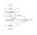
図1は、充放電装置の一実施例を示す図である。図1の充放電装置1は充電率推定装置を有し、電池2、電圧計測部3、制御部4、記憶部5、充電器6、スイッチSW1、SW2などから構成される。図1の負荷7は、充放電装置1からの電力を受電して動作する装置である。動作する装置は、例えば、車両に搭載されるモータなどが考えられる。
Hereinafter, embodiments will be described in detail based on the drawings.
The first embodiment will be described.
FIG. 1 is a diagram illustrating an embodiment of a charge / discharge device. The charging / discharging device 1 in FIG. 1 has a charging rate estimation device, and includes a
なお、充電率推定装置は、電圧計測部3、制御部4、記憶部5、スイッチSW1、SW2などを有する。
電池2は、分極が大きくかつ分極解消に長時間を要し、充放電のヒステリシスが大きい二次電池などである。二次電池として、例えば、負極にSiO負極を利用したリチウムイオン二次電池などが考えられる。ただし、SiOを負極に用いたリチウムイオン二次電池に限定されるものではない。
The charging rate estimation apparatus includes a
The
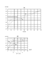
本実施形態における分極が大きくかつ分極解消に長時間を要し、充放電のヒステリシスが大きい二次電池について説明する。図2は、充放電時のSOC−OCV特性の一実施例を示す図である。図2の図201、図202は縦軸に開回路電圧(OCV[V])が示され、横軸に充電率(SOC[%])が示され、温度25℃において通電停止から3時間が経過した状態を示している。充電時のSOC−OCV特性は曲線203に示され、放電時のSOC−OCV特性は曲線204に示されている。
A secondary battery having a large polarization, a long time for depolarization, and a large charge / discharge hysteresis will be described in the present embodiment. FIG. 2 is a diagram illustrating an example of SOC-OCV characteristics during charging and discharging. In FIG. 201 and FIG. 202 of FIG. 2, the vertical axis indicates the open circuit voltage (OCV [V]), the horizontal axis indicates the charging rate (SOC [%]), and the temperature is 25 ° C. The elapsed state is shown. The SOC-OCV characteristic at the time of charging is shown by a
分極が大きい二次電池とは、例えば、負極にカーボン負極を利用した従来の二次電池の分極より大きい二次電池である。
SiO負極を利用した二次電池の場合、図202の例では、充放電時の開回路電圧3.3[V]における点Aと点Bの充電率の差(ヒステリシス)が15.5±7.5[%]である。これは、曲線203上の点Aと曲線204上の点Bは、点Aと点Bの充電率の平均である15.5[%]から充電率が7.5[%]離れていることを示す。また、カーボン負極を利用した二次電池の場合、温度25℃において通電停止から3時間が経過した状態において、充放電時の開回路電圧3.3[V]における充電率の差(ヒステリシス)を測定した結果として4.4±0.2[%]を得ているものとする。この場合に、カーボン負極を利用した二次電池の充電率の差より、SiO負極を用いた二次電池の充電率の差が大きいので、SiO負極を用いた二次電池は分極が大きい二次電池となる。なお、本例では充放電時の開回路電圧3.3[V]で求めた充電率の差を用いて比較をしているが、充放電時の充電率の差が最大になる開回路電圧は3.3[V]に限らない。
The secondary battery having a large polarization is, for example, a secondary battery having a larger polarization than that of a conventional secondary battery using a carbon negative electrode as a negative electrode.
In the case of the secondary battery using the SiO negative electrode, in the example of FIG. 202, the difference (hysteresis) between the charging rates at point A and point B at the open circuit voltage 3.3 [V] during charging and discharging is 15.5 ± 7. .5 [%]. This is because point A on the
分極解消に長時間を要する二次電池とは、例えば、負極にカーボン負極を利用した従来の二次電池の分極を解消する時間より長い分極解消時間を要する二次電池である。カーボン負極を利用した二次電池の充電率が、例えば、分極が10分内に解消する場合、10分以上経過しても分極が解消しない二次電池は、分極解消に長時間を要する二次電池となる。より詳しくは、10分以上経過しても分極が解消せずに、SOC−OCV特性による充電率が±1[%]未満にならない場合、分極解消に長時間を要する二次電池となる。これは、同じ電圧における、充電時の曲線上の点と放電時の曲線上の点が、各点の充電率の平均値から充電率が1[%]以上離れている場合である。 A secondary battery that requires a long time for depolarization is, for example, a secondary battery that requires a longer depolarization time than the time required to depolarize a conventional secondary battery that uses a carbon negative electrode for the negative electrode. When the charge rate of a secondary battery using a carbon anode is, for example, the polarization is resolved within 10 minutes, the secondary battery that does not resolve the polarization even after 10 minutes or more is a secondary battery that requires a long time to depolarize. It becomes a battery. More specifically, when the polarization does not disappear even after 10 minutes or more and the charging rate according to the SOC-OCV characteristic does not become less than ± 1 [%], the secondary battery takes a long time to eliminate the polarization. This is a case where a point on the curve at the time of charging and a point on the curve at the time of discharging at the same voltage are separated from the average value of the charging rate at each point by 1 [%] or more.
なお、図1の例では1つの電池を用いて説明しているが1つの電池に限定されるものではなく、複数の電池を用いてもよい。
電圧計測部3は電池2の電圧を計測する。例えば、電圧計などが考えられる。また、電圧計測部3が計測したデータは制御部4に出力される。
In the example of FIG. 1, the description is made using one battery, but the invention is not limited to one battery, and a plurality of batteries may be used.
The voltage measuring
制御部4(コンピュータなど)は、CPU(Central Processing Unit)、マルチコアCPU、プログラマブルなデバイス(FPGA(Field Programmable Gate Array)、PLD(Programmable Logic Device)など)を用いることが考えられる。 The control unit 4 (computer or the like) may be a CPU (Central Processing Unit), a multi-core CPU, a programmable device (FPGA (Field Programmable Gate Array), PLD (Programmable Logic Device), or the like).
記憶部5は、例えばRead Only Memory(ROM)、Random Access Memory(RAM)などのメモリやハードディスクなどが考えられる。なお、記憶部5にはパラメータ値、変数値などのデータを記憶してもよいし、実行時のワークエリアとして用いてもよい。また、制御部4が記憶部を有している場合には記憶部5を用いなくてもよい。
The
充電器6は、給電装置から電力を受電して電池2に充電するための装置である。
スイッチSW1、SW2は、制御部4からの指示により充電と放電とを切り替えるスイッチで、リレーなどを用いることが考えられる。本例では、2つのスイッチSW1、SW2を用いて充電と放電の切り替えをしているが図1の回路に限定されるものではない。
The
The switches SW1 and SW2 are switches that switch between charging and discharging according to an instruction from the
制御部について説明する。
制御部4は、充電モードの場合に電圧計測部3から測定した電池2の閉回路電圧を用いて、充電モード情報を参照し、充電率を推定する充電推定部8を有する。充電モードは外部から充電器6を介して電池2に充電をしているモードである。充電モード情報は、充電器6が定電流充電をするときの電池2の閉回路電圧と充電率とを関連付けた情報である。
The control unit will be described.
The
また、制御部4は、放電モードの場合に測定した閉回路電圧を用いて、放電モード情報を参照し、充電状態を推定する放電推定部9を有する。放電モードは車両が走行しているモードである。放電モード情報は、決められた動作パターンで車両などを動作させて求められる電池2の放電パターンを用いて生成された閉回路電圧と充電率とを関連付けた情報である。
Moreover, the
なお、充電モード情報および放電モード情報は記憶部5に記憶してもよい。
充電モード情報および放電モード情報の閉回路電圧と充電率の関係について説明をする。
Note that the charging mode information and the discharging mode information may be stored in the
The relationship between the closed circuit voltage of the charging mode information and the discharging mode information and the charging rate will be described.
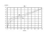
図3は、充放電時のSOC−CCV特性の一実施例を示す図である。図3のSOC−CCV特性を示す図301の曲線302は、充電器6が定電流充電をするときの電池2の閉回路電圧と充電率との関係を示している。充電モードにおける閉回路電圧と充電率との関係は、例えば、実験やシミュレーションにより求める。
FIG. 3 is a diagram illustrating an example of SOC-CCV characteristics during charging and discharging. A
図301の曲線303は、決められた動作パターンで車両などを動作させて求められる電池2の放電パターンを用いて生成された閉回路電圧と充電状態との関係を示している。
決められた動作パターンとは、車両が電気自動車(EV)やプラグインハイブリッド車(PHV)の場合には、走行パターンから測定する燃費測定方法JC−08モード、LA#4モードなどが考えられる。フォークリフトの場合は、予め決められた走行パターンや作業パターンを用いることが考えられる。
A
As the determined operation pattern, when the vehicle is an electric vehicle (EV) or a plug-in hybrid vehicle (PHV), a fuel consumption measurement method JC-08 mode,
放電パターンは、走行パターンや作業パターンで車両を動作させたときの車両に搭載された電池2に代表される放電時の閉回路電圧のパターンである。放電モードにおける閉回路電圧と充電率との関係は、放電時の閉回路電圧を用いて実験やシミュレーションにより求める。
The discharge pattern is a pattern of a closed circuit voltage at the time of discharge typified by the
制御部の動作について説明する。
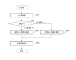
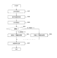
図4は、実施形態1の動作の一実施例を示す図である。ステップS401では、制御部4が閉回路電圧を電圧計測部3から取得する。ステップS402では、制御部4が放電モードであるか充電モードであるか否かを判定し、放電モードである場合(Yes)にはステップS403に移行し、充電モードである場合(No)にはステップS404に移行する。
The operation of the control unit will be described.
FIG. 4 is a diagram illustrating an example of the operation according to the first embodiment. In step S <b> 401, the
ステップS403では、制御部4が放電モード情報を参照し、電圧計測部3から取得した閉回路電圧に対応する充電率を取得する。ステップS404では、制御部4が充電モード情報を参照し、電圧計測部3から取得した閉回路電圧に対応する充電率を取得する。ステップS405では制御部4が充電率を決定する。
In step S <b> 403, the
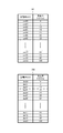
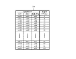
図5は、充電モード情報と放電モード情報のデータ構造の一実施例を示す図である。充電モード情報501は、充電時の閉回路電圧「充電時CCV」と閉回路電圧に対応する充電率「充電率SOC[%]」に記憶される情報を有する。「充電時CCV」には、本例では閉回路電圧を示す情報「cm00」「cm01」「cm02」「cm03」「cm04」「cm05」「cm06」・・・「cm17」「cm18」「cm19」「cm20」が記憶されている。「充電率SOC[%]」には、本例では充電率を示す情報「0」「5」「10」「15」「20」「25」「30」・・・「85」「90」「95」「100」が、閉回路電圧に関連付けられて記憶されている。
FIG. 5 is a diagram illustrating an example of the data structure of the charging mode information and the discharging mode information. The charging
放電モード情報502は、放電時の閉回路電圧「放電時CCV」と閉回路電圧に対応する充電率「充電率SOC[%]」に記憶される情報を有する。「放電時CCV」には、本例では閉回路電圧を示す情報「dm00」「dm01」「dm02」「dm03」「dm04」「dm05」「dm06」・・・「dm17」「dm18」「dm19」「dm20」が記憶されている。「充電率SOC[%]」には、本例では充電率を示す情報「0」「5」「10」「15」「20」「25」「30」・・・「85」「90」「95」「100」が、閉回路電圧に関連付けられて記憶されている。
The
実施形態1によれば、分極が大きくかつ分極解消に長時間を要し、SOC−OCV特性において充放電のヒステリシスが大きい電池の充電率の推定を、充電時と放電時で推定に用いる情報を変えることにより、精度よく推定することができるという効果を奏する。 According to the first embodiment, estimation of the charging rate of a battery having a large polarization and a long time for depolarization and a large charge / discharge hysteresis in the SOC-OCV characteristic is used for estimation during charging and discharging. By changing it, there is an effect that it can be estimated accurately.
実施形態2について説明をする。
実施形態2では充電方法ごとに充電モード情報を用意する。図6は、実施形態2の動作の一実施例を示す図である。ステップS601では、制御部4が閉回路電圧を電圧計測部3から取得する。ステップS602では、制御部4が充電方法情報を取得する。充電方法情報は充電方法を示す情報で、例えば、100V充電、200V充電、急速充電などを示す情報を有する。100V充電をする場合には、100V充電を示す情報を有する充電方法情報を制御部4が取得する。
A second embodiment will be described.
In the second embodiment, charging mode information is prepared for each charging method. FIG. 6 is a diagram illustrating an example of the operation according to the second embodiment. In step S <b> 601, the
ステップS603では、制御部4が放電モードであるか充電モードであるか否かを判定し、放電モードである場合(Yes)にはステップS604に移行し、充電モードである場合(No)にはステップS605に移行する。
In step S603, it is determined whether the
ステップS604では、制御部4が実施形態1で用いる放電モード情報を参照し、電圧計測部3から取得した閉回路電圧に対応する充電率を取得する。ステップS605では、制御部4が実施形態2で用いる充電モード情報701を参照し、電圧計測部3から取得した閉回路電圧に対応する充電率を取得する。ステップS606では制御部4が充電率を決定する。
In step S604, the
図7は、実施形態2の充電モード情報のデータ構造の一実施例を示す図である。充電モード情報701は、充電時の閉回路電圧「充電時CCV」と閉回路電圧に対応する充電率「充電率SOC[%]」に記憶される情報を有する。また、「充電時CCV」は、100Vで充電する際の閉回路電圧を記憶する「100V」、200Vで充電する際の閉回路電圧を記憶する「200V」、急速充電する際の閉回路電圧を記憶する「急速充電」を有する。
FIG. 7 is a diagram illustrating an example of the data structure of the charging mode information according to the second embodiment. The charging
本例では、「100V」には閉回路電圧を示す情報「cm00」「cm01」「cm02」「cm03」「cm04」「cm05」「cm06」・・・「cm17」「cm18」「cm19」「cm20」が記憶されている。「200V」には閉回路電圧を示す情報「cn00」「cn01」「cn02」「cn03」「cn04」「cn05」「cn06」・・・「cn17」「cn18」「cn19」「cn20」が記憶されている。「急速充電」には閉回路電圧を示す情報「cr00」「cr01」「cr02」「cr03」「cr04」「cr05」「cr06」・・・「cr17」「cr18」「cr19」「cr20」が記憶されている。「充電率SOC[%]」には、本例では充電率を示す情報「0」「5」「10」「15」「20」「25」「30」・・・「85」「90」「95」「100」が、「100V」「200V」「急速充電」それぞれに記憶されている閉回路電圧を示す情報に関連付けられて記憶されている。 In this example, “100 V” includes information “cm00”, “cm01”, “cm02”, “cm03”, “cm04”, “cm05”, “cm06”,... “Cm17”, “cm18”, “cm19”, “cm20”. Is stored. Information “cn00”, “cn01” “cn02” “cn03” “cn04” “cn05” “cn06”... “Cn17” “cn18” “cn19” “cn20” indicating the closed circuit voltage is stored in “200 V”. ing. Information “cr00” “cr01” “cr02” “cr03” “cr04” “cr05” “cr06”... “Cr17” “cr18” “cr19” “cr20” indicating the closed circuit voltage is stored in “rapid charge”. Has been. “Charge rate SOC [%]” includes information “0” “5” “10” “15” “20” “25” “30”... “85” “90” “ “95” and “100” are stored in association with information indicating the closed circuit voltages stored in “100 V”, “200 V”, and “rapid charge”, respectively.
実施形態2によれば、分極が大きくかつ分極解消に長時間を要し、SOC−OCV特性において充放電のヒステリシスが大きい電池の充電率の推定を、充電時と放電時で推定に用いる情報を変えることにより、精度よく推定することができるという効果を奏する。 According to the second embodiment, estimation of the charging rate of a battery having a large polarization and a long time for depolarization and a large charge / discharge hysteresis in the SOC-OCV characteristic is used for estimation during charging and discharging. By changing it, there is an effect that it can be estimated accurately.
なお、充電方法により放電時のSOC−OCV特性が異なる二次電池の場合には、充電方法ごとに閉回路電圧を記憶し、記憶した閉回路電圧に充電率を関連付けた放電モード情報を用いてもよい。 In the case of a secondary battery having different SOC-OCV characteristics during discharging depending on the charging method, the closed circuit voltage is stored for each charging method, and the discharge mode information in which the charging rate is associated with the stored closed circuit voltage is used. Also good.
実施形態3について説明をする。
実施形態3では、計測した閉回路電圧のバラツキを補正することで、充電率を推定する精度を向上させる。閉回路電圧をばらつかせる因子として、電流負荷、電池2または電池2の周辺の温度、電池容量、電池2の劣化などが考えられる。
The third embodiment will be described.
In the third embodiment, the accuracy of estimating the charging rate is improved by correcting the variation in the measured closed circuit voltage. Factors that cause the closed circuit voltage to vary include current load, temperature of
図8は、実施形態3の動作の一実施例を示す図である。ステップS801では、制御部4が閉回路電圧を電圧計測部3から取得する。ステップS802では、制御部4が因子情報を取得する。因子情報は電流負荷、電池2または電池2の周辺の温度、電池容量、電池2の劣化などを示す情報を有する。ステップS803では、制御部4が因子情報に含まれる情報各々に対応する補正係数を求め、補正係数を用いて計測した閉回路電圧を補正する。例えば、電流負荷が変わる場合には、記憶部5などに記憶されている電流負荷に対応した補正係数を取得し、計測した閉回路電圧に乗算し、計測した閉回路電圧を補正する。
FIG. 8 is a diagram illustrating an example of the operation of the third embodiment. In step S <b> 801, the
ステップS804では、制御部4が放電モードであるか充電モードであるか否かを判定し、放電モードである場合(Yes)にはステップS805に移行し、充電モードである場合(No)にはステップS806に移行する。
In step S804, it is determined whether the
ステップS805では、制御部4が実施形態1、2で用いた放電モード情報を参照し、補正した閉回路電圧に対応する充電率を取得する。ステップS806では、制御部4が実施形態1で用いた充電モード情報を参照し、補正した閉回路電圧に対応する充電率を取得する。ステップS807では制御部4が充電率を決定する。
In step S805, the
実施形態3によれば、分極が大きくかつ分極解消に長時間を要し、SOC−OCV特性において充放電のヒステリシスが大きい電池の充電率の推定を、充電時と放電時で推定に用いる情報を変えることにより、精度よく推定することができるという効果を奏する。 According to the third embodiment, the information on the estimation of the charging rate of the battery that has a large polarization and requires a long time to depolarize and has a large charge / discharge hysteresis in the SOC-OCV characteristics is used for the estimation at the time of charging and discharging. By changing it, there is an effect that it can be estimated accurately.
なお、充電方法により放電時のSOC−OCV特性が異なる二次電池の場合には、充電方法ごとに閉回路電圧を記憶し、記憶した閉回路電圧に充電率を関連付けた放電モード情報を用いてもよい。 In the case of a secondary battery having different SOC-OCV characteristics during discharging depending on the charging method, the closed circuit voltage is stored for each charging method, and the discharge mode information in which the charging rate is associated with the stored closed circuit voltage is used. Also good.
また、本発明は、上記実施の形態に限定されるものでなく、本発明の要旨を逸脱しない範囲内で種々の改良、変更が可能である。 The present invention is not limited to the above-described embodiment, and various improvements and modifications can be made without departing from the gist of the present invention.
1 充放電装置、
2 電池、
3 電圧計測部、
4 制御部、
5 記憶部、
6 充電器、
7 負荷、
8 充電推定部、
9 放電推定部、
SW1、SW2 スイッチ、
501、701 充電モード情報、
502 放電モード情報
1 Charging / discharging device,
2 batteries,
3 Voltage measurement unit,
4 control unit,
5 storage unit,
6 Charger,
7 load,
8 Charge estimation unit,
9 Discharge estimation unit,
SW1, SW2 switch,
501, 701 charging mode information,
502 Discharge mode information
Claims (4)
充電モードの場合、充電器が定電流充電をするときの前記電池の閉回路電圧と0〜100%の充電率とが関連付けられた複数の充電モード情報の中から充電方法を有する充電方法情報を用いて前記充電方法情報に対応する充電モード情報を参照し、参照した前記充電モード情報から測定した前記閉回路電圧のみを用いて充電率を取得し、取得した前記充電率を前記電池の充電率とする充電推定部と、
放電モードの場合、決められた動作パターンで車両を動作させて求められる前記電池の放電パターンを用いて生成された閉回路電圧と充電率とが関連付けられた放電モード情報を参照し、参照した前記放電モード情報から測定した前記閉回路電圧のみを用いて充電率を取得し、取得した前記充電率を前記電池の充電率とする放電推定部と、
を備えることを特徴とする充電率推定装置。 A voltage measuring unit for measuring the closed circuit voltage of the battery using the SiO negative electrode;
If the charging mode, the charging process information having a charging method from the plurality of charging mode information closed circuit voltage and 0 to 100% of charging rate and is associated with the battery when the charger is a constant current charge charging rate of the charging mode information referring to the, referenced using only the closed circuit voltage measured from said charge mode information acquires the charging rate, the batteries obtained the charging rate corresponding to the charging method information using A charge estimation unit, and
If the discharge mode, referring to the discharge mode information and the generated closed circuit voltage and the charging rate is associated with the discharge pattern of the battery obtained by operating the vehicle in determined Me was operating pattern, and reference a discharge estimation unit said measured from the discharge mode information using a closed circuit voltage only obtains the charging rate and the acquired the charging rate and the charging rate of the battery,
A charging rate estimation device comprising:
SiO負極を利用した電池の閉回路電圧を取得し、
充電モードの場合、充電器が定電流充電をするときの前記電池の閉回路電圧と0〜100%の充電率とが関連付けられた複数の充電モード情報の中から充電方法を有する充電方法情報を用いて前記充電方法情報に対応する充電モード情報を参照し、参照した前記充電モード情報から測定した前記閉回路電圧のみを用いて充電率を取得し、取得した前記充電率を前記電池の充電率とする処理、
放電モードの場合、決められた動作パターンで車両を動作させて求められる前記電池の放電パターンを用いて生成された閉回路電圧と充電率とが関連付けられた放電モード情報を参照し、参照した前記放電モード情報から測定した前記閉回路電圧のみを用いて充電率を取得し、取得した前記充電率を前記電池の充電率とする処理、
を実行することを特徴とする充電率推定方法。 Computer
Obtain the closed circuit voltage of the battery using the SiO negative electrode,
If the charging mode, the charging process information having a charging method from the plurality of charging mode information closed circuit voltage and 0 to 100% of charging rate and is associated with the battery when the charger is a constant current charge charging rate of the charging mode information referring to the, referenced using only the closed circuit voltage measured from said charge mode information acquires the charging rate, the batteries obtained the charging rate corresponding to the charging method information using Processing,
If the discharge mode, referring to the discharge mode information and the generated closed circuit voltage and the charging rate is associated with the discharge pattern of the battery obtained by operating the vehicle in determined Me was operating pattern, and reference processing said measured from the discharge mode information using a closed circuit voltage only obtains the charging rate and the acquired the charging rate and the charging rate of the battery,
The charging rate estimation method characterized by performing.
Priority Applications (6)
| Application Number | Priority Date | Filing Date | Title |
|---|---|---|---|
| JP2013008171A JP6221237B2 (en) | 2013-01-21 | 2013-01-21 | CHARGE RATE ESTIMATION DEVICE AND CHARGE RATE ESTIMATION METHOD |
| CN201380070403.7A CN104937431A (en) | 2013-01-21 | 2013-10-25 | Charge rate estimation device and charge rate estimation method |
| US14/760,830 US10466303B2 (en) | 2013-01-21 | 2013-10-25 | State-of-charge estimation device and state-of-charge estimation method |
| DE112013006471.5T DE112013006471T5 (en) | 2013-01-21 | 2013-10-25 | State of charge estimator and state of charge estimation method |
| PCT/JP2013/079025 WO2014112175A1 (en) | 2013-01-21 | 2013-10-25 | Charge rate estimation device and charge rate estimation method |
| JP2017171672A JP6380635B2 (en) | 2013-01-21 | 2017-09-07 | CHARGE RATE ESTIMATION DEVICE AND CHARGE RATE ESTIMATION METHOD |
Applications Claiming Priority (1)
| Application Number | Priority Date | Filing Date | Title |
|---|---|---|---|
| JP2013008171A JP6221237B2 (en) | 2013-01-21 | 2013-01-21 | CHARGE RATE ESTIMATION DEVICE AND CHARGE RATE ESTIMATION METHOD |
Related Child Applications (1)
| Application Number | Title | Priority Date | Filing Date |
|---|---|---|---|
| JP2017171672A Division JP6380635B2 (en) | 2013-01-21 | 2017-09-07 | CHARGE RATE ESTIMATION DEVICE AND CHARGE RATE ESTIMATION METHOD |
Publications (2)
| Publication Number | Publication Date |
|---|---|
| JP2014139521A JP2014139521A (en) | 2014-07-31 |
| JP6221237B2 true JP6221237B2 (en) | 2017-11-01 |
Family
ID=51209287
Family Applications (2)
| Application Number | Title | Priority Date | Filing Date |
|---|---|---|---|
| JP2013008171A Expired - Fee Related JP6221237B2 (en) | 2013-01-21 | 2013-01-21 | CHARGE RATE ESTIMATION DEVICE AND CHARGE RATE ESTIMATION METHOD |
| JP2017171672A Expired - Fee Related JP6380635B2 (en) | 2013-01-21 | 2017-09-07 | CHARGE RATE ESTIMATION DEVICE AND CHARGE RATE ESTIMATION METHOD |
Family Applications After (1)
| Application Number | Title | Priority Date | Filing Date |
|---|---|---|---|
| JP2017171672A Expired - Fee Related JP6380635B2 (en) | 2013-01-21 | 2017-09-07 | CHARGE RATE ESTIMATION DEVICE AND CHARGE RATE ESTIMATION METHOD |
Country Status (5)
| Country | Link |
|---|---|
| US (1) | US10466303B2 (en) |
| JP (2) | JP6221237B2 (en) |
| CN (1) | CN104937431A (en) |
| DE (1) | DE112013006471T5 (en) |
| WO (1) | WO2014112175A1 (en) |
Families Citing this family (32)
| Publication number | Priority date | Publication date | Assignee | Title |
|---|---|---|---|---|
| JP6107562B2 (en) * | 2013-09-19 | 2017-04-05 | 株式会社豊田自動織機 | Battery control unit system |
| JP6558108B2 (en) * | 2015-07-09 | 2019-08-14 | 株式会社豊田自動織機 | Power storage device and power storage method |
| US11031799B2 (en) * | 2015-12-01 | 2021-06-08 | Sony Corporation | Power supply management integrated circuit, electronic device, and control method of power supply management integrated circuit |
| JP6830318B2 (en) * | 2016-01-15 | 2021-02-17 | 株式会社Gsユアサ | Power storage element management device, power storage element module, vehicle and power storage element management method |
| CN109791183B (en) * | 2016-10-06 | 2021-09-03 | 株式会社丰田自动织机 | Electricity storage device |
| KR102634814B1 (en) | 2016-11-16 | 2024-02-07 | 삼성전자주식회사 | Method and apparatus for estimating battery state |
| US20200018798A1 (en) * | 2017-03-29 | 2020-01-16 | Gs Yuasa International Ltd. | Storage amount estimation device, energy storage module, storage amount estimation method, and computer program |
| JP6406468B1 (en) | 2017-03-29 | 2018-10-17 | 株式会社Gsユアサ | Storage amount estimation device, storage module, storage amount estimation method, and computer program |
| JP6822300B2 (en) | 2017-04-27 | 2021-01-27 | トヨタ自動車株式会社 | Charge rate estimation method and in-vehicle battery system |
| JP6834757B2 (en) | 2017-04-28 | 2021-02-24 | トヨタ自動車株式会社 | Battery system |
| JP6406470B1 (en) * | 2017-06-02 | 2018-10-17 | 株式会社Gsユアサ | Management device, power storage module, management method, and computer program |
| JP6863258B2 (en) | 2017-12-12 | 2021-04-21 | トヨタ自動車株式会社 | Stress estimation method for secondary battery system and active material of secondary battery |
| JP6927009B2 (en) | 2017-12-12 | 2021-08-25 | トヨタ自動車株式会社 | Secondary battery system and SOC estimation method for secondary batteries |
| JP6927008B2 (en) | 2017-12-12 | 2021-08-25 | トヨタ自動車株式会社 | Secondary battery system and SOC estimation method for secondary batteries |
| KR102458526B1 (en) * | 2018-02-07 | 2022-10-25 | 주식회사 엘지에너지솔루션 | Apparatus and method for estimating soc base on operating state of battery |
| JP2020038146A (en) | 2018-09-05 | 2020-03-12 | トヨタ自動車株式会社 | Secondary battery system and soc estimation method for secondary battery |
| CN110911764B (en) | 2018-09-14 | 2023-01-10 | 丰田自动车株式会社 | Secondary battery system and method for estimating deterioration state of secondary battery |
| JP2020046420A (en) * | 2018-09-14 | 2020-03-26 | トヨタ自動車株式会社 | Secondary battery system and secondary battery deterioration state estimation method |
| JP7115439B2 (en) * | 2018-09-14 | 2022-08-09 | トヨタ自動車株式会社 | SECONDARY BATTERY SYSTEM AND SECONDARY BATTERY INTERNAL STATE ESTIMATION METHOD |
| EP3624252A1 (en) | 2018-09-14 | 2020-03-18 | Toyota Jidosha Kabushiki Kaisha | Secondary battery system and method of estimating an internal state of secondary battery |
| JP7128709B2 (en) | 2018-10-04 | 2022-08-31 | 日本たばこ産業株式会社 | Suction component generator |
| JP6545880B1 (en) * | 2018-10-11 | 2019-07-17 | 日本たばこ産業株式会社 | Suction component generation device, control circuit, control method and control program for suction component generation device |
| US11133534B2 (en) | 2019-02-22 | 2021-09-28 | Aurora Flight Sciences Corporation | Programmable battery pack |
| JP6630866B1 (en) * | 2019-06-19 | 2020-01-15 | 日本たばこ産業株式会社 | Suction component generation device, control circuit, control method of suction component generation device, and control program |
| JP6630867B1 (en) * | 2019-06-19 | 2020-01-15 | 日本たばこ産業株式会社 | Suction component generation device, control circuit, control method of suction component generation device, and control program |
| JP7342671B2 (en) * | 2019-06-20 | 2023-09-12 | 株式会社Gsユアサ | Development support device, development support method, and state detection method |
| CN112379293B (en) * | 2019-06-24 | 2022-09-23 | 宁德时代新能源科技股份有限公司 | Charge state correction method and device |
| KR102780292B1 (en) * | 2019-12-11 | 2025-03-11 | 주식회사 엘지에너지솔루션 | Battery management system, battery management method, battery pack, and electric vehicle |
| JP7089547B2 (en) * | 2020-04-30 | 2022-06-22 | プライムアースEvエナジー株式会社 | Secondary battery status determination method and status determination device |
| CN115113069B (en) * | 2021-12-24 | 2024-12-27 | 长城汽车股份有限公司 | Battery SOC estimation method and related device |
| CN115113061B (en) * | 2021-12-24 | 2024-11-22 | 长城汽车股份有限公司 | Method and related device for correcting battery SOC |
| KR20240101261A (en) * | 2022-12-23 | 2024-07-02 | 주식회사 엘지에너지솔루션 | Apparatus and method for managing battery |
Family Cites Families (30)
| Publication number | Priority date | Publication date | Assignee | Title |
|---|---|---|---|---|
| JPH07198808A (en) | 1993-12-28 | 1995-08-01 | Honda Motor Co Ltd | Battery remaining capacity display for electric vehicles |
| JP3169867B2 (en) * | 1997-11-14 | 2001-05-28 | 北海道日本電気ソフトウェア株式会社 | Battery level detection method and device |
| JP4088993B2 (en) * | 1998-02-13 | 2008-05-21 | 株式会社ジーエス・ユアサコーポレーション | Non-aqueous electrolyte secondary battery discharge control method |
| GB9804684D0 (en) | 1998-03-05 | 1998-04-29 | Lucas Ind Plc | Method and apparatus for estimating the charge in a battery |
| US6232744B1 (en) * | 1999-02-24 | 2001-05-15 | Denso Corporation | Method of controlling battery condition of self-generation electric vehicle |
| JP2001281306A (en) | 2000-03-28 | 2001-10-10 | Mitsubishi Electric Corp | Rechargeable battery remaining capacity detection device |
| US6359419B1 (en) | 2000-12-27 | 2002-03-19 | General Motors Corporation | Quasi-adaptive method for determining a battery's state of charge |
| JP4292721B2 (en) * | 2001-02-14 | 2009-07-08 | 株式会社日本自動車部品総合研究所 | Battery state control method for hybrid vehicle |
| JP2004301783A (en) * | 2003-03-31 | 2004-10-28 | Yazaki Corp | Battery condition monitoring method and device |
| KR100494947B1 (en) * | 2003-08-07 | 2005-06-13 | 현대자동차주식회사 | A method for calculating a steady state battery terminal voltage |
| US7570024B2 (en) * | 2004-04-06 | 2009-08-04 | Cobasys, Llc | Battery state of charge voltage hysteresis estimator |
| US8427109B2 (en) * | 2004-04-06 | 2013-04-23 | Chevron Technology Ventures Llc | Battery state of charge reset |
| US7554295B2 (en) * | 2004-04-06 | 2009-06-30 | Cobasys, Llc | Determination of IR-free voltage in hybrid vehicle applications |
| US20080135801A1 (en) * | 2004-07-29 | 2008-06-12 | Shingo Kizaki | Silicon Monoxide Powder For Secondary Battery and Method For Producing the Same |
| JP4275078B2 (en) | 2005-01-13 | 2009-06-10 | 三洋電機株式会社 | Battery current limit control method |
| DE102005026597A1 (en) | 2005-06-09 | 2006-12-21 | Daimlerchrysler Ag | Rechargeable battery charge state determination method for vehicle, entails carrying out mathematical inversion of Preisach model after defining off-load voltage of battery, and from this calculating actual charge state of battery |
| JP5273794B2 (en) * | 2006-08-29 | 2013-08-28 | 日本電気株式会社 | Method and apparatus for estimating SOC value of secondary battery, and degradation determination method and apparatus |
| JP2010019595A (en) * | 2008-07-08 | 2010-01-28 | Fuji Heavy Ind Ltd | Residual capacity calculating apparatus of storage device |
| WO2010042898A1 (en) * | 2008-10-10 | 2010-04-15 | Deeya Energy Technologies, Inc. | Method and apparatus for determining state of charge of a battery |
| WO2010064392A1 (en) * | 2008-12-05 | 2010-06-10 | パナソニック株式会社 | Battery pack |
| EP2457107A4 (en) * | 2009-07-23 | 2014-07-02 | Texas Instruments Inc | Systems and methods for determining battery state of charge |
| JP5493657B2 (en) * | 2009-09-30 | 2014-05-14 | 新神戸電機株式会社 | Storage battery device and battery state evaluation device and method for storage battery |
| JP5287844B2 (en) * | 2010-12-27 | 2013-09-11 | 株式会社デンソー | Secondary battery remaining capacity calculation device |
| CN102540081B (en) * | 2010-12-29 | 2015-01-21 | 上海汽车集团股份有限公司 | Method for determining charge state of vehicle-mounted storage battery |
| JP2012210128A (en) * | 2011-03-30 | 2012-10-25 | Equos Research Co Ltd | Electric vehicle charging system |
| JP5683372B2 (en) * | 2011-04-27 | 2015-03-11 | デクセリアルズ株式会社 | Charge / discharge control device, battery pack, electric device, and charge / discharge control method |
| JP5719236B2 (en) * | 2011-05-31 | 2015-05-13 | プライムアースEvエナジー株式会社 | Secondary battery control device |
| KR101863036B1 (en) * | 2011-11-30 | 2018-06-01 | 주식회사 실리콘웍스 | Method for estimating the state of charge of battery and battery management system |
| CN102636759A (en) * | 2012-05-02 | 2012-08-15 | 上海樟村电子有限公司 | Method for accurately calculating battery electric quantity system-on-chip (SOC) in real time |
| CN102662148B (en) * | 2012-05-09 | 2014-06-18 | 中国农业大学 | On-line feedback battery state of charge (SOC) predicting method |
-
2013
- 2013-01-21 JP JP2013008171A patent/JP6221237B2/en not_active Expired - Fee Related
- 2013-10-25 WO PCT/JP2013/079025 patent/WO2014112175A1/en not_active Ceased
- 2013-10-25 DE DE112013006471.5T patent/DE112013006471T5/en not_active Withdrawn
- 2013-10-25 US US14/760,830 patent/US10466303B2/en not_active Expired - Fee Related
- 2013-10-25 CN CN201380070403.7A patent/CN104937431A/en active Pending
-
2017
- 2017-09-07 JP JP2017171672A patent/JP6380635B2/en not_active Expired - Fee Related
Also Published As
| Publication number | Publication date |
|---|---|
| US20150355285A1 (en) | 2015-12-10 |
| DE112013006471T5 (en) | 2015-10-01 |
| CN104937431A (en) | 2015-09-23 |
| JP6380635B2 (en) | 2018-08-29 |
| JP2014139521A (en) | 2014-07-31 |
| US10466303B2 (en) | 2019-11-05 |
| JP2017227653A (en) | 2017-12-28 |
| WO2014112175A1 (en) | 2014-07-24 |
Similar Documents
| Publication | Publication Date | Title |
|---|---|---|
| JP6380635B2 (en) | CHARGE RATE ESTIMATION DEVICE AND CHARGE RATE ESTIMATION METHOD | |
| JP5929778B2 (en) | CHARGE RATE ESTIMATION DEVICE AND CHARGE RATE ESTIMATION METHOD | |
| JP5109304B2 (en) | Battery remaining capacity detection device | |
| JP6500789B2 (en) | Control system of secondary battery | |
| JP2023538052A (en) | Battery management system, battery pack, electric vehicle and battery management method | |
| CN110549909A (en) | SOH calculation method, device and electric vehicle of power battery pack | |
| CN112384814A (en) | Secondary battery parameter estimation device, secondary battery parameter estimation method, and program | |
| WO2012137456A1 (en) | Method for determining remaining lifetime | |
| JP4816097B2 (en) | Battery SOC calculation device | |
| JP7167581B2 (en) | Secondary battery device | |
| JP2018151175A (en) | Estimation device, estimation method, and estimation program | |
| JP6822358B2 (en) | Rechargeable battery system | |
| JP6866756B2 (en) | Charge rate estimator | |
| JP2020079764A (en) | Secondary battery status determination method | |
| JP2020517076A (en) | Battery resistance estimating apparatus and method | |
| JP2018050373A (en) | Battery system | |
| JP6115446B2 (en) | Full charge capacity calculation device | |
| WO2013057784A1 (en) | Battery control device and secondary battery system | |
| JP6848775B2 (en) | Lithium ion secondary battery system | |
| JP7295658B2 (en) | state estimator | |
| JP6747333B2 (en) | Secondary battery system | |
| JP2019184316A (en) | Device and method for estimation | |
| US20220385078A1 (en) | Charging control device, vehicle, charging control method, and storage medium storing control program | |
| JP2014176158A (en) | Voltage equalization device and voltage equalization method | |
| JP6805875B2 (en) | Battery open circuit voltage estimation device |
Legal Events
| Date | Code | Title | Description |
|---|---|---|---|
| A621 | Written request for application examination |
Free format text: JAPANESE INTERMEDIATE CODE: A621 Effective date: 20150604 |
|
| A131 | Notification of reasons for refusal |
Free format text: JAPANESE INTERMEDIATE CODE: A131 Effective date: 20160315 |
|
| A521 | Request for written amendment filed |
Free format text: JAPANESE INTERMEDIATE CODE: A523 Effective date: 20160509 |
|
| A131 | Notification of reasons for refusal |
Free format text: JAPANESE INTERMEDIATE CODE: A131 Effective date: 20160913 |
|
| RD12 | Notification of acceptance of power of sub attorney |
Free format text: JAPANESE INTERMEDIATE CODE: A7432 Effective date: 20161031 |
|
| A521 | Request for written amendment filed |
Free format text: JAPANESE INTERMEDIATE CODE: A523 Effective date: 20161109 |
|
| A521 | Request for written amendment filed |
Free format text: JAPANESE INTERMEDIATE CODE: A821 Effective date: 20161031 |
|
| A131 | Notification of reasons for refusal |
Free format text: JAPANESE INTERMEDIATE CODE: A131 Effective date: 20170321 |
|
| A521 | Request for written amendment filed |
Free format text: JAPANESE INTERMEDIATE CODE: A523 Effective date: 20170331 |
|
| TRDD | Decision of grant or rejection written | ||
| A01 | Written decision to grant a patent or to grant a registration (utility model) |
Free format text: JAPANESE INTERMEDIATE CODE: A01 Effective date: 20170905 |
|
| A61 | First payment of annual fees (during grant procedure) |
Free format text: JAPANESE INTERMEDIATE CODE: A61 Effective date: 20170918 |
|
| R151 | Written notification of patent or utility model registration |
Ref document number: 6221237 Country of ref document: JP Free format text: JAPANESE INTERMEDIATE CODE: R151 |
|
| LAPS | Cancellation because of no payment of annual fees |