US20030197432A1 - Linear motor - Google Patents
Linear motor Download PDFInfo
- Publication number
- US20030197432A1 US20030197432A1 US10/410,135 US41013503A US2003197432A1 US 20030197432 A1 US20030197432 A1 US 20030197432A1 US 41013503 A US41013503 A US 41013503A US 2003197432 A1 US2003197432 A1 US 2003197432A1
- Authority
- US
- United States
- Prior art keywords
- magnetic teeth
- stator
- magnetic
- yoke
- linear motor
- Prior art date
- Legal status (The legal status is an assumption and is not a legal conclusion. Google has not performed a legal analysis and makes no representation as to the accuracy of the status listed.)
- Granted
Links
Images


Classifications
-
- H—ELECTRICITY
- H02—GENERATION; CONVERSION OR DISTRIBUTION OF ELECTRIC POWER
- H02K—DYNAMO-ELECTRIC MACHINES
- H02K41/00—Propulsion systems in which a rigid body is moved along a path due to dynamo-electric interaction between the body and a magnetic field travelling along the path
- H02K41/02—Linear motors; Sectional motors
- H02K41/03—Synchronous motors; Motors moving step by step; Reluctance motors
-
- H—ELECTRICITY
- H02—GENERATION; CONVERSION OR DISTRIBUTION OF ELECTRIC POWER
- H02K—DYNAMO-ELECTRIC MACHINES
- H02K1/00—Details of the magnetic circuit
- H02K1/06—Details of the magnetic circuit characterised by the shape, form or construction
- H02K1/12—Stationary parts of the magnetic circuit
- H02K1/18—Means for mounting or fastening magnetic stationary parts on to, or to, the stator structures
Definitions
- the present invention relates to a linear motor. More particularly, the invention pertains to a linear motor used in a table feed mechanism of a machine tool.
- FIG. 20 is a cross-sectional diagram showing the construction of a conventional linear motor disclosed in Japanese Laid-open Patent Publication No. 2000-217334.
- a stator 1 includes a plurality of permanent magnets 3 a , 3 b arranged in a line at regular intervals on a stator yoke 2 in alternately reversed directions to produce alternating polarities.
- a moving part 4 moves along the stator 1 as if sliding over the stator 1 with a specific distance (gap) therefrom.
- the moving part 4 includes a moving yoke 5 , connecting parts 7 each having a trapezoidal cross section which are held at specific intervals on one side of the moving yoke 5 facing the stator 1 by bolts 6 fitted in the moving yoke 5 , a plurality of magnetic teeth (poles) 8 generally T-shaped in cross section and joined to the individual connecting parts 7 which are fitted into dovetail grooves 8 a formed in a central part of each tooth end, each magnetic tooth 8 having a recess 8 b and a protrusion 8 c formed on opposite sides, and a plurality of magnetic teeth (poles) 9 generally I-shaped in cross section and fitted between the successive magnetic teeth 8 as a recess 9 a and a protrusion 9 b formed on opposite sides of each magnetic tooth 9 fit over and into the protrusion 8 c and the recess 8 b of the adjoining magnetic teeth 8 , respectively. Also included in the moving part 4 are coils 10 individually wound around the magnetic teeth 8 , 9 and a
- the moving part 4 is assembled by first winding the coils 10 around the individual magnetic teeth 8 , 9 .
- the dovetail grooves 8 a formed in the individual magnetic teeth 8 are fitted over the respective connecting parts 7 held by the bolts 6 fitted in the moving yoke 5 by sliding the magnetic teeth 8 in a direction perpendicular to the plane of the paper (FIG. 20) and, when the magnetic teeth 8 have been set into position, they are fixed to the moving yoke 5 by tightening the bolts 6 .
- the individual magnetic teeth 9 are slid between the successive magnetic teeth 8 with the recess 9 a and the protrusion 9 b formed on each magnetic tooth 9 meshed with the protrusion 8 c and the recess 8 b of the adjoining magnetic teeth 8 , respectively.
- the alternately arranged magnetic teeth 8 , 9 and the coils 10 are joined together into a single structure by the resin molding 11 .
- the conventional linear motor is assembled by inserting the magnetic teeth 9 between the successive magnetic teeth 8 as stated above, the coils 10 wound around the magnetic teeth 9 slide over the coils 10 wound around the magnetic teeth 8 with friction. This assembly process could cause damages to the coils 10 , such as an insulation failure or a wire breakage, resulting in a reduction in reliability.
- the conventional linear motor is associated with a poor labor efficiency problem. This is because its assembly involves rather complicated procedures including fitting and sliding the dovetail grooves 8 a formed in the individual magnetic teeth 8 over the respective connecting parts 7 , tightening the bolts 6 to fix the magnetic teeth 8 to the moving yoke 5 , mating the recess 9 a and the protrusion 9 b formed on each magnetic tooth 9 with the protrusion 8 c and the recess 8 b of the adjoining magnetic teeth 8 and sliding them to fit the magnetic teeth 9 between the successive magnetic teeth 8 .
- the stacking thickness of the electromagnetic steel sheets should be increased if it is necessary to increase the width of the individual magnetic teeth due to an increase in motor capacity.
- An increase in the stacking thickness tends to cause an inclination of the stacked electromagnetic steel sheets due to stacking errors as well as a deterioration in assembling efficiency.
- a linear motor comprises a stator including a stator yoke extending in a motor running direction and a plurality of permanent magnets arranged on the stator yoke at regular intervals along the motor running direction in alternately reversed directions to produce alternating polarities, and a moving part positioned generally parallel to the permanent magnets of the stator and separated therefrom by a specific gap, the moving part including a plurality of magnetic teeth arranged side by side along the motor running direction and coils wound around the individual magnetic teeth.
- each of the magnetic teeth has a yoke portion located opposite to a side facing the stator, the yoke portion of each magnetic tooth being held in contact with the yoke portion of each adjoining magnetic tooth, and a tooth portion around which the coil is wound, the tooth portion extending from the yoke portion toward the stator.
- Cutouts formed in end surfaces of the yoke portions of the individual magnetic teeth opposite to their side facing the stator line up to form a groove-shaped channel running through the yoke portions of the successive magnetic teeth, and the multiple magnetic teeth are joined together into a single structure by fitting a connecting member in the groove-shaped channel.
- the linear motor thus constructed offers enhanced reliability and greater assembling efficiency.
- FIGS. 1 A- 1 B are diagrams showing the construction of a linear motor according to a first embodiment of the invention, in which FIG. 1A is a plan view and FIG. 1B is a cross-sectional side view;
- FIG. 2 is a front view of the linear motor of FIGS. 1 A- 1 B;
- FIG. 3 is a plan view showing how magnetic teeth of the linear motor are successively arranged
- FIG. 4 is a front view showing how the magnetic teeth are joined into a single structure by means of connecting bars
- FIG. 5 is a front view showing how the connecting bars are welded to the magnetic teeth
- FIG. 6 is a plan view showing an assembly of the magnetic teeth upon completion of a welding process shown in FIG. 5;
- FIG. 7 is a diagram showing details of how each connecting bar is welded to the magnetic teeth
- FIG. 8 is a plan view showing the construction of a linear motor according to a second embodiment of the invention.
- FIG. 9 is a front view of the linear motor of FIG. 8;
- FIG. 10 is a perspective view showing a process of winding a coil around one of magnetic teeth shown in FIG. 8;
- FIG. 11 is a plan view showing the construction of a linear motor according to a third embodiment of the invention.
- FIG. 12 is a side view of the linear motor of FIG. 11;
- FIG. 13 is a front view of the linear motor of FIG. 11;
- FIGS. 14 A- 14 B are front views showing how connecting bars are welded to individual magnetic teeth shown in FIG. 11 ;
- FIG. 15 is a plan view showing an assembly of the magnetic teeth upon completion of a welding process shown in FIG. 14.
- FIG. 16 is a plan view showing the construction of a linear motor according to a fourth embodiment of the invention.
- FIG. 17 is a front view showing the construction of a linear motor according to a fifth embodiment of the invention.
- FIG. 18 is a diagram showing the relationship between the dimensions of connecting bars and groove-shaped channels
- FIG. 19 is a front view showing how the connecting bars are welded to magnetic teeth.
- FIG. 20 is a cross-sectional diagram showing the construction of a conventional linear motor.
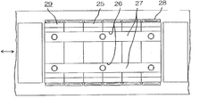
- FIGS. 1 A- 1 B are diagrams showing the construction of a linear motor according to a first embodiment of the invention, in which FIG. 1A is a plan view and FIG. 1B is a cross-sectional side view.
- FIG. 2 is a front view of the linear motor of FIGS. 1 A- 1 B
- FIG. 3 is a plan view showing how magnetic teeth 25 of the linear motor are successively arranged
- FIG. 4 is a front view showing how the magnetic teeth 25 are joined into a single structure by means of connecting bars 27
- FIG. 5 is a front view showing how the connecting bars 27 are welded to the magnetic teeth 25
- FIG. 6 is a plan view showing an assembly of the magnetic teeth 25 upon completion of a welding process shown in FIG. 5
- FIG. 7 is a diagram showing details of how each connecting bar 27 is welded to the magnetic teeth 25 .
- a stator 21 includes a platelike stator yoke 22 extending in a motor running direction shown by double arrows (FIGS. 1 A- 1 B) and a plurality of permanent magnets 23 , 24 arranged on the stator yoke 22 at regular intervals along the motor running direction in alternately reversed directions to produce alternating polarities.
- a moving part 29 Separated by a specific distance from the permanent magnets 23 , 24 arranged on the stator yoke 22 , includes the aforementioned multiple magnetic teeth 25 arranged along the motor running direction, coils 28 individually wound around the magnetic teeth 25 and the aforementioned connecting bars 27 joining together the magnetic teeth 25 into a single structure.
- upper parts of the individual magnetic teeth 25 (that are opposite to ends of the magnetic teeth 25 facing the stator 21 ) constitute yoke portions 25 c , from which tooth portions 25 d extend downward toward the stator 21 .
- the coils 28 are wound around the individual tooth portions 25 d and the multiple magnetic teeth 25 are arranged side by side with side faces of their yoke portions 25 c held in contact with one another.
- a pair of cutouts 25 a (width W1, depth H2) having a rectangular cross section are formed at specific locations in an upper end surface of the yoke portion 25 c of each magnetic tooth 25 in such a manner that the cutouts 25 a in the successive yoke portions 25 c line up along the motor running direction (which is perpendicular to the plane of the paper in FIG. 2).
- cutouts 25 b each having a width equal to one half the width W1 of each cutout 25 a (i.e., W1/2).
- the cutouts 25 a formed in the individual yoke portions 25 c line up in double straight lines and together form a pair of groove-shaped channels 26 running through the successive magnetic teeth 25 (refer to FIGS. 1 A- 1 B).
- the aforementioned connecting bars 27 are fitted in the individual groove-shaped channels 26 all the way along their length to join together the magnetic teeth 25 .
- the coils 28 are wound around the individual magnetic teeth 25 .
- the individual magnetic teeth 25 are then aligned with the side faces of the yoke portions 25 c placed in contact with one another as shown in FIG. 3.
- the cutouts 25 a in the individual yoke portions 25 c line up in double straight lines, together forming the two groove-shaped channels 26 .
- the connecting bars 27 are fitted in the groove-shaped channels 26 as shown in FIG. 4 and welded as shown in FIG. 5, so that the connecting bars 27 are firmly fixed to the yoke portions 25 c of the individual magnetic teeth 25 as shown in FIG. 6.
- the magnetic teeth 25 are joined together by the connecting bars 27 into a single structure, whereby assembly of the moving part 29 is completed.
- the depth H2 of the groove-shaped channels 26 be made slightly smaller than half the height H1 of the connecting bars 27 (i.e., H1/2) so that the welding points P are located generally at the middle of the height H1 of the connecting bars 27 .
- the cutouts 25 a formed in the upper end surfaces of the yoke portions 25 c of the individual magnetic teeth 25 line up in double straight lines, together forming the two groove-shaped channels 26 , and the connecting bars 27 are fitted into these groove-shaped channels 26 to join together the magnetic teeth 25 into a single structure in the aforementioned first embodiment.
- This structure of the embodiment facilitates assembly of the moving part 29 and helps improve assembling efficiency.
- the individual magnetic teeth 25 can be assembled without causing the adjacent coils 28 to slide over each other with friction, and this serves to prevent insulation failures and wire breakage and improve reliability.
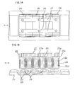
- FIG. 8 is a plan view showing the construction of a linear motor according to a second embodiment of the invention
- FIG. 9 is a front view of the linear motor of FIG. 8
- FIG. 10 is a perspective view showing a process of winding a coil 33 around one of magnetic teeth 25 shown in FIG. 8.
- elements identical to those of the foregoing first embodiment are designated by the same reference numerals and a description of such elements is omitted.
- a stator 31 includes a stator yoke 22 and permanent magnets 23 and 24 alternately arranged in a double row on the stator yoke 22 .
- Each of the magnetic teeth 25 constituting a moving part 37 is formed of a pair of magnetic tooth elements 32 aligned in a direction perpendicular to a motor running direction.
- each pair of magnetic tooth elements 32 is held by a wire-winding jig 34 and turned in a direction shown by an arrow, whereby the two magnetic tooth elements 32 are securely joined together by the coil 33 form by a magnet wire 35 wound around them.
- a plurality of magnetic teeth 25 individually would by the coils 33 as described above are arranged side by side with side faces of their yoke portions 25 c held in contact with one another in the same manner as in the first embodiment.
- cutouts 25 a formed in the individual magnetic teeth 25 line up and together form four parallel groove-shaped channels 26 in a top surface of the moving part 37
- cutouts 25 b formed at both upper corners of the individual magnetic tooth elements 32 also line up and together form a groove-shaped channel 36 bridging the inside upper corners of the double rows of the magnetic tooth elements 32 .
- Three connecting bars 27 are then fitted in the individual groove-shaped channels 26 , 36 as shown in FIG. 9 and fixed therein by welding them at specific points as shown in FIG. 8. Consequently, the individual magnetic teeth 25 are securely joined together by the connecting bars 27 into a single structure, whereby assembly of the moving part 37 is completed.
- each magnetic tooth 25 is formed by winding the coil 33 around a pair of magnetic tooth elements 32 arranged in tandem in a direction perpendicular to the motor running direction in the aforementioned second embodiment.
- This structure of the embodiment makes it possible to flexibly increase (or decrease) in accordance with changes in required power of the linear motor (motor capacity) by a combination of the magnetic tooth elements 32 .
- the embodiment not only serves to improve assembling efficiency but enables the use of the same components for different purposes, facilitates the control of inventory of various components and helps achieve an eventual cost reduction.
- the magnetic teeth are formed by stacking electromagnetic steel sheets, they can be produced by combining the magnetic tooth elements 32 having a standardized shape and dimensions. Consequently, even when the required motor capacity increases, the stacking thickness of the electromagnetic steel sheets can be held within specific limits. This serves to reduce the cost of a press die, decrease an inclination of the stacked electromagnetic steel sheets due to stacking errors and improve productivity. If multiple magnetic tooth elements 32 are stacked while reversing their directions as necessary, it would be possible to further decrease the inclination of the entire assembly of the magnetic teeth 25 .
- the groove-shaped channel 36 formed in the top surface of the moving part 37 bridges the double rows of the magnetic tooth elements 32 and the connecting bar 27 is fitted in the groove-shaped channel 36 , the magnetic tooth elements 32 are joined even more securely, this serves to further improve the reliability.
- the magnetic tooth 25 of the second embodiment is formed by arranging two magnetic tooth elements 32 in tandem in a direction perpendicular to the motor running direction and uniting them by winding the coil 33 , the number of magnetic tooth elements 32 to be united into a single structure is not necessarily limited to two, but three or more magnetic tooth elements 32 may be jointed together to form a larger magnetic tooth.
- the aforementioned method of forming a magnetic tooth by arranging multiple magnetic tooth elements in tandem in a direction perpendicular to the motor running direction and uniting them into a single structure by a coil wound around them is not necessarily limited to the linear motor described above employing a structure in which the a plurality of magnetic teeth 25 are joined together by the connecting bars 27 .
- the novel method of the present embodiment can also be applied to other structures of linear motors, such as the earlier-mentioned conventional linear motor in which the moving yoke 5 and the magnetic teeth 8 , 9 are separately produced and joined together by a dovetail joint structure, facilitating the control of inventory of components and enabling a cost reduction.
- the aforementioned method of the present embodiment serves to reduce the inclination of the stacked electromagnetic steel sheets due to stacking errors, improve productivity and reduce the cost of the press die.
- FIG. 11 is a plan view showing the construction of a linear motor according to a third embodiment of the invention
- FIG. 12 is a side view of the linear motor of FIG. 11
- FIG. 13 is a front view of the linear motor of FIG. 11
- FIGS. 14 A- 14 B are front views showing how connecting bars 27 are welded to individual magnetic teeth 41 shown in FIG. 11
- FIG. 15 is a plan view showing an assembly of the magnetic teeth 41 upon completion of a welding process shown in FIG. 14.
- elements identical to those of the foregoing second embodiment are designated by the same reference numerals and a description of such elements is omitted.
- each of the magnetic teeth 41 constituting a moving part 42 is formed of a pair of magnetic tooth elements 43 aligned in a direction perpendicular to a motor running direction.
- two magnetic tooth elements 43 are fastened and joined together into a single structure by a coil 33 wound around them.
- two projecting parts 41 b , 41 c are formed on an upper end surface of a yoke portion 41 a of each magnetic tooth element 43 , the two projecting parts 41 b , 41 c being separated by a distance W which is equal to the width of each connecting bar 27 .
- each magnetic tooth element 43 There is formed another projecting part 41 d on the upper end surface of the yoke portion 41 a of each magnetic tooth element 43 .
- This projecting part 41 d is located such that when two magnetic tooth elements 43 are aligned to form one magnetic tooth 41 , the projecting parts 41 d of the magnetic tooth elements 43 face each other with their facing side surfaces positioned half the width W of the connecting bar 27 (W/2) apart from a side face of each yoke portion 41 a , creating an interval W between the facing side surfaces of the two projecting parts 41 d .
- Opposite side surfaces of the projecting parts 41 d are separated from the projecting parts 41 c of the respective magnetic tooth elements 43 by a distance equal to W.
- a pair of magnetic tooth elements 43 are arranged in tandem with their sides held in contact with each other in such a manner that the projecting parts 41 d formed on their yoke portions 41 a face each other and, then, the coil 33 is wound around the two magnetic tooth elements 43 to securely join them into a single structure, thereby forming each magnetic tooth 41 .
- the individual magnetic teeth 41 thus formed are arranged side by side along the motor running direction with the side faces of their yoke portions 41 a held in contact with one another. When the magnetic teeth 41 are arranged in this fashion, there are formed parallel groovelike channels 44 due to the intervals W between the projecting parts 41 b and 41 c .
- the magnetic teeth 41 are joined into a single structure by fitting and fixing the connecting bars 27 between the projecting parts 41 b and 41 c formed on the upper end surfaces of the yoke portions 41 a of the individual magnetic teeth 41 and between the facing projecting parts 41 d in the third embodiment.
- This structure makes it possible to assemble the moving part 42 with least effort and thereby improve assembling efficiency.
- the magnetic teeth 41 can be assembled without causing the adjacent coils 33 to slide over each other with friction, and this serves to prevent insulation failures and wire breakage and improve reliability.
- the connecting bar 27 in the middle bridges the two magnetic tooth elements 43 of each magnetic tooth 41 when fitted in the groovelike channel 44 formed between the facing projecting parts 41 d of the individual magnetic tooth elements 43 .
- This serves to reinforce the one-piece assembly of the magnetic teeth 41 , resulting in a further improvement of reliability.
- the individual connecting bars 27 are fitted in the groovelike channels 44 formed between the projecting parts 41 b and 41 c and between the projecting parts 41 d , their welding operation is quite easy, and this also serves to improve the assembling efficiency.
- their welding points have an increased capability to withstand a moment of force applied thereupon as both upper and lower parts of the side surfaces of the connecting bars 27 are welded to the magnetic tooth elements 43 , resulting in an even further improvement in reliability.
- FIG. 13 there is formed a gap as wide as W between the projecting parts 41 c and 41 d of each magnetic tooth element 43 .
- three connecting bars 27 are fitted in the groovelike channels 44 formed between the projecting parts 41 b and 41 c and between the projecting parts 41 d in the third embodiment described heretofore, additional connecting bars 27 may be fitted in groovelike channels formed between the projecting parts 41 c and 41 d when needed to further reinforce the one-piece assembly of the magnetic teeth 41 .
- the magnetic tooth 41 is formed by arranging two magnetic tooth elements 43 in tandem in the aforementioned third embodiment, it is needless to say that the same advantageous effect as described above can be achieved by fitting the connecting bars 27 in the groovelike channels 44 formed between the projecting parts 41 b and 41 c and/or between the projecting parts 41 c and 41 d even when the assembly of the magnetic teeth is formed by a single row or more than two rows of the magnetic tooth elements 43 .
- FIG. 16 is a plan view showing the construction of a linear motor according to a fourth embodiment of the invention, in which elements identical to those of the foregoing third embodiment are designated by the same reference numerals and a description of such elements is omitted.
- each connecting bar 51 has a width W1 larger than the distance W between projecting parts 41 b and 41 c , and there are formed recesses 51 a and 51 b in both side surfaces of each connecting bar 51 in which the projecting parts 41 b and 41 c fit, respectively.
- each connecting bar 51 Since the width W1 of each connecting bar 51 is made larger than the distance W between the projecting parts 41 b and 41 c and the recesses 51 a and 51 b in which the projecting parts 41 b and 41 c fit are formed in both side surfaces of each connecting bar 51 in this fourth embodiment, movements of the connecting bars 51 in their longitudinal direction are restricted when the projecting parts 41 b and 41 c are fitted in the recesses 51 a and 51 b , respectively.
- This structure makes it possible to attach the connecting bars 51 in position more securely and further improve reliability.
- a fifth embodiment of the invention provides an optimum construction of connecting bars applicable when individual magnetic teeth are formed by stacking electromagnetic steel sheets in a direction perpendicular to a motor running direction.
- connecting bars 27 ( 51 ) of the foregoing embodiments have a rectangular cross section
- connecting bars 61 of the fifth embodiment each have a downward-directed ridgelike projection as shown in FIG. 17.
- each groove-shaped channel 26 formed by cutouts 25 a in yoke portions 25 c of individual magnetic teeth 25 matches the stacking direction of the electromagnetic steel sheets and, therefore, the width of each groove-shaped channel 26 could vary due to variations in the thickness of the individual electromagnetic steel sheets and fastening force of coils 28 wound around the magnetic teeth 25 . For this reason, there is a possibility that gaps will occur between the connecting bar 61 and the groove-shaped channel 26 , making it impossible to obtain a stable welding effect.
- each connecting bar 61 has a downward-projecting mating part 61 a (i.e., the aforementioned ridgelike projection) which fits in the groove-shaped channel 26 with specific gaps between them and a flange portion 61 b which comes in contact with a top surface of the yoke portions 25 c of the magnetic teeth 25 along the groove-shaped channel 26 .
- a downward-projecting mating part 61 a i.e., the aforementioned ridgelike projection
- width W3 of the mating part 61 a is made smaller than width W2 of the groove-shaped channel 26 .
- W2>W3 gaps G are created between the mating part 61 a and the groove-shaped channel 26 as illustrated even when certain amounts of variations occur in the width W2 of the groove-shaped channel 26 .
- the height H3 of the mating part 61 a is made smaller than the depth H2 of the groove-shaped channel 26 so that a gap G is created between the bottom of the mating part 61 a and the bottom of the groove-shaped channel 26 .
- each connecting bar 61 comes in close contact with the top surface of the yoke portions 25 c of the magnetic teeth 25 along each connecting bar 61 in a reliable fashion even when certain amounts of variations occur in the width W2 of the groove-shaped channels 26 .
- This construction makes it possible to weld each connecting bar 61 to the corresponding groove-shaped channel 26 along their contact areas, enabling easy and stable welding operation as shown in FIG. 19. As a result, the multiple magnetic teeth 25 can be reliably joined together into a single structure by the connecting bars 61 .
- the connecting bars 61 are fitted into the groove-shaped channels 26 formed by cutouts 25 a made in the yoke portions 25 c of the individual magnetic teeth 25 in the fifth embodiment, the aforementioned structure of the embodiment is also applicable to the structure of the earlier-mentioned third embodiment in which the connecting bars 27 are fitted in the groovelike channels 44 formed between the adjacent projecting parts 41 b , 41 c , 41 d , producing the same advantageous effect as described above.
Landscapes
- Engineering & Computer Science (AREA)
- Physics & Mathematics (AREA)
- Chemical & Material Sciences (AREA)
- Combustion & Propulsion (AREA)
- Electromagnetism (AREA)
- Power Engineering (AREA)
- Linear Motors (AREA)
- Iron Core Of Rotating Electric Machines (AREA)
Abstract
Description
- 1. Field of the Invention
- The present invention relates to a linear motor. More particularly, the invention pertains to a linear motor used in a table feed mechanism of a machine tool.
- 2. Description of the Background Art
- FIG. 20 is a cross-sectional diagram showing the construction of a conventional linear motor disclosed in Japanese Laid-open Patent Publication No. 2000-217334.
- Referring to FIG. 20, a
stator 1 includes a plurality ofpermanent magnets stator yoke 2 in alternately reversed directions to produce alternating polarities. A movingpart 4 moves along thestator 1 as if sliding over thestator 1 with a specific distance (gap) therefrom. - The moving
part 4 includes amoving yoke 5, connectingparts 7 each having a trapezoidal cross section which are held at specific intervals on one side of the movingyoke 5 facing thestator 1 bybolts 6 fitted in themoving yoke 5, a plurality of magnetic teeth (poles) 8 generally T-shaped in cross section and joined to the individual connectingparts 7 which are fitted intodovetail grooves 8 a formed in a central part of each tooth end, eachmagnetic tooth 8 having arecess 8 b and aprotrusion 8 c formed on opposite sides, and a plurality of magnetic teeth (poles) 9 generally I-shaped in cross section and fitted between the successivemagnetic teeth 8 as arecess 9 a and aprotrusion 9 b formed on opposite sides of eachmagnetic tooth 9 fit over and into theprotrusion 8 c and therecess 8 b of the adjoiningmagnetic teeth 8, respectively. Also included in the movingpart 4 arecoils 10 individually wound around themagnetic teeth resin molding 11 surrounding themagnetic teeth coils 10 to join them together into a single structure. - In the conventional linear motor thus constructed, the moving
part 4 is assembled by first winding thecoils 10 around the individualmagnetic teeth dovetail grooves 8 a formed in the individualmagnetic teeth 8 are fitted over the respective connectingparts 7 held by thebolts 6 fitted in themoving yoke 5 by sliding themagnetic teeth 8 in a direction perpendicular to the plane of the paper (FIG. 20) and, when themagnetic teeth 8 have been set into position, they are fixed to the movingyoke 5 by tightening thebolts 6. Then, the individualmagnetic teeth 9 are slid between the successivemagnetic teeth 8 with therecess 9 a and theprotrusion 9 b formed on eachmagnetic tooth 9 meshed with theprotrusion 8 c and therecess 8 b of the adjoiningmagnetic teeth 8, respectively. Finally, the alternately arrangedmagnetic teeth coils 10 are joined together into a single structure by theresin molding 11. - Since the conventional linear motor is assembled by inserting the
magnetic teeth 9 between the successivemagnetic teeth 8 as stated above, thecoils 10 wound around themagnetic teeth 9 slide over thecoils 10 wound around themagnetic teeth 8 with friction. This assembly process could cause damages to thecoils 10, such as an insulation failure or a wire breakage, resulting in a reduction in reliability. - Furthermore, the conventional linear motor is associated with a poor labor efficiency problem. This is because its assembly involves rather complicated procedures including fitting and sliding the
dovetail grooves 8 a formed in the individualmagnetic teeth 8 over the respective connectingparts 7, tightening thebolts 6 to fix themagnetic teeth 8 to the movingyoke 5, mating therecess 9 a and theprotrusion 9 b formed on eachmagnetic tooth 9 with theprotrusion 8 c and therecess 8 b of the adjoiningmagnetic teeth 8 and sliding them to fit themagnetic teeth 9 between the successivemagnetic teeth 8. - Generally, magnetic teeth are manufactured by stacking press-cut electromagnetic steel sheets. Accordingly, the stacking thickness of the electromagnetic steel sheets should be increased if it is necessary to increase the width of the individual magnetic teeth due to an increase in motor capacity. An increase in the stacking thickness tends to cause an inclination of the stacked electromagnetic steel sheets due to stacking errors as well as a deterioration in assembling efficiency. In addition, it is necessary to increase the thickness of a lower press die if the stacking thickness increases. This would lead to an increase in cost for making the die and an eventual rise in manufacturing cost of the magnetic teeth.
- Even when the structure of magnetic teeth does not adopt the aforementioned steel sheet stacking design, it is still necessary to vary the width of the individual magnetic teeth with changes in motor capacity, and this makes it difficult to attain desirable levels of efficiency with respect to the control of production and inventory of various components.
- In light of the aforementioned problems of the prior art, it is an object of the invention to provide a novel structure for joining a plurality of magnetic teeth into a single structure. More specifically, it is an object of the invention to provide a linear motor adopting a magnetic tooth joining structure which permits improvements in reliability of a magnetic tooth assembly and in assembling efficiency. It is also an object of the invention to enable a cost reduction by improving the efficiency of controlling the production and inventory of components regardless of changes in motor capacity.
- According to a principal feature of the invention, a linear motor comprises a stator including a stator yoke extending in a motor running direction and a plurality of permanent magnets arranged on the stator yoke at regular intervals along the motor running direction in alternately reversed directions to produce alternating polarities, and a moving part positioned generally parallel to the permanent magnets of the stator and separated therefrom by a specific gap, the moving part including a plurality of magnetic teeth arranged side by side along the motor running direction and coils wound around the individual magnetic teeth. In this linear motor, each of the magnetic teeth has a yoke portion located opposite to a side facing the stator, the yoke portion of each magnetic tooth being held in contact with the yoke portion of each adjoining magnetic tooth, and a tooth portion around which the coil is wound, the tooth portion extending from the yoke portion toward the stator. Cutouts formed in end surfaces of the yoke portions of the individual magnetic teeth opposite to their side facing the stator line up to form a groove-shaped channel running through the yoke portions of the successive magnetic teeth, and the multiple magnetic teeth are joined together into a single structure by fitting a connecting member in the groove-shaped channel.
- The linear motor thus constructed offers enhanced reliability and greater assembling efficiency.
- These and other objects, features and advantages of the invention will become more apparent upon reading the following detailed description along with the accompanying drawings.
- FIGS. 1A-1B are diagrams showing the construction of a linear motor according to a first embodiment of the invention, in which FIG. 1A is a plan view and FIG. 1B is a cross-sectional side view;
- FIG. 2 is a front view of the linear motor of FIGS. 1A-1B;
- FIG. 3 is a plan view showing how magnetic teeth of the linear motor are successively arranged;
- FIG. 4 is a front view showing how the magnetic teeth are joined into a single structure by means of connecting bars;
- FIG. 5 is a front view showing how the connecting bars are welded to the magnetic teeth;
- FIG. 6 is a plan view showing an assembly of the magnetic teeth upon completion of a welding process shown in FIG. 5;
- FIG. 7 is a diagram showing details of how each connecting bar is welded to the magnetic teeth;
- FIG. 8 is a plan view showing the construction of a linear motor according to a second embodiment of the invention;
- FIG. 9 is a front view of the linear motor of FIG. 8;
- FIG. 10 is a perspective view showing a process of winding a coil around one of magnetic teeth shown in FIG. 8;
- FIG. 11 is a plan view showing the construction of a linear motor according to a third embodiment of the invention;
- FIG. 12 is a side view of the linear motor of FIG. 11;
- FIG. 13 is a front view of the linear motor of FIG. 11;
- FIGS. 14A-14B are front views showing how connecting bars are welded to individual magnetic teeth shown in FIG. 11;
- FIG. 15 is a plan view showing an assembly of the magnetic teeth upon completion of a welding process shown in FIG. 14.
- FIG. 16 is a plan view showing the construction of a linear motor according to a fourth embodiment of the invention;
- FIG. 17 is a front view showing the construction of a linear motor according to a fifth embodiment of the invention;
- FIG. 18 is a diagram showing the relationship between the dimensions of connecting bars and groove-shaped channels;
- FIG. 19 is a front view showing how the connecting bars are welded to magnetic teeth; and
- FIG. 20 is a cross-sectional diagram showing the construction of a conventional linear motor.
- Preferred embodiments of the invention are now described with reference to the appended drawings.
- First Embodiment
- FIGS. 1A-1B are diagrams showing the construction of a linear motor according to a first embodiment of the invention, in which FIG. 1A is a plan view and FIG. 1B is a cross-sectional side view. FIG. 2 is a front view of the linear motor of FIGS. 1A-1B, FIG. 3 is a plan view showing how
magnetic teeth 25 of the linear motor are successively arranged, FIG. 4 is a front view showing how themagnetic teeth 25 are joined into a single structure by means of connectingbars 27, FIG. 5 is a front view showing how the connectingbars 27 are welded to themagnetic teeth 25, FIG. 6 is a plan view showing an assembly of themagnetic teeth 25 upon completion of a welding process shown in FIG. 5, and FIG. 7 is a diagram showing details of how each connectingbar 27 is welded to themagnetic teeth 25. - Referring to these Figures, a
stator 21 includes aplatelike stator yoke 22 extending in a motor running direction shown by double arrows (FIGS. 1A-1B) and a plurality ofpermanent magnets stator yoke 22 at regular intervals along the motor running direction in alternately reversed directions to produce alternating polarities. Separated by a specific distance from thepermanent magnets stator yoke 22, a movingpart 29 includes the aforementioned multiplemagnetic teeth 25 arranged along the motor running direction, coils 28 individually wound around themagnetic teeth 25 and the aforementioned connectingbars 27 joining together themagnetic teeth 25 into a single structure. - As illustrated in FIG. 1B, upper parts of the individual magnetic teeth 25 (that are opposite to ends of the
magnetic teeth 25 facing the stator 21) constituteyoke portions 25 c, from whichtooth portions 25 d extend downward toward thestator 21. Thecoils 28 are wound around theindividual tooth portions 25 d and the multiplemagnetic teeth 25 are arranged side by side with side faces of theiryoke portions 25 c held in contact with one another. - Referring now to FIG. 2, a pair of
cutouts 25 a (width W1, depth H2) having a rectangular cross section are formed at specific locations in an upper end surface of theyoke portion 25 c of eachmagnetic tooth 25 in such a manner that thecutouts 25 a in thesuccessive yoke portions 25 c line up along the motor running direction (which is perpendicular to the plane of the paper in FIG. 2). At both upper corners (left and right as illustrated in FIG. 2) of theyoke portion 25 c of eachmagnetic tooth 25, there are formedcutouts 25 b each having a width equal to one half the width W1 of eachcutout 25 a (i.e., W1/2). When themagnetic teeth 25 are assembled, thecutouts 25 a formed in theindividual yoke portions 25 c line up in double straight lines and together form a pair of groove-shapedchannels 26 running through the successive magnetic teeth 25 (refer to FIGS. 1A-1B). - The aforementioned connecting
bars 27 are fitted in the individual groove-shapedchannels 26 all the way along their length to join together themagnetic teeth 25. There are formed screw holes 27 a in the connectingbars 27 at specific positions for fixing them to an unillustrated driven part. - Assembly processes of the moving
part 29 of the linear motor of the first embodiment thus constructed are specifically described below referring to the drawings. - First, the
coils 28 are wound around the individualmagnetic teeth 25. The individualmagnetic teeth 25 are then aligned with the side faces of theyoke portions 25 c placed in contact with one another as shown in FIG. 3. As a result, thecutouts 25 a in theindividual yoke portions 25 c line up in double straight lines, together forming the two groove-shapedchannels 26. Then, the connectingbars 27 are fitted in the groove-shapedchannels 26 as shown in FIG. 4 and welded as shown in FIG. 5, so that the connectingbars 27 are firmly fixed to theyoke portions 25 c of the individualmagnetic teeth 25 as shown in FIG. 6. Themagnetic teeth 25 are joined together by the connectingbars 27 into a single structure, whereby assembly of the movingpart 29 is completed. - The aforementioned welding process is explained in further detail referring to FIG. 7. What is important in this welding process is the relationship between the height H1 of the connecting
bars 27 and the depth H2 of the groove-shaped channels 26 (cutouts 25 a) as can be recognized from FIG. 7. If either of the connectingbars 27 warps due to thermal shrinkage occurring at welding points P, there arises a problem that an array of themagnetic teeth 25 joined by the connectingbars 27, particularly a bottom surface of the movingpart 29 facing thestator 21, would become deformed. - It is therefore desirable that the depth H2 of the groove-shaped
channels 26 be made slightly smaller than half the height H1 of the connecting bars 27 (i.e., H1/2) so that the welding points P are located generally at the middle of the height H1 of the connecting bars 27. - It will be recognized that if there is established a relationship H2<H1/2, the welding points P might be located slightly below the middle of the height H1 of the connecting
bars 27 depending on performance of welding operation. In this case, the connectingbars 27 tend to warp, swelling upward at central parts, as a result of the welding operation. Even if this situation occurs, however, deformation of the bottom surface of the movingpart 29 facing thestator 21 is made sufficiently small as compared to a case where the welding points P are located above the middle of the height H1 of the connecting bars 27. This is because side surfaces of the successivemagnetic teeth 25 joined by the connectingbars 27 are in direct contact with one another in the above-described structure of the first embodiment. - As can be seen from the foregoing discussion, the
cutouts 25 a formed in the upper end surfaces of theyoke portions 25 c of the individualmagnetic teeth 25 line up in double straight lines, together forming the two groove-shapedchannels 26, and the connectingbars 27 are fitted into these groove-shapedchannels 26 to join together themagnetic teeth 25 into a single structure in the aforementioned first embodiment. This structure of the embodiment facilitates assembly of the movingpart 29 and helps improve assembling efficiency. In addition, the individualmagnetic teeth 25 can be assembled without causing theadjacent coils 28 to slide over each other with friction, and this serves to prevent insulation failures and wire breakage and improve reliability. - Furthermore, it is possible to prevent warpage of the connecting
bars 27 or reduce the influence of their warpage by making the depth H2 of the groove-shapedchannels 26 smaller than half the height H1 of the connecting bars 27 (H2<H1/2) when fixing the connectingbars 27 into the groove-shapedchannels 26 by welding. This makes it unnecessary to carry out operation for removing the effect of warpage of the connectingbars 27 and thereby improve assembling efficiency. - Second Embodiment
- FIG. 8 is a plan view showing the construction of a linear motor according to a second embodiment of the invention, FIG. 9 is a front view of the linear motor of FIG. 8, and FIG. 10 is a perspective view showing a process of winding a
coil 33 around one ofmagnetic teeth 25 shown in FIG. 8. In these Figures, elements identical to those of the foregoing first embodiment are designated by the same reference numerals and a description of such elements is omitted. - Referring to the Figures, a
stator 31 includes astator yoke 22 andpermanent magnets stator yoke 22. Each of themagnetic teeth 25 constituting a movingpart 37 is formed of a pair ofmagnetic tooth elements 32 aligned in a direction perpendicular to a motor running direction. As depicted in FIG. 10, each pair ofmagnetic tooth elements 32 is held by a wire-windingjig 34 and turned in a direction shown by an arrow, whereby the twomagnetic tooth elements 32 are securely joined together by thecoil 33 form by amagnet wire 35 wound around them. - In this embodiment, a plurality of
magnetic teeth 25 individually would by thecoils 33 as described above are arranged side by side with side faces of theiryoke portions 25 c held in contact with one another in the same manner as in the first embodiment. When themagnetic teeth 25 are arranged in this fashion,cutouts 25 a formed in the individualmagnetic teeth 25 line up and together form four parallel groove-shapedchannels 26 in a top surface of the movingpart 37, andcutouts 25 b formed at both upper corners of the individualmagnetic tooth elements 32 also line up and together form a groove-shapedchannel 36 bridging the inside upper corners of the double rows of themagnetic tooth elements 32. Three connectingbars 27 are then fitted in the individual groove-shapedchannels magnetic teeth 25 are securely joined together by the connectingbars 27 into a single structure, whereby assembly of the movingpart 37 is completed. - As seen above, each
magnetic tooth 25 is formed by winding thecoil 33 around a pair ofmagnetic tooth elements 32 arranged in tandem in a direction perpendicular to the motor running direction in the aforementioned second embodiment. This structure of the embodiment makes it possible to flexibly increase (or decrease) in accordance with changes in required power of the linear motor (motor capacity) by a combination of themagnetic tooth elements 32. The embodiment not only serves to improve assembling efficiency but enables the use of the same components for different purposes, facilitates the control of inventory of various components and helps achieve an eventual cost reduction. - Particularly when the magnetic teeth are formed by stacking electromagnetic steel sheets, they can be produced by combining the
magnetic tooth elements 32 having a standardized shape and dimensions. Consequently, even when the required motor capacity increases, the stacking thickness of the electromagnetic steel sheets can be held within specific limits. This serves to reduce the cost of a press die, decrease an inclination of the stacked electromagnetic steel sheets due to stacking errors and improve productivity. If multiplemagnetic tooth elements 32 are stacked while reversing their directions as necessary, it would be possible to further decrease the inclination of the entire assembly of themagnetic teeth 25. - Furthermore, since the groove-shaped
channel 36 formed in the top surface of the movingpart 37 bridges the double rows of themagnetic tooth elements 32 and the connectingbar 27 is fitted in the groove-shapedchannel 36, themagnetic tooth elements 32 are joined even more securely, this serves to further improve the reliability. - While the
magnetic tooth 25 of the second embodiment is formed by arranging twomagnetic tooth elements 32 in tandem in a direction perpendicular to the motor running direction and uniting them by winding thecoil 33, the number ofmagnetic tooth elements 32 to be united into a single structure is not necessarily limited to two, but three or moremagnetic tooth elements 32 may be jointed together to form a larger magnetic tooth. - The aforementioned method of forming a magnetic tooth by arranging multiple magnetic tooth elements in tandem in a direction perpendicular to the motor running direction and uniting them into a single structure by a coil wound around them is not necessarily limited to the linear motor described above employing a structure in which the a plurality of
magnetic teeth 25 are joined together by the connecting bars 27. The novel method of the present embodiment can also be applied to other structures of linear motors, such as the earlier-mentioned conventional linear motor in which the movingyoke 5 and themagnetic teeth - Third Embodiment
- FIG. 11 is a plan view showing the construction of a linear motor according to a third embodiment of the invention, FIG. 12 is a side view of the linear motor of FIG. 11, FIG. 13 is a front view of the linear motor of FIG. 11, FIGS. 14A-14B are front views showing how connecting
bars 27 are welded to individualmagnetic teeth 41 shown in FIG. 11, and FIG. 15 is a plan view showing an assembly of themagnetic teeth 41 upon completion of a welding process shown in FIG. 14. In these Figures, elements identical to those of the foregoing second embodiment are designated by the same reference numerals and a description of such elements is omitted. - Referring to the Figures, each of the
magnetic teeth 41 constituting a movingpart 42 is formed of a pair ofmagnetic tooth elements 43 aligned in a direction perpendicular to a motor running direction. As described with reference to the aforementioned second embodiment, twomagnetic tooth elements 43 are fastened and joined together into a single structure by acoil 33 wound around them. As shown in FIG. 13, two projectingparts yoke portion 41 a of eachmagnetic tooth element 43, the two projectingparts bar 27. There is formed another projectingpart 41 d on the upper end surface of theyoke portion 41 a of eachmagnetic tooth element 43. This projectingpart 41 d is located such that when twomagnetic tooth elements 43 are aligned to form onemagnetic tooth 41, the projectingparts 41 d of themagnetic tooth elements 43 face each other with their facing side surfaces positioned half the width W of the connecting bar 27 (W/2) apart from a side face of eachyoke portion 41 a, creating an interval W between the facing side surfaces of the two projectingparts 41 d. Opposite side surfaces of the projectingparts 41 d are separated from the projectingparts 41 c of the respectivemagnetic tooth elements 43 by a distance equal to W. - Assembly processes of the moving
part 42 of the linear motor of the third embodiment thus constructed are specifically described below referring to the drawings. - A pair of
magnetic tooth elements 43 are arranged in tandem with their sides held in contact with each other in such a manner that the projectingparts 41 d formed on theiryoke portions 41 a face each other and, then, thecoil 33 is wound around the twomagnetic tooth elements 43 to securely join them into a single structure, thereby forming eachmagnetic tooth 41. The individualmagnetic teeth 41 thus formed are arranged side by side along the motor running direction with the side faces of theiryoke portions 41 a held in contact with one another. When themagnetic teeth 41 are arranged in this fashion, there are formed parallelgroovelike channels 44 due to the intervals W between the projectingparts groovelike channel 44 between the projectingparts 41 d formed close to inner ends of themagnetic teeth 41. Then, three connectingbars 27 are fitted in thegroovelike channels 44 formed between the projectingparts parts 41 d as shown in FIG. 13. The connecting bars 27 are welded to the respectivegroovelike channels 44 as shown in FIGS. 14A-14B, whereby upper parts of side surfaces of the connectingbars 27 are fixed to upper edges of theindividual projecting parts bars 27 are fixed to upper ends of theyoke portions 41 a. As a result of this welding operation, the individualmagnetic teeth 41 aligned as described above are securely joined together by the connectingbars 27 into a single structure, whereby assembly of the movingpart 42 is completed. - As depicted in the foregoing discussion, the
magnetic teeth 41 are joined into a single structure by fitting and fixing the connectingbars 27 between the projectingparts yoke portions 41 a of the individualmagnetic teeth 41 and between the facing projectingparts 41 d in the third embodiment. This structure makes it possible to assemble the movingpart 42 with least effort and thereby improve assembling efficiency. In addition, themagnetic teeth 41 can be assembled without causing theadjacent coils 33 to slide over each other with friction, and this serves to prevent insulation failures and wire breakage and improve reliability. - The connecting
bar 27 in the middle bridges the twomagnetic tooth elements 43 of eachmagnetic tooth 41 when fitted in thegroovelike channel 44 formed between the facing projectingparts 41 d of the individualmagnetic tooth elements 43. This serves to reinforce the one-piece assembly of themagnetic teeth 41, resulting in a further improvement of reliability. Furthermore, because the individual connectingbars 27 are fitted in thegroovelike channels 44 formed between the projectingparts parts 41 d, their welding operation is quite easy, and this also serves to improve the assembling efficiency. Moreover, their welding points have an increased capability to withstand a moment of force applied thereupon as both upper and lower parts of the side surfaces of the connectingbars 27 are welded to themagnetic tooth elements 43, resulting in an even further improvement in reliability. - As is apparent from FIG. 13, there is formed a gap as wide as W between the projecting
parts magnetic tooth element 43. Although three connectingbars 27 are fitted in thegroovelike channels 44 formed between the projectingparts parts 41 d in the third embodiment described heretofore, additional connectingbars 27 may be fitted in groovelike channels formed between the projectingparts magnetic teeth 41. - While the
magnetic tooth 41 is formed by arranging twomagnetic tooth elements 43 in tandem in the aforementioned third embodiment, it is needless to say that the same advantageous effect as described above can be achieved by fitting the connectingbars 27 in thegroovelike channels 44 formed between the projectingparts parts magnetic tooth elements 43. - Fourth Embodiment
- FIG. 16 is a plan view showing the construction of a linear motor according to a fourth embodiment of the invention, in which elements identical to those of the foregoing third embodiment are designated by the same reference numerals and a description of such elements is omitted.
- In this embodiment, each connecting
bar 51 has a width W1 larger than the distance W between projectingparts recesses bar 51 in which the projectingparts - Since the width W1 of each connecting
bar 51 is made larger than the distance W between the projectingparts recesses parts bar 51 in this fourth embodiment, movements of the connectingbars 51 in their longitudinal direction are restricted when the projectingparts recesses bars 51 in position more securely and further improve reliability. - Fifth Embodiment
- A fifth embodiment of the invention provides an optimum construction of connecting bars applicable when individual magnetic teeth are formed by stacking electromagnetic steel sheets in a direction perpendicular to a motor running direction.
- Although the connecting bars 27 (51) of the foregoing embodiments have a rectangular cross section, connecting
bars 61 of the fifth embodiment each have a downward-directed ridgelike projection as shown in FIG. 17. - In this embodiment, the direction of the width of each groove-shaped
channel 26 formed bycutouts 25 a inyoke portions 25 c of individualmagnetic teeth 25 matches the stacking direction of the electromagnetic steel sheets and, therefore, the width of each groove-shapedchannel 26 could vary due to variations in the thickness of the individual electromagnetic steel sheets and fastening force ofcoils 28 wound around themagnetic teeth 25. For this reason, there is a possibility that gaps will occur between the connectingbar 61 and the groove-shapedchannel 26, making it impossible to obtain a stable welding effect. - To cope with this problem, each connecting
bar 61 has a downward-projectingmating part 61 a (i.e., the aforementioned ridgelike projection) which fits in the groove-shapedchannel 26 with specific gaps between them and aflange portion 61 b which comes in contact with a top surface of theyoke portions 25 c of themagnetic teeth 25 along the groove-shapedchannel 26. - As shown in FIG. 18, width W3 of the
mating part 61 a is made smaller than width W2 of the groove-shapedchannel 26. Given this relationship, W2>W3, gaps G are created between themating part 61 a and the groove-shapedchannel 26 as illustrated even when certain amounts of variations occur in the width W2 of the groove-shapedchannel 26. In addition, the height H3 of themating part 61 a is made smaller than the depth H2 of the groove-shapedchannel 26 so that a gap G is created between the bottom of themating part 61 a and the bottom of the groove-shapedchannel 26. - In the aforementioned structure, a bottom surface of the
flange portion 61 b of each connectingbar 61 comes in close contact with the top surface of theyoke portions 25 c of themagnetic teeth 25 along each connectingbar 61 in a reliable fashion even when certain amounts of variations occur in the width W2 of the groove-shapedchannels 26. This construction makes it possible to weld each connectingbar 61 to the corresponding groove-shapedchannel 26 along their contact areas, enabling easy and stable welding operation as shown in FIG. 19. As a result, the multiplemagnetic teeth 25 can be reliably joined together into a single structure by the connecting bars 61. - While the connecting
bars 61 are fitted into the groove-shapedchannels 26 formed bycutouts 25 a made in theyoke portions 25 c of the individualmagnetic teeth 25 in the fifth embodiment, the aforementioned structure of the embodiment is also applicable to the structure of the earlier-mentioned third embodiment in which the connectingbars 27 are fitted in thegroovelike channels 44 formed between the adjacent projectingparts - Although not stated in the foregoing description of the individual embodiments, it is possible to enlarge magnetic paths and improve overall performance of the linear motor by forming the connecting
bars
Claims (10)
Priority Applications (1)
| Application Number | Priority Date | Filing Date | Title |
|---|---|---|---|
| US10/774,467 US6879066B2 (en) | 2002-04-23 | 2004-02-10 | Linear motor |
Applications Claiming Priority (6)
| Application Number | Priority Date | Filing Date | Title |
|---|---|---|---|
| JP2002119983 | 2002-04-23 | ||
| JP2002-119983 | 2002-04-23 | ||
| JPJP2002-119983 | 2002-04-23 | ||
| JPJP2002-369112 | 2002-12-20 | ||
| JP2002369112A JP3851265B2 (en) | 2002-04-23 | 2002-12-20 | Linear motor |
| JP2002-369112 | 2002-12-20 |
Related Child Applications (1)
| Application Number | Title | Priority Date | Filing Date |
|---|---|---|---|
| US10/774,467 Division US6879066B2 (en) | 2002-04-23 | 2004-02-10 | Linear motor |
Publications (2)
| Publication Number | Publication Date |
|---|---|
| US20030197432A1 true US20030197432A1 (en) | 2003-10-23 |
| US6747376B2 US6747376B2 (en) | 2004-06-08 |
Family
ID=29217993
Family Applications (2)
| Application Number | Title | Priority Date | Filing Date |
|---|---|---|---|
| US10/410,135 Expired - Lifetime US6747376B2 (en) | 2002-04-23 | 2003-04-10 | Linear motor |
| US10/774,467 Expired - Lifetime US6879066B2 (en) | 2002-04-23 | 2004-02-10 | Linear motor |
Family Applications After (1)
| Application Number | Title | Priority Date | Filing Date |
|---|---|---|---|
| US10/774,467 Expired - Lifetime US6879066B2 (en) | 2002-04-23 | 2004-02-10 | Linear motor |
Country Status (6)
| Country | Link |
|---|---|
| US (2) | US6747376B2 (en) |
| JP (1) | JP3851265B2 (en) |
| KR (1) | KR100525147B1 (en) |
| CN (1) | CN100336287C (en) |
| DE (1) | DE10318411B4 (en) |
| TW (1) | TW591855B (en) |
Cited By (7)
| Publication number | Priority date | Publication date | Assignee | Title |
|---|---|---|---|---|
| US20040246458A1 (en) * | 2003-03-11 | 2004-12-09 | Asml Netherlands B.V. | Lithographic linear motor, lithographic apparatus, and device manufacturing method |
| US20040256919A1 (en) * | 2003-06-20 | 2004-12-23 | Mitsubishi Denki Kabushiki Kaisha | Armature of linear motor |
| WO2006084496A1 (en) * | 2005-02-14 | 2006-08-17 | Etel Sa | Electromotor comprising a segmented part which is formed form several sheet steel laminations and method for unifying the sheet steel |
| US20130033125A1 (en) * | 2011-08-03 | 2013-02-07 | Kabushiki Kaisha Yaskawa Denki | Linear motor armature and linear motor |
| CN105743290A (en) * | 2015-12-16 | 2016-07-06 | 北京兴华机械厂 | Series distributed permanent magnet synchronous motor set assembling method |
| CN107659109A (en) * | 2017-10-11 | 2018-02-02 | 常州汉姆电机有限公司 | Linear stepping motor |
| US10053304B2 (en) | 2015-07-28 | 2018-08-21 | B&R Industrial Automation GmbH | Holder |
Families Citing this family (22)
| Publication number | Priority date | Publication date | Assignee | Title |
|---|---|---|---|---|
| JP4492118B2 (en) * | 2003-12-16 | 2010-06-30 | 株式会社安川電機 | Linear motor and suction force cancellation type linear motor |
| EP1617545A3 (en) * | 2004-07-16 | 2006-12-27 | Shin-Etsu Chemical Co., Ltd. | Linear motor for use in machine tool |
| JP2006034017A (en) * | 2004-07-16 | 2006-02-02 | Shin Etsu Chem Co Ltd | Linear motor for machine tools |
| US20080309171A1 (en) * | 2004-11-11 | 2008-12-18 | Abb Research Ltd. | Linear Transverse Flux Machine |
| EP1810393A1 (en) * | 2004-11-11 | 2007-07-25 | Abb Research Ltd. | Rotating transverse flux machine |
| US7242117B2 (en) * | 2004-11-25 | 2007-07-10 | Sanyo Denki Co., Ltd. | Linear motor |
| ITUD20040231A1 (en) * | 2004-12-14 | 2005-03-14 | Gisulfo Baccini | LINEAR MOTOR |
| US7446440B2 (en) * | 2005-02-03 | 2008-11-04 | Miodrag Mihajlovic | Permanent magnet flux module reciprocating engine and method |
| DE102005017500A1 (en) * | 2005-04-15 | 2006-10-19 | Siemens Ag | Passenger conveyor system with synchronous linear motor |
| DE102005045348A1 (en) * | 2005-09-22 | 2007-04-05 | Siemens Ag | Tooth module for a permanent magnet excited primary part of an electrical machine |
| US7888827B2 (en) * | 2005-09-30 | 2011-02-15 | Thk Co., Ltd. | Linear synchronous motor and linear motor actuator |
| DE102006022191A1 (en) * | 2006-05-12 | 2007-11-15 | Rovema - Verpackungsmaschinen Gmbh | Bag machine for packaging purposes |
| US7692768B2 (en) * | 2006-06-29 | 2010-04-06 | Nikon Corporation | Iron core motor driven automatic reticle blind |
| CN101075774B (en) * | 2007-06-04 | 2010-08-11 | 联塑(杭州)机械有限公司 | Linear motor and field magnet member of linear motor |
| DE102007032680A1 (en) | 2007-07-13 | 2009-01-22 | Etel S.A. | Synchronous motor with several coil segments |
| JP5144205B2 (en) * | 2007-10-15 | 2013-02-13 | 三菱電機株式会社 | Linear motor |
| JP5311250B2 (en) * | 2008-04-03 | 2013-10-09 | 日本パルスモーター株式会社 | Linear motor mover and method of manufacturing the same |
| EP2340602B1 (en) * | 2008-09-26 | 2019-01-02 | Clearwater Holdings, Ltd. | Permanent magnet operating machine |
| JP5224050B2 (en) * | 2008-11-07 | 2013-07-03 | 株式会社安川電機 | Linear motor armature, linear motor, and table feed device using the same. |
| DE102010035395B4 (en) * | 2010-08-25 | 2015-02-12 | Siemens Aktiengesellschaft | Medical examination or treatment facility |
| US8487484B1 (en) | 2012-03-15 | 2013-07-16 | Torque Multipliers, LLC | Permanent magnet drive apparatus and operational method |
| JP7693151B1 (en) * | 2024-12-25 | 2025-06-16 | 三菱電機株式会社 | Linear motor and motor manufacturing method |
Family Cites Families (10)
| Publication number | Priority date | Publication date | Assignee | Title |
|---|---|---|---|---|
| DE4408227C2 (en) * | 1994-03-11 | 1996-07-18 | Krauss Maffei Ag | Linear motor, method and device for the production of such |
| GB2300312B (en) * | 1995-04-27 | 1999-11-24 | Blum Gmbh | A polyphase transverse flux machine |
| FR2765745B1 (en) * | 1997-07-03 | 1999-07-30 | Parvex Sa | LINEAR MOTOR |
| DE69814356T2 (en) * | 1998-05-22 | 2004-03-25 | Northmag B.V. | Brushless permanent magnet electric motor |
| WO2000013293A2 (en) * | 1998-08-28 | 2000-03-09 | Türk Elektrik Endüstrisi A.Ş. | Electric motor stator and rotor production method |
| JP4277337B2 (en) | 1999-01-25 | 2009-06-10 | 株式会社安川電機 | Linear motor and table feeder using the same |
| JP2000312464A (en) * | 1999-04-26 | 2000-11-07 | Okuma Corp | Composite linear motor |
| JP2001145327A (en) | 1999-11-19 | 2001-05-25 | Yaskawa Electric Corp | Armature of linear motor |
| US6528907B2 (en) * | 2000-04-07 | 2003-03-04 | Mirae Corporation | Linear motor |
| JP2002095232A (en) | 2000-09-18 | 2002-03-29 | Yaskawa Electric Corp | Armature structure of linear motor |
-
2002
- 2002-12-20 JP JP2002369112A patent/JP3851265B2/en not_active Expired - Lifetime
-
2003
- 2003-03-13 TW TW092105445A patent/TW591855B/en not_active IP Right Cessation
- 2003-04-10 US US10/410,135 patent/US6747376B2/en not_active Expired - Lifetime
- 2003-04-18 CN CNB031106366A patent/CN100336287C/en not_active Expired - Lifetime
- 2003-04-22 KR KR10-2003-0025299A patent/KR100525147B1/en not_active Expired - Lifetime
- 2003-04-23 DE DE10318411A patent/DE10318411B4/en not_active Expired - Lifetime
-
2004
- 2004-02-10 US US10/774,467 patent/US6879066B2/en not_active Expired - Lifetime
Cited By (11)
| Publication number | Priority date | Publication date | Assignee | Title |
|---|---|---|---|---|
| US20040246458A1 (en) * | 2003-03-11 | 2004-12-09 | Asml Netherlands B.V. | Lithographic linear motor, lithographic apparatus, and device manufacturing method |
| US7095485B2 (en) * | 2003-03-11 | 2006-08-22 | Asml Netherlands B.V. | Lithographic linear motor, lithographic apparatus, and device manufacturing method |
| US20040256919A1 (en) * | 2003-06-20 | 2004-12-23 | Mitsubishi Denki Kabushiki Kaisha | Armature of linear motor |
| US7199492B2 (en) | 2003-06-20 | 2007-04-03 | Mitsubishi Denki Kabushiki Kaisha | Armature of linear motor |
| WO2006084496A1 (en) * | 2005-02-14 | 2006-08-17 | Etel Sa | Electromotor comprising a segmented part which is formed form several sheet steel laminations and method for unifying the sheet steel |
| US20080136268A1 (en) * | 2005-02-14 | 2008-06-12 | Claude Lachat | Electromotor Having a Segmented Part Made Up of a Plurality of Laminated Cores, and Method For Joining the Laminated Cores |
| US8230579B2 (en) | 2005-02-14 | 2012-07-31 | Etel Sa | Method for producing an electromotor |
| US20130033125A1 (en) * | 2011-08-03 | 2013-02-07 | Kabushiki Kaisha Yaskawa Denki | Linear motor armature and linear motor |
| US10053304B2 (en) | 2015-07-28 | 2018-08-21 | B&R Industrial Automation GmbH | Holder |
| CN105743290A (en) * | 2015-12-16 | 2016-07-06 | 北京兴华机械厂 | Series distributed permanent magnet synchronous motor set assembling method |
| CN107659109A (en) * | 2017-10-11 | 2018-02-02 | 常州汉姆电机有限公司 | Linear stepping motor |
Also Published As
| Publication number | Publication date |
|---|---|
| US6747376B2 (en) | 2004-06-08 |
| DE10318411B4 (en) | 2012-08-23 |
| CN1453925A (en) | 2003-11-05 |
| CN100336287C (en) | 2007-09-05 |
| US20040155535A1 (en) | 2004-08-12 |
| KR20030084653A (en) | 2003-11-01 |
| TW591855B (en) | 2004-06-11 |
| KR100525147B1 (en) | 2005-11-02 |
| DE10318411A1 (en) | 2003-11-20 |
| JP3851265B2 (en) | 2006-11-29 |
| JP2004007946A (en) | 2004-01-08 |
| TW200306052A (en) | 2003-11-01 |
| US6879066B2 (en) | 2005-04-12 |
Similar Documents
| Publication | Publication Date | Title |
|---|---|---|
| US6747376B2 (en) | Linear motor | |
| US7199492B2 (en) | Armature of linear motor | |
| CN101083425B (en) | linear motor | |
| US7019433B2 (en) | Armature of rotating electric machine | |
| CN102971948B (en) | Linear motor armature and linear motor | |
| US7960889B2 (en) | Split core and manufacturing method of the same, and stator core | |
| JP5224050B2 (en) | Linear motor armature, linear motor, and table feed device using the same. | |
| JP5500006B2 (en) | Linear motor | |
| US20050140213A1 (en) | Linear motor armature and linear motor | |
| US7339290B2 (en) | Linear motor | |
| KR20250053134A (en) | Stator core assembly, stator and motor | |
| JP2000262035A (en) | Linear motor and manufacturing method thereof | |
| JP2007185033A (en) | Linear motor | |
| JP3820169B2 (en) | Linear motor and manufacturing method thereof | |
| JP4616193B2 (en) | Linear motor armature and linear motor | |
| JP5144205B2 (en) | Linear motor | |
| JP4092349B2 (en) | Linear motor | |
| JP4102797B2 (en) | Armature core, linear motor and manufacturing method thereof | |
| CN100566094C (en) | Linear motor | |
| JP7331670B2 (en) | Stator for rotating electrical machine and method for manufacturing stator for rotating electrical machine | |
| JP2010063193A (en) | Linear motor | |
| JP2003304655A (en) | Stator core structure of rotating electric machine | |
| JP2006180690A (en) | Linear motor | |
| JP2001095226A (en) | Coreless linear motor | |
| JP2010183686A (en) | Linear motor |
Legal Events
| Date | Code | Title | Description |
|---|---|---|---|
| AS | Assignment |
Owner name: MITSUBISHI DENKI KABUSHIKI KAISHA, JAPAN Free format text: ASSIGNMENT OF ASSIGNORS INTEREST;ASSIGNORS:HASHIMOTO, AKIRA;KIMURA, YASUKI;NAKAHARA, YUJI;AND OTHERS;REEL/FRAME:013960/0447 Effective date: 20030223 |
|
| FEPP | Fee payment procedure |
Free format text: PAYOR NUMBER ASSIGNED (ORIGINAL EVENT CODE: ASPN); ENTITY STATUS OF PATENT OWNER: LARGE ENTITY |
|
| STCF | Information on status: patent grant |
Free format text: PATENTED CASE |
|
| FPAY | Fee payment |
Year of fee payment: 4 |
|
| FPAY | Fee payment |
Year of fee payment: 8 |
|
| FPAY | Fee payment |
Year of fee payment: 12 |