US20030197370A1 - Expansion wedge for use with heat exchanger tube, and structure for mounting tubes to header member of the heat exchanger - Google Patents
Expansion wedge for use with heat exchanger tube, and structure for mounting tubes to header member of the heat exchanger Download PDFInfo
- Publication number
- US20030197370A1 US20030197370A1 US10/430,337 US43033703A US2003197370A1 US 20030197370 A1 US20030197370 A1 US 20030197370A1 US 43033703 A US43033703 A US 43033703A US 2003197370 A1 US2003197370 A1 US 2003197370A1
- Authority
- US
- United States
- Prior art keywords
- tube
- opening
- expansion
- expansion wedge
- heat exchanger
- Prior art date
- Legal status (The legal status is an assumption and is not a legal conclusion. Google has not performed a legal analysis and makes no representation as to the accuracy of the status listed.)
- Granted
Links
- 238000003780 insertion Methods 0.000 description 8
- 230000037431 insertion Effects 0.000 description 8
- 238000004519 manufacturing process Methods 0.000 description 6
- 238000000034 method Methods 0.000 description 6
- 230000001965 increasing effect Effects 0.000 description 4
- XAGFODPZIPBFFR-UHFFFAOYSA-N aluminium Chemical compound [Al] XAGFODPZIPBFFR-UHFFFAOYSA-N 0.000 description 3
- 229910052782 aluminium Inorganic materials 0.000 description 3
- 239000012530 fluid Substances 0.000 description 3
- 239000000463 material Substances 0.000 description 3
- 229910001315 Tool steel Inorganic materials 0.000 description 2
- 230000015572 biosynthetic process Effects 0.000 description 2
- 230000001939 inductive effect Effects 0.000 description 2
- 238000005219 brazing Methods 0.000 description 1
- 239000002826 coolant Substances 0.000 description 1
- 238000001035 drying Methods 0.000 description 1
- 238000010438 heat treatment Methods 0.000 description 1
- 238000007689 inspection Methods 0.000 description 1
- 238000012423 maintenance Methods 0.000 description 1
- 230000002787 reinforcement Effects 0.000 description 1
- 230000000284 resting effect Effects 0.000 description 1
- 229910000679 solder Inorganic materials 0.000 description 1
- 230000002459 sustained effect Effects 0.000 description 1
Images


Classifications
-
- F—MECHANICAL ENGINEERING; LIGHTING; HEATING; WEAPONS; BLASTING
- F28—HEAT EXCHANGE IN GENERAL
- F28F—DETAILS OF HEAT-EXCHANGE AND HEAT-TRANSFER APPARATUS, OF GENERAL APPLICATION
- F28F9/00—Casings; Header boxes; Auxiliary supports for elements; Auxiliary members within casings
- F28F9/02—Header boxes; End plates
- F28F9/04—Arrangements for sealing elements into header boxes or end plates
- F28F9/16—Arrangements for sealing elements into header boxes or end plates by permanent joints, e.g. by rolling
-
- B—PERFORMING OPERATIONS; TRANSPORTING
- B21—MECHANICAL METAL-WORKING WITHOUT ESSENTIALLY REMOVING MATERIAL; PUNCHING METAL
- B21D—WORKING OR PROCESSING OF SHEET METAL OR METAL TUBES, RODS OR PROFILES WITHOUT ESSENTIALLY REMOVING MATERIAL; PUNCHING METAL
- B21D41/00—Application of procedures in order to alter the diameter of tube ends
- B21D41/02—Enlarging
-
- B—PERFORMING OPERATIONS; TRANSPORTING
- B21—MECHANICAL METAL-WORKING WITHOUT ESSENTIALLY REMOVING MATERIAL; PUNCHING METAL
- B21D—WORKING OR PROCESSING OF SHEET METAL OR METAL TUBES, RODS OR PROFILES WITHOUT ESSENTIALLY REMOVING MATERIAL; PUNCHING METAL
- B21D53/00—Making other particular articles
- B21D53/02—Making other particular articles heat exchangers or parts thereof, e.g. radiators, condensers fins, headers
- B21D53/08—Making other particular articles heat exchangers or parts thereof, e.g. radiators, condensers fins, headers of both metal tubes and sheet metal
Definitions
- the present invention relates to a structure for mounting a tube to a header member of the heat exchanger which is manufactured through the use of an expansion wedge.
- the expansion wedge expands the diameter of an opening of a flat tube to be inserted into a tube hole formed in a header member and which brings the opening into close contact with the tube hole.
- FIG. 14 shows a manufacturing method described in Japanese Patent Publication No. Sho. 60-49861. According to this method, a core section 4 is interposed between header members 1 spaced apart from each other by a given distance so as to be mutually oppose. The core section 4 is assembled by alternating arrangement of tubes 2 and corrugated fins 3 .
- Respective ends of the tubes 2 are inserted into corresponding tube holes 1 a formed in the header member 1 .
- Expansion wedges 6 formed on each of jigs 5 disposed on opposite sides of the core section 4 are inserted into openings 2 a of the tubes 2 , thereby bringing the openings 2 a into close contact with the tube holes 1 a.
- the openings 2 a of the tubes 2 are brought into close contact with the tubes holes 1 a, thereby preventing falling of the header members 1 and abating a solder running failure, which would otherwise frequently arise during a brazing process in a subsequent step.
- the present invention has been conceived on the basis of the previously-described finding and is aimed at providing a structure for mounting a tube to a header member in a heat exchanger manufactured through use of an expansion wedge.
- the present invention provides a structure for mounting a tube to a header member of a heat exchanger, by means of inserting an opening of a flat tube into a tube hole of a header member, wherein either longitudinal side of the opening of the tube is made so as to have a width greater than that of a center portion, and the opening is brought into press-contact with the tube hole of the header member.
- the expansion wedge which is used in connection with the present invention is such that the guide protuberances formed at the respective longitudinal sides of the expansion section are inserted into the spaces provided on the respective sides of the opening of the tube, thereby guiding the expansion section into the opening.
- the expansion section is inserted into the opening, thereby increasing the distance between the longitudinal sides of the opening of the tube. As a result, the opening is brought into close contact with the tube hole.
- either longitudinal side of the opening of the tube is made so as to have a width greater than that of a center portion, and the respective longitudinal sides of the opening are brought into press-contact with the tube hole of the header member.
- a first aspect of the invention resides in a structure for mounting a flat tube to a header member of a heat exchanger, comprising: a tube hole formed in the header member; and an opening of the flat tube being inserted into the tube hole.
- the open end of the flat tube is expanded in such a manner that both longitudinally opposed sides of the opening of the flat tube have a width greater than widths of any other portion of the flat tube, so that the open end is brought into press-contact with the header member around the tube hole.
- the tube has an end which is outwardly flared at all portions thereof. Further, the outwardly flared portions of the tube end have a width which is wider than any other portion of the tube. Additionally, the outwardly flared portions of the tube end have a width which is greater than any portion of the tube hole.
- the outwardly flared portions of the tube end define a funneled section which has a predetermined angle with respect to a longitudinal axis of the tube.
- Another aspect of the invention resides in a structure for mounting a tube to a header member of heat exchanger wherein the header member has a tube hole and the tube is disposed through the tube hole so that a portion of the tube projects out of and beyond the header member. At least this portion of the tube is outwardly expanded via the insertion of an expansion wedge to establish press-contact between the tube and the tube hole.
- the tube is a flat tube.
- a further aspect of the invention resides in a structure for mounting a tube to a header member of heat exchanger wherein the header member has a tube hole and the tube is disposed through the tube hole so that a first portion or length of the tube projects out into a space beyond a surface of the header member.
- the entirety (viz., all of the length) of first portion of tube is outwardly flared via the insertion of an expansion wedge. This insertion also expands and forces a second portion of the tube, which is within the tube hole and which is contiguous with the first portion of tube which becomes outwardly flared, into press-fit contact with the tube hole thus establishing a fluid-tight connection therebetween.
- the portion of the tube which is within the tube hole is in direct surface-to-surface engagement with the tube hole.
- the tube is a flat tube.
- Yet another aspect of the invention resides in a structure for mounting a tube to a header member of heat exchanger wherein the header member has a tube hole, wherein the flat tube is disposed through the tube hole; and wherein fluid tight connection means for providing a fluid tight connection between the flat tube and the header, is provided between the header member and the flat tube.
- This fluid tight connection means includes a flared-out tube portion of the tube which extends out beyond the tube hole, and an expanded press-connecting portion within the tube hole which is press fitted or contacted against a surface of the tube hole to form a fluid-tight seal.
- the present invention also features an expansion wedge for use with a heat exchanger tube which increases the cross-sectional width of an opening of a flat tube inserted into a tube hole of a header member through use of an expansion section to be inserted into the opening. This brings the opening into close contact with the tube hole.
- the expansion wedge comprises: an expansion wedge body on which there is formed the expansion section for expanding the distance between longitudinal side surfaces of the tube when being inserted a predetermined depth into the opening of the tube, and guide protuberances which are protrusively formed on the respective longitudinal sides of the expansion section and which are inserted into the spaces provided on the respective sides of the opening of the tube, thereby guiding the expansion section into the opening.
- FIG. 1 is a side view showing an expansion wedge for use with a heat exchanger tube according to a first embodiment of the present invention
- FIG. 2 is a front view of the expansion wedge shown in FIG. 1;
- FIG. 3 is a top view of the expansion wedge shown in FIG. 1;
- FIG. 4 is a descriptive view showing a tube to be expanded by the expansion wedge shown in FIG. 1;
- FIG. 5 is a descriptive view showing a method of increasing the cross-sectional width of the tube through use of the expansion wedge shown in FIG. 1;
- FIGS. 6 A- 6 E show a method of expanding an opening through use of the expansion wedge in a case where a portion of a longitudinal side surface of a tube becomes deformed
- FIG. 7 is a side view showing an expansion wedge for use with a heat exchanger tube according to a second embodiment of the present invention.
- FIG. 8 is a top view of the expansion wedge shown in FIG. 7;
- FIG. 9 is a front view of the expansion wedge shown in FIG. 7;
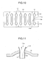
- FIG. 10 is a front view showing a structure for mounting a tube to a header member of a heat exchanger according to one embodiment of the present invention
- FIG. 11 is a cross-sectional view for showing details of the expansion wedge shown in FIG. 10;
- FIG. 12 is a descriptive view showing an angular relationship between the header member and the tube
- FIG. 13 is a descriptive view showing a state in which a core section is transported
- FIG. 14 is a cross-sectional view showing a known method of expanding a tube
- FIG. 15 is a descriptive view showing a tube having a collapsed opening.
- FIG. 16 is a descriptive view showing the deformed state of a tube.
- FIGS. 1 through 3 show an expansion wedge for use with a heat exchanger tube according to the first embodiment of the present invention.
- an aluminum tube 11 having a flat cross section such as that shown in FIG. 4 is inserted into a tube hole 13 a of an aluminum header member 13 , as shown in FIG. 5.
- an expansion wedge 15 is inserted into the opening 11 a of the tube 11 , thereby expanding the cross-sectional width of the opening 11 a and bringing the opening 11 a into close contact with the tube hole 13 a.
- Reference numeral 17 shown in FIGS. 1 through 3 designates a flat expansion wedge body formed from, for example, tool steel.
- An expansion section 19 is integrally formed with the expansion wedge body 17 so as to locate between an upper two-dot chain line A (viz., a chain line wherein each dash is separated by two dots) and a lower two-dot chain line A′ as shown in FIG. 1. Further, a guide protuberance 21 is integrally formed on either longitudinal side of the expansion section 19 so as to protrude upwardly from the two-dot chain line A.
- the expansion section 19 is inserted into the opening 11 a of the tube 11 to a predetermined depth, thus increasing the distance between longitudinal side surfaces 11 b of the opening 11 a.
- the guide protuberances 21 are inserted into the respective sides of the opening 11 a of the tube 11 and guide the expansion section 19 into the opening 11 a, as shown in FIG. 6C.
- the width W A of a cross section taken along the two-dot chain line A spaced distance L A from the apex P is set to be identical with W2, as shown in FIG. 2.
- the guide protuberances 21 are defined between the two-dot chain line A and the apex P.
- a pair of first inclined faces 19 a are formed between the guide protuberances 21 and meet along the longitudinal center axis (a dot line C in FIG. 3) of the expansion section 19 .
- an angle ⁇ 1 between the pair of first inclined faces 19 a is set to be about 77°.
- the distance between the apexes P of the pair of guide protuberances 21 is set such that the apexes P correspond to points P 1 provided inside the tube 11 shown in FIG. 4.
- the tube 11 shown in FIG. 4 is formed from aluminum material having a thickness of 0.25 mm.
- the longitudinal length L of the opening 11 a is set to 25.5 mm, and the width W of the opening 11 a is set to 1.7 mm.
- the expansion edge body 17 has a longitudinal length L1 of 24 mm and a thickness W1 of 4.0 mm, and a distance L2 between the apexes P of the pair of guide protuberances 21 is set to 21.3 mm.
- a pair of second inclined faces 23 are formed on either side of the expansion section 19 so as to extend from the respective apexes P of the guide protuberances 21 and to be formed integrally with the respective first inclined faces 19 a.
- the second inclined faces 23 meet along the longitudinal center axis (a dot line C in FIG. 3) of the expansion section 19 .
- an inclined angle ⁇ 2 of a ridge line PD hereinafter described is set to about 30°.
- a third inclined face 27 is also formed so as to extend outward from the respective apex P of the guide protuberance 21 .
- An inclined angle ⁇ 3 of the third inclined face 27 is set to about 43°.
- a pair of fourth inclined faces 29 are formed on one side of each of the guide protuberances 21 so as to continually extend from the pair of second inclined faces 23 of the guide protuberance 21 .
- the inclined faces 29 meet along the longitudinal center line (a dot line C in FIG. 3) of the expansion section 19 .
- ridge lines PD are formed so as to extend from each of the apexes P of the guide protuberances 21 toward the longitudinal center of the expansion wedge body 17 as well as to either side of the expansion wedge body 17 in the widthwise direction thereof.
- the ridge lines PD come into contact with the interior surfaces of the opening 11 a of the tube 11 , thus expanding the distance between the longitudinal side surfaces 11 b of the opening 11 a of the tube 11 .
- the tube 11 such as that shown in FIG. 4 is inserted into the tube hole 13 a of the header member 13 , as shown in FIG. 5.
- the expansion wedge 15 is inserted into the opening 11 a of the tube 11 , thus expanding the cross-sectional width of the opening 11 a and bringing the opening 11 a into close contact with the tube hole 13 a.
- the expansion wedge 15 is moved toward the tube 11 , so that the apex P of the guide protuberance 21 formed on either longitudinal side of the expansion section 19 is inserted into the respective space 11 c defined in the respective side of the opening 11 a of the tube 11 .
- the pair of ridge lines PD are brought into contact with the interior surfaces of the longitudinal sides of the opening 11 a of the tube 11 , and the distance between the longitudinal sides of the opening 11 a of the tube 11 in respective sides thereof is expanded. As shown in FIG. 6B, the tube 11 eventually becomes deformed, thus ensuring a space 11 d which permits smooth insertion of the expansion section 19 .
- the expansion section 19 is inserted into the space 11 d. As shown in FIGS. 6 C- 6 D, the distance between the longitudinal side surfaces 11 b of the tube 11 is expanded by means of the expansion section 19 .
- FIG. 6D shows a cross-sectional view taken along the line D while the expansion wedge 15 is inserted into the tube 11 , as shown in FIG. 6C.
- FIG. 6B shows a state in which the guide protuberances 21 of the expansion wedge 15 have been inserted into the tube 11 to a depth of 1.5 mm from the respective apexes P.
- FIG. 6C shows a state in which the guide protuberances 21 have been further inserted into the tube 11 to a depth of 1.5 mm from the state of FIG. 6B.
- the expansion operation is terminated after the expansion wedge 15 has been inserted 0.5 mm further into the tube 11 from the state of FIG. 6C.
- the expansion section 19 for expanding the distance between the longitudinal side surfaces 11 b of the tube 11 when being inserted to a predetermined depth into the opening 11 a of the tube 11 is formed on the expansion wedge body 17 .
- the guide protuberances 21 are protrusively formed on the respective longitudinal sides of the expansion section 19 .
- the guide protuberances 21 are inserted into the spaces 11 c provided on the respective sides of the opening 11 a of the tube 11 , thereby guiding the expansion section 19 into the opening 11 a.
- the guide protuberances 21 and the expansion section 19 are prevented from colliding with the edge of the tube 11 , thus readily and thoroughly preventing collapse of the opening 11 a of the tube 11 .
- FIGS. 7 through 9 show an expansion wedge for use with a heat exchanger according to a second embodiment of the present invention.
- Reference numeral 17 A provided in these drawings designates a flat expansion wedge body formed from, example, tool steel.
- An expansion section 19 A is integrally formed with the expansion wedge body 17 A so as to locate between an upper two-dot chain line B and a lower two-dot chain line B′ as shown in FIG. 7. Further, a guide protuberance 21 A is integrally formed on either longitudinal side of the expansion section 19 so as to protrude upwardly from the two-dot chain line B.
- first inclined faces 33 are formed so as to extend from the respective apexes P of the guide protuberances 21 A and meet at the cross-sectional longitudinal center of the expansion wedge body 17 A.
- a pair of second inclined faces 35 are formed so as to continually extend from both sides of the first inclined face 33 and meet at the cross-sectional longitudinal center of the expansion wedge body 17 A.
- third inclined faces 37 are formed so as to extend outward and continually from the respective apexes P of the guide protuberances
- ridge lines PS are formed so as to extend from the respective apexes P of the guide protuberances 31 A toward the longitudinal center of the expansion wedge body 17 A. Further, the ridge lines PS spread to either side in the widthwise direction of the expansion wedge body 17 A.
- the width W B of the cross section taken along line the two-dot chain line B spaced from the apex P by distance L B is set to be identical with W2
- the area defined between the two-chain dot line B and the apex P is taken as the guide protuberance 21 A.
- the expansion section 19 A for expanding the distance between the longitudinal side surfaces 11 b of the tube 11 when inserted to a predetermined depth into the opening 11 a of the tube 11 is formed on the expansion wedge body 17 A.
- the guide protuberances 21 A are protrusively formed on the respective longitudinal sides of the expansion section 19 A.
- the guide protuberances 21 A are inserted into the spaces 11 c provided on the respective sides of the opening 11 a of the tube 11 , thereby guiding the expansion section 19 A into the opening 11 a.
- the guide protuberances 21 and the expansion section 19 A are prevented from colliding with the edge of the tube 11 , thus readily and thoroughly preventing collapse of the opening 11 a of the tube 11 .
- FIG. 10 shows one example of a structure for mounting a tube to a header member of a heat exchanger of the present invention.
- either longitudinal side of the opening 11 a of the tube 11 to be inserted into the tube hole 13 a of the header member 13 is formed so as to have a width greater than that of a center portion 11 e: specifically, an enlarged section 11 f is formed in either longitudinal side of the opening 11 a of the tube 11 .
- the lateral sides of the opening 11 a of the tube 11 are brought into press contact with the tube hole 13 a of the header member 13 .
- the enlarged sections 11 f are formed in the foregoing manner through use of the expansion wedge of the present invention for use with a heater exchanger tube.
- the structure for mounting a tube to a header member of a heat exchanger enables fastening of the tube 11 on the header member 13 .
- the tubes 11 can be reliably mounted on the header member 13 at an angle ⁇ of 90°.
- the mounting structure of the present example enables reliable maintenance of a positional relationship between the header 13 and the tubes 11 .
- the header member 13 can be transported while resting directly on a transport surface 41 .
- the existing mounting structure weak force is applied for retaining the positional relationship between the header member 13 and the tubes 11 .
- weak force is applied for retaining the positional relationship between the header member 13 and the tubes 11 .
- the mounting structure of the present example obviates a necessity for levitating the header member 13 , thus facilitating transportation of the core section 39 .
- the mounting structure reduces the heat capacity of the binding and baking jig 43 , thus enabling efficient baking.
- FIG. 13 schematically shows the core section 39 .
- Reference numeral 45 designates a reinforcement member
- reference numeral 47 designates a corrugated fin.
- the previous embodiments have described a case where the expansion wedge 15 is moved and inserted into the opening 11 a of the tube 11 after the tube 11 has been inserted into the header member 13 .
- the present invention is not limited to such embodiments. For instance, after the expansion wedge 15 has been inserted into the tube hole 13 a of the header member 13 to a predetermined depth, the tube 11 may be moved and the tube hole 13 a may be expanded simultaneous with insertion of the tube 11 into the tube hole 13 a.
- the present invention is not limited to such embodiments.
- the present invention can be broadly applied to a heat exchanger, for example, a condenser.
- the previous embodiments have described a case where a single wedge is formed in the expansion wedge body 17 and a plurality of expansion wedge bodies 17 are incorporated into an assembly machine.
- the present invention is not limited to such embodiments.
- the expansion wedge body 17 may be formed from long plate material, and wedges may be integrally formed on the plate material at intervals.
- the expansion wedge for use with a heat exchanger tube comprises an expansion wedge body on which there is formed the expansion section for expanding the distance between longitudinal side surfaces of the tube when being inserted to a predetermined depth into the opening of the tube, and guide protuberances which are protrusively formed on the respective longitudinal sides of the expansion section and which are inserted into the spaces provided on the respective sides of the opening of the tube, thereby guiding the expansion section into the opening.
- the guide protuberances and the expansion section are prevented from colliding with the edge of the tube, thereby readily and thoroughly preventing collapse of an opening of a tube.
- either longitudinal side of the opening of the tube is made so as to have a width greater than that of a center portion, and the opening is brought into press-contact with the tube hole of the header member. Accordingly, the tube can be firmly attached to the header member.
Landscapes
- Engineering & Computer Science (AREA)
- Mechanical Engineering (AREA)
- Physics & Mathematics (AREA)
- Thermal Sciences (AREA)
- General Engineering & Computer Science (AREA)
- Details Of Heat-Exchange And Heat-Transfer (AREA)
Abstract
An expansion section for expanding the distance between longitudinal side surfaces of an opening of a tube when being inserted a predetermined depth into the opening is formed an expansion wedge body, and guide protuberances are protrusively formed on the respective longitudinal sides of the expansion section. The guide protuberances are inserted into the spaces provided on the respective sides of the opening of the tube, thereby guiding the expansion section into the opening.
Description
- The present application is a divisional of U.S. application Ser. No. 09/511,094, filed Feb. 23, 2000, the entire contents of which are incorporated herein by reference.
- 1. Field of the Invention
- The present invention relates to a structure for mounting a tube to a header member of the heat exchanger which is manufactured through the use of an expansion wedge. The expansion wedge expands the diameter of an opening of a flat tube to be inserted into a tube hole formed in a header member and which brings the opening into close contact with the tube hole.
- The present application is based on Japanese Patent Applications No. Hei. 11-44875 and 2000-23925, which are incorporated herein by reference.
- 2. Description of the Related Art
- According to a known method of manufacturing a heat exchanger, such as a radiator, an opening of a flat tube is expanded while the tube remains inserted into a tube hole formed in a header member, thereby bringing the opening into close contact with the tube hole. Methods described in: for example, Japanese Patent Publication Nos. Sho. 59-180295 and Sho. 60-49861, have already been known as manufacturing methods of this type.
- FIG. 14 shows a manufacturing method described in Japanese Patent Publication No. Sho. 60-49861. According to this method, a
core section 4 is interposed betweenheader members 1 spaced apart from each other by a given distance so as to be mutually oppose. Thecore section 4 is assembled by alternating arrangement oftubes 2 and corrugated fins 3. - Respective ends of the
tubes 2 are inserted intocorresponding tube holes 1 a formed in theheader member 1.Expansion wedges 6 formed on each ofjigs 5 disposed on opposite sides of thecore section 4 are inserted intoopenings 2 a of thetubes 2, thereby bringing theopenings 2 a into close contact with thetube holes 1 a. - Under such a manufacturing method, the
openings 2 a of thetubes 2 are brought into close contact with thetubes holes 1 a, thereby preventing falling of theheader members 1 and abating a solder running failure, which would otherwise frequently arise during a brazing process in a subsequent step. - Under such a known manufacturing method, a portion of the edge of the
opening 2 a of thetube 2 expanded by theexpansion protrusion 6 becomes collapsed, as shown in FIG. 15, thus frequently inducing formation of a collapsedportion 2 b. - In the event that the
tube 2 becomes partially collapsed, coolant circulating through thetube 2 leaks out from the collapsed portion. For this reason, inspection for collapsed portions requires scrupulous attention and a large number of steps. - Considerable research conducted by the present inventor for solving the drawback of the known manufacturing methods shows that, as shown in FIG. 16, a
longitudinal side surface 2 c of thetube 2 becomes inwardly deformed during transportation of thetube 2, introduction of thetubes 2 into an assembly facility, or assembly of thecore section 4 and that, if anexpansion wedge 6 is inserted into theopening 2 a in this state, theexpansion wedge 6 collides deformingly with thelongitudinal side surface 2 c, thus inducing formation of the collapsedportion 2 b. - It is also found that, even when the
longitudinal side surface 2 c becomes deformed, as shown in FIG. 16,spaces 2 d remain present in opposite ends of theflat tube 2. - The present invention has been conceived on the basis of the previously-described finding and is aimed at providing a structure for mounting a tube to a header member in a heat exchanger manufactured through use of an expansion wedge.
- The present invention provides a structure for mounting a tube to a header member of a heat exchanger, by means of inserting an opening of a flat tube into a tube hole of a header member, wherein either longitudinal side of the opening of the tube is made so as to have a width greater than that of a center portion, and the opening is brought into press-contact with the tube hole of the header member.
- The expansion wedge which is used in connection with the present invention, is such that the guide protuberances formed at the respective longitudinal sides of the expansion section are inserted into the spaces provided on the respective sides of the opening of the tube, thereby guiding the expansion section into the opening.
- The expansion section is inserted into the opening, thereby increasing the distance between the longitudinal sides of the opening of the tube. As a result, the opening is brought into close contact with the tube hole.
- In the structure for mounting a tube to a header member, either longitudinal side of the opening of the tube is made so as to have a width greater than that of a center portion, and the respective longitudinal sides of the opening are brought into press-contact with the tube hole of the header member.
- More specifically, a first aspect of the invention resides in a structure for mounting a flat tube to a header member of a heat exchanger, comprising: a tube hole formed in the header member; and an opening of the flat tube being inserted into the tube hole. The open end of the flat tube is expanded in such a manner that both longitudinally opposed sides of the opening of the flat tube have a width greater than widths of any other portion of the flat tube, so that the open end is brought into press-contact with the header member around the tube hole.
- In this instance the tube has an end which is outwardly flared at all portions thereof. Further, the outwardly flared portions of the tube end have a width which is wider than any other portion of the tube. Additionally, the outwardly flared portions of the tube end have a width which is greater than any portion of the tube hole.
- In accordance with the above aspect, the outwardly flared portions of the tube end define a funneled section which has a predetermined angle with respect to a longitudinal axis of the tube.
- Another aspect of the invention resides in a structure for mounting a tube to a header member of heat exchanger wherein the header member has a tube hole and the tube is disposed through the tube hole so that a portion of the tube projects out of and beyond the header member. At least this portion of the tube is outwardly expanded via the insertion of an expansion wedge to establish press-contact between the tube and the tube hole. In accordance with this aspect the tube is a flat tube.
- A further aspect of the invention resides in a structure for mounting a tube to a header member of heat exchanger wherein the header member has a tube hole and the tube is disposed through the tube hole so that a first portion or length of the tube projects out into a space beyond a surface of the header member. The entirety (viz., all of the length) of first portion of tube is outwardly flared via the insertion of an expansion wedge. This insertion also expands and forces a second portion of the tube, which is within the tube hole and which is contiguous with the first portion of tube which becomes outwardly flared, into press-fit contact with the tube hole thus establishing a fluid-tight connection therebetween.
- In accordance with this aspect the portion of the tube which is within the tube hole is in direct surface-to-surface engagement with the tube hole. The tube is a flat tube.
- Yet another aspect of the invention resides in a structure for mounting a tube to a header member of heat exchanger wherein the header member has a tube hole, wherein the flat tube is disposed through the tube hole; and wherein fluid tight connection means for providing a fluid tight connection between the flat tube and the header, is provided between the header member and the flat tube. This fluid tight connection means includes a flared-out tube portion of the tube which extends out beyond the tube hole, and an expanded press-connecting portion within the tube hole which is press fitted or contacted against a surface of the tube hole to form a fluid-tight seal.
- The present invention also features an expansion wedge for use with a heat exchanger tube which increases the cross-sectional width of an opening of a flat tube inserted into a tube hole of a header member through use of an expansion section to be inserted into the opening. This brings the opening into close contact with the tube hole. The expansion wedge comprises: an expansion wedge body on which there is formed the expansion section for expanding the distance between longitudinal side surfaces of the tube when being inserted a predetermined depth into the opening of the tube, and guide protuberances which are protrusively formed on the respective longitudinal sides of the expansion section and which are inserted into the spaces provided on the respective sides of the opening of the tube, thereby guiding the expansion section into the opening.
- Features and advantages of the invention will be evident from the following detailed description of the preferred embodiments described in conjunction with the attached drawings.
- In the accompanying drawings:
- FIG. 1 is a side view showing an expansion wedge for use with a heat exchanger tube according to a first embodiment of the present invention;
- FIG. 2 is a front view of the expansion wedge shown in FIG. 1;
- FIG. 3 is a top view of the expansion wedge shown in FIG. 1;
- FIG. 4 is a descriptive view showing a tube to be expanded by the expansion wedge shown in FIG. 1;
- FIG. 5 is a descriptive view showing a method of increasing the cross-sectional width of the tube through use of the expansion wedge shown in FIG. 1;
- FIGS. 6A-6E show a method of expanding an opening through use of the expansion wedge in a case where a portion of a longitudinal side surface of a tube becomes deformed;
- FIG. 7 is a side view showing an expansion wedge for use with a heat exchanger tube according to a second embodiment of the present invention;
- FIG. 8 is a top view of the expansion wedge shown in FIG. 7;
- FIG. 9 is a front view of the expansion wedge shown in FIG. 7;
- FIG. 10 is a front view showing a structure for mounting a tube to a header member of a heat exchanger according to one embodiment of the present invention;
- FIG. 11 is a cross-sectional view for showing details of the expansion wedge shown in FIG. 10;
- FIG. 12 is a descriptive view showing an angular relationship between the header member and the tube;
- FIG. 13 is a descriptive view showing a state in which a core section is transported;
- FIG. 14 is a cross-sectional view showing a known method of expanding a tube;
- FIG. 15 is a descriptive view showing a tube having a collapsed opening; and
- FIG. 16 is a descriptive view showing the deformed state of a tube.
- The present invention will be described in detail hereinbelow by reference to embodiments shown in the accompanying drawings.
- FIGS. 1 through 3 show an expansion wedge for use with a heat exchanger tube according to the first embodiment of the present invention.
- In the present embodiment, an
aluminum tube 11 having a flat cross section such as that shown in FIG. 4 is inserted into atube hole 13 a of analuminum header member 13, as shown in FIG. 5. In this state, anexpansion wedge 15 is inserted into the opening 11 a of thetube 11, thereby expanding the cross-sectional width of the opening 11 a and bringing the opening 11 a into close contact with thetube hole 13 a. -
Reference numeral 17 shown in FIGS. 1 through 3 designates a flat expansion wedge body formed from, for example, tool steel. - An
expansion section 19 is integrally formed with theexpansion wedge body 17 so as to locate between an upper two-dot chain line A (viz., a chain line wherein each dash is separated by two dots) and a lower two-dot chain line A′ as shown in FIG. 1. Further, aguide protuberance 21 is integrally formed on either longitudinal side of theexpansion section 19 so as to protrude upwardly from the two-dot chain line A. - As shown in FIG. 6C, the
expansion section 19 is inserted into the opening 11 a of thetube 11 to a predetermined depth, thus increasing the distance between longitudinal side surfaces 11 b of the opening 11 a. - Further, as shown in FIG. 6B, the
guide protuberances 21 are inserted into the respective sides of the opening 11 a of thetube 11 and guide theexpansion section 19 into the opening 11 a, as shown in FIG. 6C. - Further, as shown in FIGS. 2 and 4, provided that the shorter distance between interior surfaces of the
tube 11 is taken as W2, the width WA of a cross section taken along the two-dot chain line A spaced distance LA from the apex P is set to be identical with W2, as shown in FIG. 2. The guide protuberances 21 are defined between the two-dot chain line A and the apex P. - In the present embodiment, a pair of first inclined faces 19 a are formed between the
guide protuberances 21 and meet along the longitudinal center axis (a dot line C in FIG. 3) of theexpansion section 19. - As shown in FIG. 2, an angle θ1 between the pair of first inclined faces 19 a is set to be about 77°.
- The distance between the apexes P of the pair of
guide protuberances 21 is set such that the apexes P correspond to points P1 provided inside thetube 11 shown in FIG. 4. - In the present embodiment, the
tube 11 shown in FIG. 4 is formed from aluminum material having a thickness of 0.25 mm. The longitudinal length L of the opening 11 a is set to 25.5 mm, and the width W of the opening 11 a is set to 1.7 mm. - As shown in FIG. 3, the
expansion edge body 17 has a longitudinal length L1 of 24 mm and a thickness W1 of 4.0 mm, and a distance L2 between the apexes P of the pair ofguide protuberances 21 is set to 21.3 mm. - A pair of second inclined faces 23 are formed on either side of the
expansion section 19 so as to extend from the respective apexes P of theguide protuberances 21 and to be formed integrally with the respective first inclined faces 19 a. In each pair of second inclined faces 23, the second inclined faces 23 meet along the longitudinal center axis (a dot line C in FIG. 3) of theexpansion section 19. - As shown in FIG. 1, an inclined angle θ2 of a ridge line PD hereinafter described is set to about 30°.
- As shown in FIG. 1, a third
inclined face 27 is also formed so as to extend outward from the respective apex P of theguide protuberance 21. - An inclined angle θ3 of the third
inclined face 27 is set to about 43°. - As shown in FIGS. 1 and 3, a pair of fourth inclined faces 29 are formed on one side of each of the
guide protuberances 21 so as to continually extend from the pair of second inclined faces 23 of theguide protuberance 21. In each pair of the fourth inclined faces 29, the inclined faces 29 meet along the longitudinal center line (a dot line C in FIG. 3) of theexpansion section 19. - In the present embodiment, ridge lines PD are formed so as to extend from each of the apexes P of the
guide protuberances 21 toward the longitudinal center of theexpansion wedge body 17 as well as to either side of theexpansion wedge body 17 in the widthwise direction thereof. - The ridge lines PD come into contact with the interior surfaces of the opening 11 a of the
tube 11, thus expanding the distance between the longitudinal side surfaces 11 b of the opening 11 a of thetube 11. - The cross-sectional width of the
tube 11 is expanded through use of the previously-describedexpansion wedge 15 in the following manner. - In the present embodiment, the
tube 11 such as that shown in FIG. 4 is inserted into thetube hole 13 a of theheader member 13, as shown in FIG. 5. In this state, theexpansion wedge 15 is inserted into the opening 11 a of thetube 11, thus expanding the cross-sectional width of the opening 11 a and bringing the opening 11 a into close contact with thetube hole 13 a. - In a case where one of the longitudinal side surfaces 11 b of the opening 11 a of the
tube 11 becomes deformed interiorly, as shown in FIG. 6A, the cross-sectional width of thetube 11 is expanded in the following manner. - First, the
expansion wedge 15 is moved toward thetube 11, so that the apex P of theguide protuberance 21 formed on either longitudinal side of theexpansion section 19 is inserted into therespective space 11 c defined in the respective side of the opening 11 a of thetube 11. - As a result of further insertion of the
expansion wedge 15, the pair of ridge lines PD are brought into contact with the interior surfaces of the longitudinal sides of the opening 11 a of thetube 11, and the distance between the longitudinal sides of the opening 11 a of thetube 11 in respective sides thereof is expanded. As shown in FIG. 6B, thetube 11 eventually becomes deformed, thus ensuring aspace 11 d which permits smooth insertion of theexpansion section 19. - Subsequently, as a result of further insertion of the
expansion wedge 15, theexpansion section 19 is inserted into thespace 11 d. As shown in FIGS. 6C-6D, the distance between the longitudinal side surfaces 11 b of thetube 11 is expanded by means of theexpansion section 19. - FIG. 6D shows a cross-sectional view taken along the line D while the
expansion wedge 15 is inserted into thetube 11, as shown in FIG. 6C. - Further insertion of the
expansion wedge 15 into the opening 11 a results in an increase in the overall distance in the longitudinal direction of thetube 11 between the longitudinal side surfaces 11 b of theopening 11 of thetube 11. Accordingly, the opening 11 a is brought into close contact with thetube hole 13 a. - In the present embodiment, FIG. 6B shows a state in which the
guide protuberances 21 of theexpansion wedge 15 have been inserted into thetube 11 to a depth of 1.5 mm from the respective apexes P. FIG. 6C shows a state in which theguide protuberances 21 have been further inserted into thetube 11 to a depth of 1.5 mm from the state of FIG. 6B. - In the present embodiment, the expansion operation is terminated after the
expansion wedge 15 has been inserted 0.5 mm further into thetube 11 from the state of FIG. 6C. - In the
expansion wedge 15 for use with a heat exchanger of the present embodiment, theexpansion section 19 for expanding the distance between the longitudinal side surfaces 11 b of thetube 11 when being inserted to a predetermined depth into the opening 11 a of thetube 11 is formed on theexpansion wedge body 17. Further, theguide protuberances 21 are protrusively formed on the respective longitudinal sides of theexpansion section 19. The guide protuberances 21 are inserted into thespaces 11 c provided on the respective sides of the opening 11 a of thetube 11, thereby guiding theexpansion section 19 into the opening 11 a. As a result, theguide protuberances 21 and theexpansion section 19 are prevented from colliding with the edge of thetube 11, thus readily and thoroughly preventing collapse of the opening 11 a of thetube 11. - FIGS. 7 through 9 show an expansion wedge for use with a heat exchanger according to a second embodiment of the present invention.
-
Reference numeral 17A provided in these drawings designates a flat expansion wedge body formed from, example, tool steel. - An
expansion section 19A is integrally formed with theexpansion wedge body 17A so as to locate between an upper two-dot chain line B and a lower two-dot chain line B′ as shown in FIG. 7. Further, aguide protuberance 21A is integrally formed on either longitudinal side of theexpansion section 19 so as to protrude upwardly from the two-dot chain line B. - In the present embodiment, first inclined faces 33 are formed so as to extend from the respective apexes P of the
guide protuberances 21A and meet at the cross-sectional longitudinal center of theexpansion wedge body 17A. - Further, a pair of second inclined faces 35 are formed so as to continually extend from both sides of the first
inclined face 33 and meet at the cross-sectional longitudinal center of theexpansion wedge body 17A. - As shown in FIG. 7, third inclined faces 37 are formed so as to extend outward and continually from the respective apexes P of the guide protuberances
- More specifically, in the present embodiment, ridge lines PS are formed so as to extend from the respective apexes P of the guide protuberances 31A toward the longitudinal center of the
expansion wedge body 17A. Further, the ridge lines PS spread to either side in the widthwise direction of theexpansion wedge body 17A. - As a result of the ridge lines PS coming into contact with the interior surfaces of the opening 11 a of the
tube 11, the distance between the longitudinal side surfaces 11 b of the opening 11 a of thetube 11 is increased. - As shown in FIG. 4, provided that the shorter diameter between the interior surfaces of the
tube 11 is taken as W2, the width WB of the cross section taken along line the two-dot chain line B spaced from the apex P by distance LB is set to be identical with W2, and the area defined between the two-chain dot line B and the apex P is taken as theguide protuberance 21A. - In the
expansion wedge 17A for use with a heat exchanger of the present embodiment, theexpansion section 19A for expanding the distance between the longitudinal side surfaces 11 b of thetube 11 when inserted to a predetermined depth into the opening 11 a of thetube 11 is formed on theexpansion wedge body 17A. Further, theguide protuberances 21A are protrusively formed on the respective longitudinal sides of theexpansion section 19A. Theguide protuberances 21A are inserted into thespaces 11 c provided on the respective sides of the opening 11 a of thetube 11, thereby guiding theexpansion section 19A into the opening 11 a. As a result, theguide protuberances 21 and theexpansion section 19A are prevented from colliding with the edge of thetube 11, thus readily and thoroughly preventing collapse of the opening 11 a of thetube 11. - FIG. 10 shows one example of a structure for mounting a tube to a header member of a heat exchanger of the present invention. In the present example, either longitudinal side of the opening 11 a of the
tube 11 to be inserted into thetube hole 13 a of theheader member 13 is formed so as to have a width greater than that of acenter portion 11 e: specifically, anenlarged section 11 f is formed in either longitudinal side of the opening 11 a of thetube 11. - As shown in FIG. 11, the lateral sides of the opening 11 a of the
tube 11 are brought into press contact with thetube hole 13 a of theheader member 13. - The
enlarged sections 11 f are formed in the foregoing manner through use of the expansion wedge of the present invention for use with a heater exchanger tube. - The structure for mounting a tube to a header member of a heat exchanger enables fastening of the
tube 11 on theheader member 13. As shown in FIG. 12, thetubes 11 can be reliably mounted on theheader member 13 at an angle θ of 90°. - It has been ascertained that the positional relationship between the
header member 13 and thetubes 11 remains sustained even when the heat exchanger has been subjected to cleansing and passed through a drying furnace, a pre-heating furnace, and a baking furnace after assembly of a core section. - The mounting structure of the present example enables reliable maintenance of a positional relationship between the
header 13 and thetubes 11. As shown in FIG. 13, when acore section 39 is transported horizontally, theheader member 13 can be transported while resting directly on atransport surface 41. - In the existing mounting structure, weak force is applied for retaining the positional relationship between the
header member 13 and thetubes 11. For example, there has been a necessity for taking into consideration protection of theheader member 13 from an external force, by placing on the core section 39 a binding andbaking jig 43 for binding thecore section 39 and by transporting theheader member 13 while levitating the same from atransport surface 41A by means of the binding andbaking jig 43. In contrast, the mounting structure of the present example obviates a necessity for levitating theheader member 13, thus facilitating transportation of thecore section 39. Further, the mounting structure reduces the heat capacity of the binding andbaking jig 43, thus enabling efficient baking. - FIG. 13 schematically shows the
core section 39.Reference numeral 45 designates a reinforcement member, andreference numeral 47 designates a corrugated fin. - The previous embodiments have described a case where the
expansion wedge 15 is moved and inserted into the opening 11 a of thetube 11 after thetube 11 has been inserted into theheader member 13. However, the present invention is not limited to such embodiments. For instance, after theexpansion wedge 15 has been inserted into thetube hole 13 a of theheader member 13 to a predetermined depth, thetube 11 may be moved and thetube hole 13 a may be expanded simultaneous with insertion of thetube 11 into thetube hole 13 a. - Although the previous embodiments have described an example in which the present invention is applied to a radiator, the present invention is not limited to such embodiments. For instance, the present invention can be broadly applied to a heat exchanger, for example, a condenser.
- The previous embodiments have described a case where a single wedge is formed in the
expansion wedge body 17 and a plurality ofexpansion wedge bodies 17 are incorporated into an assembly machine. However, the present invention is not limited to such embodiments. For example, theexpansion wedge body 17 may be formed from long plate material, and wedges may be integrally formed on the plate material at intervals. - As has been described above, the expansion wedge for use with a heat exchanger tube comprises an expansion wedge body on which there is formed the expansion section for expanding the distance between longitudinal side surfaces of the tube when being inserted to a predetermined depth into the opening of the tube, and guide protuberances which are protrusively formed on the respective longitudinal sides of the expansion section and which are inserted into the spaces provided on the respective sides of the opening of the tube, thereby guiding the expansion section into the opening. As a result, the guide protuberances and the expansion section are prevented from colliding with the edge of the tube, thereby readily and thoroughly preventing collapse of an opening of a tube.
- In the structure for mounting a tube to a header member of a heat exchanger, either longitudinal side of the opening of the tube is made so as to have a width greater than that of a center portion, and the opening is brought into press-contact with the tube hole of the header member. Accordingly, the tube can be firmly attached to the header member.
- Although the invention has been described in its preferred form with a certain degree of particularity, it is understood that the present disclosure of the preferred form can be arrangement of parts without departing from the spirit and the scope of the invention as hereinafter claimed.
Claims (7)
1. An expansion wedge for use with a flat heat exchanger tube of which an opening is inserted into a tube hole of a header member, comprising:
an expansion wedge body;
an expansion section for expanding a distance between longitudinal side surfaces of the opening of the tube when being inserted to a predetermined depth into the opening of the tube, to thereby bring the opening into close contact with the tube hole; and
guide protuberances which are protrusively formed on respective longitudinal sides of said expansion section, said guide protuberances being inserted into spaces provided on respective sides of the opening of the tube, thereby guiding the expansion section into the opening.
2. An expansion wedge according to claim 1 , wherein said guide protuberance comprises a plurality of inclined faces which are continuously extended from said expansion section and an apex being formed by collecting corners of said plurality of inclined faces.
3. An expansion wedge according to claim 2 , wherein said guide protuberance comprises five inclined faces.
4. An expansion wedge according to claim 2 , wherein said guide protuberance comprises four inclined faces.
5. An expansion wedge according to claim 1 , wherein a pair of ridge lines are formed so as to extend from an apex of said guide protuberance toward in a widthwise direction of said expansion wedge body.
6. An expansion wedge according to claim 5 , wherein said ridge line extends from said apex to a part of said expansion section across said guide protuberance.
7. An expansion wedge according to claim 5 , wherein said ridge line extends from said apex to said expansion wedge body across said guide protuberance and said expansion section.
Priority Applications (1)
| Application Number | Priority Date | Filing Date | Title |
|---|---|---|---|
| US10/430,337 US6843097B2 (en) | 1999-02-23 | 2003-05-07 | Expansion wedge for use with heat exchanger tube, and structure for mounting tubes to header member of the heat exchange |
Applications Claiming Priority (6)
| Application Number | Priority Date | Filing Date | Title |
|---|---|---|---|
| JP11-044875 | 1999-02-23 | ||
| JP4487599 | 1999-02-23 | ||
| JP2000023925A JP3905278B2 (en) | 1999-02-23 | 2000-02-01 | Mounting structure of tube to header member in heat exchanger tube mouth claw and heat exchanger |
| JP2000-023925 | 2000-02-01 | ||
| US09/511,094 US6572153B2 (en) | 1999-02-23 | 2000-02-23 | Structure for mounting tubes to header member of a heat exchanger |
| US10/430,337 US6843097B2 (en) | 1999-02-23 | 2003-05-07 | Expansion wedge for use with heat exchanger tube, and structure for mounting tubes to header member of the heat exchange |
Related Parent Applications (1)
| Application Number | Title | Priority Date | Filing Date |
|---|---|---|---|
| US09/511,094 Division US6572153B2 (en) | 1999-02-23 | 2000-02-23 | Structure for mounting tubes to header member of a heat exchanger |
Publications (2)
| Publication Number | Publication Date |
|---|---|
| US20030197370A1 true US20030197370A1 (en) | 2003-10-23 |
| US6843097B2 US6843097B2 (en) | 2005-01-18 |
Family
ID=26384846
Family Applications (2)
| Application Number | Title | Priority Date | Filing Date |
|---|---|---|---|
| US09/511,094 Expired - Fee Related US6572153B2 (en) | 1999-02-23 | 2000-02-23 | Structure for mounting tubes to header member of a heat exchanger |
| US10/430,337 Expired - Fee Related US6843097B2 (en) | 1999-02-23 | 2003-05-07 | Expansion wedge for use with heat exchanger tube, and structure for mounting tubes to header member of the heat exchange |
Family Applications Before (1)
| Application Number | Title | Priority Date | Filing Date |
|---|---|---|---|
| US09/511,094 Expired - Fee Related US6572153B2 (en) | 1999-02-23 | 2000-02-23 | Structure for mounting tubes to header member of a heat exchanger |
Country Status (3)
| Country | Link |
|---|---|
| US (2) | US6572153B2 (en) |
| JP (1) | JP3905278B2 (en) |
| GB (1) | GB2347203B (en) |
Cited By (1)
| Publication number | Priority date | Publication date | Assignee | Title |
|---|---|---|---|---|
| US20060225873A1 (en) * | 2005-04-07 | 2006-10-12 | Fuller Christopher A | Heat exchanger assembly having fitting secured thereto and method of securing the same |
Families Citing this family (14)
| Publication number | Priority date | Publication date | Assignee | Title |
|---|---|---|---|---|
| JP3905278B2 (en) * | 1999-02-23 | 2007-04-18 | カルソニックカンセイ株式会社 | Mounting structure of tube to header member in heat exchanger tube mouth claw and heat exchanger |
| US20020098056A1 (en) * | 2001-01-22 | 2002-07-25 | Progressive Stamping Company, Inc. | Method of attaching a plate to a rod and assembly |
| DE10322211A1 (en) * | 2003-05-16 | 2004-12-02 | Modine Manufacturing Co., Racine | heat exchanger block |
| US7461689B2 (en) * | 2004-06-01 | 2008-12-09 | Modine Manufacturing Company | Thermal cycling resistant tube to header joint for heat exchangers |
| JP4970795B2 (en) * | 2006-01-16 | 2012-07-11 | 株式会社日本クライメイトシステムズ | Heat exchanger manufacturing jig and heat exchanger manufacturing method using the manufacturing jig |
| US8118085B2 (en) * | 2008-02-06 | 2012-02-21 | Leprino Foods Company | Heat exchanger |
| US9309839B2 (en) | 2010-03-18 | 2016-04-12 | Modine Manufacturing Company | Heat exchanger and method of manufacturing the same |
| AU2011201083B2 (en) * | 2010-03-18 | 2013-12-05 | Modine Manufacturing Company | Heat exchanger and method of manufacturing the same |
| DE102013212939A1 (en) * | 2013-07-03 | 2015-01-08 | Behr Gmbh & Co. Kg | Production method for a heat exchanger and tool for producing the heat exchanger |
| DE102014206612A1 (en) * | 2014-04-04 | 2015-10-29 | Mahle International Gmbh | heat exchangers |
| FR3037643B1 (en) * | 2015-06-22 | 2019-07-12 | Valeo Systemes Thermiques | HEAT EXCHANGER AND METHOD FOR MANUFACTURING THE SAME |
| FR3060728B1 (en) * | 2016-12-19 | 2019-05-17 | Valeo Systemes Thermiques | HEAT EXCHANGER AND METHOD FOR MANUFACTURING THE SAME |
| CN107322287A (en) * | 2017-08-11 | 2017-11-07 | 成都领专科技有限责任公司 | A kind of guiding part |
| CN107283148A (en) * | 2017-08-11 | 2017-10-24 | 成都领专科技有限责任公司 | A kind of guiding part |
Citations (11)
| Publication number | Priority date | Publication date | Assignee | Title |
|---|---|---|---|---|
| US341554A (en) * | 1886-05-11 | Tube-packing for surface-condensers | ||
| US685866A (en) * | 1899-10-28 | 1901-11-05 | Thomas K Maher | Water and steam tight joint. |
| US1500560A (en) * | 1921-04-09 | 1924-07-08 | Albert E L Henderson | Radiator-tube joint |
| US1502301A (en) * | 1922-09-06 | 1924-07-22 | Fedders Mfg Co Inc | Radiator |
| US1719847A (en) * | 1927-02-28 | 1929-07-09 | American Blower Corp | Method of forming radiators |
| US3940837A (en) * | 1973-11-30 | 1976-03-02 | The Singer Company | Hot air furnace with improved heat exchanger construction |
| US3964873A (en) * | 1971-12-07 | 1976-06-22 | Mitsubishi Jukogyo Kabushiki Kaisha | Heating device having dumbbell-shaped reaction tubes therein |
| US4369837A (en) * | 1980-02-08 | 1983-01-25 | Societe Anonyme Des Usines Chausson | Tube for tube-plate heat exchangers |
| US5787973A (en) * | 1995-05-30 | 1998-08-04 | Sanden Corporation | Heat exchanger |
| US6263570B1 (en) * | 1996-03-29 | 2001-07-24 | Valeo Engine Cooling Aktiebolag | Heat exchanger and method of producing the same |
| US6460610B2 (en) * | 1999-03-10 | 2002-10-08 | Transpro, Inc. | Welded heat exchanger with grommet construction |
Family Cites Families (10)
| Publication number | Priority date | Publication date | Assignee | Title |
|---|---|---|---|---|
| GB560205A (en) * | 1942-09-23 | 1944-03-24 | York Raising & Dyeing Company | Improvements relating to the formation of sockets on the ends of metal pipes and tubes |
| GB822092A (en) * | 1956-08-10 | 1959-10-21 | Imp Brass Mfg Co | Tube flaring tool |
| FR2402850A1 (en) * | 1977-09-09 | 1979-04-06 | Ferodo Sa | FINNED TUBE DEVICE FOR A HEAT EXCHANGER, IN PARTICULAR FOR A MOTOR VEHICLE RADIATOR, AND THE MANUFACTURING PROCESS |
| JPS6049861A (en) | 1983-08-30 | 1985-03-19 | Nippon Radiator Co Ltd | Production of heat exchanger core |
| DE4026988C2 (en) | 1990-08-25 | 1999-10-28 | Behr Gmbh & Co | Heat exchanger with a package of flat tubes and corrugated fin units |
| JPH0649861A (en) * | 1992-07-30 | 1994-02-22 | Taisei Corp | Earth and sand conveying method with air pressure |
| DE4446754A1 (en) | 1994-12-24 | 1996-06-27 | Behr Gmbh & Co | Method for construction of heat exchanger |
| JP3905278B2 (en) * | 1999-02-23 | 2007-04-18 | カルソニックカンセイ株式会社 | Mounting structure of tube to header member in heat exchanger tube mouth claw and heat exchanger |
| JP3027581B1 (en) * | 1999-06-21 | 2000-04-04 | 株式会社三五 | Pipe material expansion processing method and pipe material expansion processing device |
| JP4582887B2 (en) * | 2000-09-25 | 2010-11-17 | 日新製鋼株式会社 | Manufacturing method of metal pipe having end of eccentric diameter expansion pipe |
-
2000
- 2000-02-01 JP JP2000023925A patent/JP3905278B2/en not_active Expired - Fee Related
- 2000-02-22 GB GB0004202A patent/GB2347203B/en not_active Expired - Fee Related
- 2000-02-23 US US09/511,094 patent/US6572153B2/en not_active Expired - Fee Related
-
2003
- 2003-05-07 US US10/430,337 patent/US6843097B2/en not_active Expired - Fee Related
Patent Citations (11)
| Publication number | Priority date | Publication date | Assignee | Title |
|---|---|---|---|---|
| US341554A (en) * | 1886-05-11 | Tube-packing for surface-condensers | ||
| US685866A (en) * | 1899-10-28 | 1901-11-05 | Thomas K Maher | Water and steam tight joint. |
| US1500560A (en) * | 1921-04-09 | 1924-07-08 | Albert E L Henderson | Radiator-tube joint |
| US1502301A (en) * | 1922-09-06 | 1924-07-22 | Fedders Mfg Co Inc | Radiator |
| US1719847A (en) * | 1927-02-28 | 1929-07-09 | American Blower Corp | Method of forming radiators |
| US3964873A (en) * | 1971-12-07 | 1976-06-22 | Mitsubishi Jukogyo Kabushiki Kaisha | Heating device having dumbbell-shaped reaction tubes therein |
| US3940837A (en) * | 1973-11-30 | 1976-03-02 | The Singer Company | Hot air furnace with improved heat exchanger construction |
| US4369837A (en) * | 1980-02-08 | 1983-01-25 | Societe Anonyme Des Usines Chausson | Tube for tube-plate heat exchangers |
| US5787973A (en) * | 1995-05-30 | 1998-08-04 | Sanden Corporation | Heat exchanger |
| US6263570B1 (en) * | 1996-03-29 | 2001-07-24 | Valeo Engine Cooling Aktiebolag | Heat exchanger and method of producing the same |
| US6460610B2 (en) * | 1999-03-10 | 2002-10-08 | Transpro, Inc. | Welded heat exchanger with grommet construction |
Cited By (2)
| Publication number | Priority date | Publication date | Assignee | Title |
|---|---|---|---|---|
| US20060225873A1 (en) * | 2005-04-07 | 2006-10-12 | Fuller Christopher A | Heat exchanger assembly having fitting secured thereto and method of securing the same |
| US7213640B2 (en) | 2005-04-07 | 2007-05-08 | Delphi Technologies, Inc. | Heat exchanger assembly having fitting secured thereto and method of securing the same |
Also Published As
| Publication number | Publication date |
|---|---|
| JP2000312939A (en) | 2000-11-14 |
| GB2347203B (en) | 2001-11-07 |
| GB2347203A (en) | 2000-08-30 |
| JP3905278B2 (en) | 2007-04-18 |
| GB0004202D0 (en) | 2000-04-12 |
| US6572153B2 (en) | 2003-06-03 |
| US20020149202A1 (en) | 2002-10-17 |
| US6843097B2 (en) | 2005-01-18 |
Similar Documents
| Publication | Publication Date | Title |
|---|---|---|
| US6843097B2 (en) | Expansion wedge for use with heat exchanger tube, and structure for mounting tubes to header member of the heat exchange | |
| US6397937B1 (en) | Heat exchanger and a method for producing a heat exchanger | |
| EP0641986B1 (en) | Heat exchanger and method for manufacturing thereof | |
| EP0745824B1 (en) | Heat exchanger and method for manufacturing the same | |
| US6718860B2 (en) | Method and apparatus for making holes in pipe | |
| US5535820A (en) | Method for assembling a heat exchanger | |
| CZ303129B6 (en) | Heat exchanger and process for producing the heat exchanger | |
| JP4985127B2 (en) | Heat exchanger and manufacturing method thereof | |
| KR100920289B1 (en) | A heat exchanger and a method of manufacturing a heat exchanger manifold | |
| KR20090041465A (en) | Connector pipe for condenser | |
| CN100342201C (en) | Heat transfer device and method of manufacturing the same | |
| US6115918A (en) | Heat exchanger manifold separator installation method | |
| JPH087247Y2 (en) | Heat exchanger | |
| GB2358242A (en) | Mounting of flat tube a header member of a heat exchanger | |
| JP5062067B2 (en) | Heat exchanger | |
| JP2002346742A (en) | Brazing method | |
| JPH11230691A5 (en) | ||
| JPH0740866Y2 (en) | End plate structure of heat exchanger | |
| KR100972927B1 (en) | Combined structure of end cap and side support of condenser | |
| JPH0552565U (en) | Heat exchanger | |
| JP4985234B2 (en) | Heat exchanger and manufacturing method thereof | |
| JPH0451252B2 (en) | ||
| JP4218349B2 (en) | Heat exchanger | |
| JPH085280A (en) | Aluminum material heat exchanger | |
| JP2009138992A (en) | Heat exchanger |
Legal Events
| Date | Code | Title | Description |
|---|---|---|---|
| FEPP | Fee payment procedure |
Free format text: PAYOR NUMBER ASSIGNED (ORIGINAL EVENT CODE: ASPN); ENTITY STATUS OF PATENT OWNER: LARGE ENTITY |
|
| FPAY | Fee payment |
Year of fee payment: 4 |
|
| REMI | Maintenance fee reminder mailed | ||
| LAPS | Lapse for failure to pay maintenance fees | ||
| STCH | Information on status: patent discontinuation |
Free format text: PATENT EXPIRED DUE TO NONPAYMENT OF MAINTENANCE FEES UNDER 37 CFR 1.362 |
|
| FP | Lapsed due to failure to pay maintenance fee |
Effective date: 20130118 |