US20030196723A1 - Container and plug for container - Google Patents
Container and plug for container Download PDFInfo
- Publication number
- US20030196723A1 US20030196723A1 US10/434,562 US43456203A US2003196723A1 US 20030196723 A1 US20030196723 A1 US 20030196723A1 US 43456203 A US43456203 A US 43456203A US 2003196723 A1 US2003196723 A1 US 2003196723A1
- Authority
- US
- United States
- Prior art keywords
- section
- path
- plug
- cap
- gas
- Prior art date
- Legal status (The legal status is an assumption and is not a legal conclusion. Google has not performed a legal analysis and makes no representation as to the accuracy of the status listed.)
- Granted
Links
Images


Classifications
-
- B—PERFORMING OPERATIONS; TRANSPORTING
- B67—OPENING, CLOSING OR CLEANING BOTTLES, JARS OR SIMILAR CONTAINERS; LIQUID HANDLING
- B67D—DISPENSING, DELIVERING OR TRANSFERRING LIQUIDS, NOT OTHERWISE PROVIDED FOR
- B67D1/00—Apparatus or devices for dispensing beverages on draught
- B67D1/08—Details
- B67D1/0829—Keg connection means
- B67D1/0831—Keg connection means combined with valves
- B67D1/0835—Keg connection means combined with valves with one valve
-
- B—PERFORMING OPERATIONS; TRANSPORTING
- B65—CONVEYING; PACKING; STORING; HANDLING THIN OR FILAMENTARY MATERIAL
- B65D—CONTAINERS FOR STORAGE OR TRANSPORT OF ARTICLES OR MATERIALS, e.g. BAGS, BARRELS, BOTTLES, BOXES, CANS, CARTONS, CRATES, DRUMS, JARS, TANKS, HOPPERS, FORWARDING CONTAINERS; ACCESSORIES, CLOSURES, OR FITTINGS THEREFOR; PACKAGING ELEMENTS; PACKAGES
- B65D11/00—Containers having bodies formed by interconnecting or uniting two or more rigid, or substantially rigid, components made wholly or mainly of plastics material
- B65D11/02—Containers having bodies formed by interconnecting or uniting two or more rigid, or substantially rigid, components made wholly or mainly of plastics material of curved cross-section
- B65D11/06—Drums or barrels
- B65D11/08—Arrangements of filling or discharging apertures
-
- B—PERFORMING OPERATIONS; TRANSPORTING
- B67—OPENING, CLOSING OR CLEANING BOTTLES, JARS OR SIMILAR CONTAINERS; LIQUID HANDLING
- B67D—DISPENSING, DELIVERING OR TRANSFERRING LIQUIDS, NOT OTHERWISE PROVIDED FOR
- B67D7/00—Apparatus or devices for transferring liquids from bulk storage containers or reservoirs into vehicles or into portable containers, e.g. for retail sale purposes
- B67D7/02—Apparatus or devices for transferring liquids from bulk storage containers or reservoirs into vehicles or into portable containers, e.g. for retail sale purposes for transferring liquids other than fuel or lubricants
- B67D7/0288—Container connection means
-
- Y—GENERAL TAGGING OF NEW TECHNOLOGICAL DEVELOPMENTS; GENERAL TAGGING OF CROSS-SECTIONAL TECHNOLOGIES SPANNING OVER SEVERAL SECTIONS OF THE IPC; TECHNICAL SUBJECTS COVERED BY FORMER USPC CROSS-REFERENCE ART COLLECTIONS [XRACs] AND DIGESTS
- Y10—TECHNICAL SUBJECTS COVERED BY FORMER USPC
- Y10T—TECHNICAL SUBJECTS COVERED BY FORMER US CLASSIFICATION
- Y10T137/00—Fluid handling
- Y10T137/8593—Systems
- Y10T137/86292—System with plural openings, one a gas vent or access opening
- Y10T137/86324—Tank with gas vent and inlet or outlet
- Y10T137/86332—Vent and inlet or outlet in unitary mounting
-
- Y—GENERAL TAGGING OF NEW TECHNOLOGICAL DEVELOPMENTS; GENERAL TAGGING OF CROSS-SECTIONAL TECHNOLOGIES SPANNING OVER SEVERAL SECTIONS OF THE IPC; TECHNICAL SUBJECTS COVERED BY FORMER USPC CROSS-REFERENCE ART COLLECTIONS [XRACs] AND DIGESTS
- Y10—TECHNICAL SUBJECTS COVERED BY FORMER USPC
- Y10T—TECHNICAL SUBJECTS COVERED BY FORMER US CLASSIFICATION
- Y10T137/00—Fluid handling
- Y10T137/8593—Systems
- Y10T137/86292—System with plural openings, one a gas vent or access opening
- Y10T137/8634—With vented outlet
-
- Y—GENERAL TAGGING OF NEW TECHNOLOGICAL DEVELOPMENTS; GENERAL TAGGING OF CROSS-SECTIONAL TECHNOLOGIES SPANNING OVER SEVERAL SECTIONS OF THE IPC; TECHNICAL SUBJECTS COVERED BY FORMER USPC CROSS-REFERENCE ART COLLECTIONS [XRACs] AND DIGESTS
- Y10—TECHNICAL SUBJECTS COVERED BY FORMER USPC
- Y10T—TECHNICAL SUBJECTS COVERED BY FORMER US CLASSIFICATION
- Y10T137/00—Fluid handling
- Y10T137/8593—Systems
- Y10T137/86348—Tank with internally extending flow guide, pipe or conduit
Definitions
- the present invention relates to a container which stores liquids such as highly purified chemicals for semiconductors and ordinary chemical agents, and a plug for such a container.
- plugs 2 each of which has a plug section (not shown in the drawing) are positioned in these openings la.
- These plugs 2 function as lids which close the openings la, one is a plug 2 a for connection to the liquid path, and the other one is a plug 2 b for connection to the gas path, and a pipe 3 which extends to the vicinity of the bottom of the container 1 is connected to the liquid path plug 2 a for connection to the liquid path.
- a cap is put on the plug sections of each plug 2 positioned in the openings la in this type of container 1 , the through hole which is formed in the plug section is closed by this cap, and the liquid in this container is carried or stored in this state.
- inert gas is fed into the container 1 from the hose 4 which is connected to the plug section of the plug 2 b on the other side in such a way that the pressure inside of the container 1 is not negative. Also, it can be determined by the flow of gas on the gas drawing-side whether all the liquid inside the container 1 was fed out and whether the container 1 has become empty. Consequently, when a gas flow is detected, it is determined that the inside of the container 1 is empty, and this empty container 1 can be replaced by a new container 1 in which liquid is stored.
- a sign is placed on the plug 2 a on which the pipe 3 is provided indicating that the plug 2 a is to be used for connection with the liquid path, and a sign is placed on the other plug 2 b on which pipe 3 is not provided, indicating that the plug 2 b is to be used for connection with the gas path.
- An operator detaches the cap put on the plug section of plug 2 a for connection with liquid path, after identifying the signs on these plugs 2 a and 2 b and taking out the cap which was put on the plug section of plug 2 a for connection with the gas path from the plug in order to lower the internal pressure of the container 1 .
- the present invention was made in light of the above situation, and an object of the present invention is to a provide a container and plugs for the container with greater safety such that liquid does not leak due to the internal pressure during use.
- the container ( 1 ) has a container body ( 10 ), at least one liquid path plug ( 11 ) and at least one gas path plug ( 12 ) which are attached to openings ( 10 a ) formed in the container body ( 10 ).
- the liquid path plug ( 11 ) has a lid section ( 14 ) attached to the opening ( 1 a ) in a watertight manner.
- a liquid path plug section ( 16 b ) having a through hole ( 16 a ) which communicates with an inner space of the container body and a pipe ( 17 ) which is connected to the liquid path plug section ( 16 b ).
- a liquid path plug section ( 16 b ) is provided in the container body, and a liquid path cap ( 22 ) is detachably attached to the liquid path plug section ( 16 b ) to block the through hole ( 16 a ).
- the gas path plug ( 12 ) has a lid section ( 14 ) attached to the opening ( 10 a ) in a watertight manner, and a gas path plug section ( 16 c ) having a through hole ( 16 a ) communicating with the inner space of the container body, and a gas path cap ( 22 ) which is detachably attached to the gas path plug section ( 16 c ) to block the through hole ( 16 a ).
- the gas path cap ( 22 ) has a disengaging section ( 35 ) which can be used to detach the liquid path cap ( 22 ) from the liquid path plug section.
- the gas path cap can be detached using the detaching fixture.
- the plug section is formed as a cylinder in which the through hole is formed in the center, the liquid path cap and the gas path cap are positioned covering the plug sections and the liquid path cap and the gas path cap are formed as cylinders having a bottom section such that the through hole of the plug section is closed.
- the container according to a third aspect by respectively covering the plug section formed as a cylinder with the liquid path cap and the gas path cap which are cylinders with bottom sections, and by positioning the liquid path cap and the gas path cap on the plug sections, it is possible to securely and easily seal the through hole of the plug section of the container when carrying and storing.
- a container as described in the third aspect has a male thread formed on the external surface of the plug section, a female thread which can engage the male thread of the plug section is formed on the internal surface on liquid path cap and the gas path cap, and by engaging the female thread to the male thread, the liquid path cap and the gas path cap are fitted into the plug section.
- an engaging device which engage by means of convexo-concave interfitting is provided between the detaching fixture and the gas path cap, and between the gas path cap and the liquid path cap.
- an engaging pin is provided on the detaching fixture so as to fit to an engaging hole section which is formed on the end surface of the gas path cap.
- An engaging protrusion section is formed on the gas path cap so as to fit to an engaging groove section formed on the end surface of the liquid path cap.
- An engaging device is constructed by respectively engaging the engaging pin with the engaging hole section, and the engaging hole section with the engaging groove section.
- the container according to a sixth aspect by fitting the engaging pin of the detaching fixture into the engaging hole of the gas path cap and by turning the engaging pin, it is possible to unscrew the gas path cap using the detaching fixture and to detach the gas path cap quite easily, also by fitting the engaging protrusion section of the gas path cap into the engaging groove section of the liquid path cap and by turning the engaging protrusion section, it is possible to unscrew the liquid path cap using the gas path cap and detach the liquid path cap quite easily.
- a gas removal path which is closed by the cap which is fitted and communicates between the external surface and the bottom surface of the lid section is formed in the plug section of the liquid path plug, and when detaching the liquid path cap, the gas removal path is opened before the through hole.
- the opening of the gas removal path formed in the plug section is opened, and the inside of the container communicates with the outside of the container before the through hole of the plug section is opened when detaching the liquid path cap, and problems such that liquid passes through the pipe and leaks from the through hole can be securely prevented.
- the plug which is used in the container described in an eighth aspect of present invention is characterized in that the lid section is attached to an opening of the container, the plug section has a through hole which is fixed to the lid section and connects the inside and the outside of the container, and a gas removal path is fixed to the lid section ( 14 ) and connects the inside and the outside of the container.
- a pipe connects the through hole which is provided in the plug section, a cap is fixed to the plug section, and closes the through hole and the gas removal path.
- the gas removal path is provided in the position such that the opening of the gas removal path is opened before the through hole is opened when detaching the cap.
- the gas removal path formed in the plug section is opened before the through hole is opened, and the inside of the container communicates with the outside of the container; therefore, the difference in the pressure is nullified even if the inside pressure of the container increases, and problems such that the liquid passes through the pipe and leaks from the through hole can be more securely avoided.
- the plug section is formed as a cylinder in which the through hole is formed in the center, the gas removal path is opened on the external surface of the plug section, the cap is formed as a cylinder with a bottom section which covers the plug, a sealing material which seals the gap between the plug and the cap provided on the internal surface.
- the male thread is formed on the external surface of the plug on the plug section
- the female thread which can be screwed with the male thread of the plug section is formed on the internal surface of the cap, and by screwing the male thread into the female thread, the cap is fixed to the plug section.
- the sealing material provided in the internal surface of the cap moves towards the farther side of the top of the plug section than the opening of the gas removal path, the gas removal path is opened before the through hole is opened, the difference in the pressure between the inside and the outside of the container is nullified, and problems such that the liquid passes through the pipe and leaks from the through hole can be securely prevented.
- FIG. 1 is a cross section of the container for explaining the container according to the first embodiment of present invention.
- FIG. 2 is a cross section of the liquid path plug for explaining the organization and the construction of the liquid path plug used in the container according to the first embodiment of present invention.
- FIG. 3 is a plan view of the liquid path plug for explaining the shape of the liquid path cap which is put on the plug section of the liquid path plug used in the container according to the first embodiment of present invention.
- FIG. 4 is a perspective view of the liquid path cap for explaining the shape of the liquid path cap which is put on the plug section of the liquid path plug used in the container according to the first embodiment of present invention.
- FIG. 5 is a cross section of the gas path plug for explaining the organization and the construction of the gas path plug used in the container according to the first embodiment of present invention.
- FIG. 6 is a plan view of the gas path plug for explaining the shape of the gas path cap which is put on the plug section of the gas path plug used in the container according to the first embodiment of present invention.
- FIG. 7 is a perspective view of the gas path cap for explaining the shape of the gas path cap which is used on the plug section of the gas path plug used in the container according to the first embodiment of present invention.
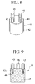
- FIG. 8 is a perspective view of the detaching fixture for explaining the detaching fixture which detaches the gas path cap which has been put on the plug section of the gas path plug used in the container according to the first embodiment of present invention.
- FIG. 9 is a cross section of the detaching fixture for explaining the detaching fixture which detaches the gas path cap which has been put on the plug section of the gas path plug used in the container according to the first aspect of present invention.
- FIG. 10 is a cross section of the gas path plug for explaining the detaching method of the gas path cap which has been put on the plug section of the gas path plug of the container according to the first aspect of present invention.
- FIG. 11 is a cross section of the liquid path plug for explaining the detaching method of the liquid path cap which is put on the plug section of the liquid path plug of the container according to the first embodiment of present invention.
- FIG. 12 is a cross section of the plug section and the socket explaining the construction of the socket which is connected to the plug section of the liquid path plug of the container according to the first embodiment of present invention.
- FIG. 13 is a cross section of the plug section and socket, both of which are connected to each other, for explaining the connecting construction of the plug section of the liquid path plug and the socket of the container according to the first embodiment of present invention.
- FIG. 14 is a cross section of the liquid path plug for explaining the organization and the construction of the liquid path plug according to the second aspect of present invention.
- FIG. 15 is a cross section of the liquid path plug for explaining the function of the liquid path plug according to the second aspect of present invention.
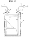
- FIG. 16 is a cross section of the container for explaining the method of drawing out the liquid from the container in which the liquid is stored.
- the reference numeral 10 is the container.
- this container 10 two openings 10 a are formed, and a liquid path plug 11 and a gas path plug 12 which are both uniformly formed from synthetic resin are fitted into these openings 10 a .
- the liquid path plug 11 and the gas path plug 12 function as lids which respectively close the openings 10 a of the container 10 .
- liquid path plug 11 has a lid section 14 which is attached by being screwed into opening 10 a of the container 10 , and a liquid path plug section 16 b which is provided so as to protrude at the center of the concave section 15 formed on the lid section 14 , and a pipe 17 which is formed in the lower part of the lid section 14 .
- the liquid path plug section 16 b is formed as a cylinder having a through hole 16 a in the center, and the liquid path plug section 16 b is integrally formed with the lid section 14 .
- a stopping groove 18 which is formed in the shape of a ring extends in the circumferential direction is formed in the external surface of the liquid path plug section 16 b , and when connecting the socket 5 to the liquid path plug section 16 b , a locking ball 79 which will be explained later becomes engaged in the stopping groove 18 .
- the top side of this stopping groove 18 is formed extending in the circumferential direction, the top side of this stopping groove 18 is made to be catching projection 19 which pushes the locking ball 79 and which will be explained later.
- the pipe 17 is formed as a long cylinder having a passage 17 a in the center, the pipe 17 is integrally formed in the lower section of the lid section 14 in the same way as in the liquid path plug section 16 b . Additionally, the passage 17 a of this pipe 17 and the through hole 16 a of the liquid path plug section 16 b communicate with each other. The length of this pipe 17 is formed such that the bottom edge section of the pipe 17 is disposed near the bottom section of the container 10 when screwing and fixing the lid section 14 has been screwed into and fixed to the opening 10 a of the container 10 . Additionally, this pipe 17 can be formed separately from the lid section 14 and welded to the lid section 14 .
- the lid section 14 has, on the external surface of the top edge section of the lid section 14 , a male thread section 14 a which can be screwed into the female thread section 10 b which is formed on the opening 10 a of the container 10 .
- a male thread section 14 a By screwing this male thread section 14 a into the female thread section 10 b of the opening 10 a , the lid section 14 is fixed to the opening 10 a of the container 10 .
- the O-ring 14 b is provided in the lower side of the male thread section 14 a on the lid section 14 , when fixing the lid section 14 on the opening 10 a , the gaps between these opening 10 a and the lid section 14 is sealed by the 0 -ring 14 b.
- a male thread 21 is formed on the external surface near the base of the liquid path plug section 16 b , and a female thread 23 formed on the internal surface of the edge side of the opening of the liquid path cap 22 which is formed as a cylinder having a bottom section screws onto the male thread 21 .
- An 0 -ring 24 (sealing material) is provided on the internal surface of this liquid path cap 22 .
- this liquid path cap 22 is attached to the liquid path plug section 16 b .
- the O-ring 24 provided on the internal surface sticks to the external surface of the liquid path plug section 16 b , and the liquid path plug section 16 b is perfectly sealed.
- the engaging groove sections 25 (engaging device) having the shape of a cross are formed on both edges of this liquid path cap 22 .
- the gas path plug 12 is constructed in almost the same way as the liquid path plug 11 which is explained above, and structures similar to those of the liquid path plug 11 are indicated with the same reference numerals and explanation for them will be emitted.
- the pipe 17 is not formed in this gas path plug 12 . Furthermore, a plurality of hole sections 31 are formed in the edge section of the plug section 16 .
- the male thread 21 is formed in the external surface near the base of the gas path plug section 16 c of this gas path plug 12 , and a female thread 33 formed on the inside surface of the opening edge section side of the gas path cap 32 formed as a cylinder having a bottom section is screwed into this male thread 21 .
- the O-ring 34 is provided on the bottom surface of this gas path cap 32 , by covering the gas path plug section 16 c with the gas path cap 32 , and by screwing the female thread 33 onto the male thread 21 of the gas path plug section 16 c , this gas path cap 32 is attached to the gas path plug section 16 c , the 0 -ring 34 formed on the bottom surface makes contact with the end surface of the gas path plug section 16 c , and the gas path plug section 16 c is perfectly sealed.
- an engaging protrusion section (engaging device) 35 in the shape of a cross is formed in the end surface of this gas path cap 32 , and a plurality of engaging hole sections 36 (engaging device) are formed leaving an interval in the circumferential direction.
- the gas path cap 32 attached to the gas path plug section 16 c of the gas path plug 12 is detached.
- the detaching fixture 41 is used as shown in FIGS. 8 and 9.
- This detaching fixture 41 comprises a fixture body 42 which is formed in a pillar shape and a plurality of engaging pins 43 provided in the end surface of this fixture body 42 , and the side peripheral surface of the fixture body 42 is formed in a fine saw-tooth shape, in other words a Knurled shape.
- the gas path cap 32 which has already been detached is used. More specifically, in the state that this gas path cap 32 is clamped, as shown in FIG. 11, the engaging protrusion section 35 formed in the end surface of the gas path cap 32 is fitted to the engaging groove section 25 formed in the end surface of the liquid path cap 22 , and is turned to the direction of unscrewing.
- the socket 5 has a main cylinder body 51 inside of which a valve hole 52 is formed.
- a stopper 53 is fixed at the rear end section.
- a male thread section 56 of the end section of the valve member 55 formed in a bar shape is screwed and fixed into the female thread section 54 formed in the center of the stopper.
- a narrow part 55 a is formed near the end of this valve member 55 , and a valve 55 b having a large diameter is formed closer to the end of this valve member 55 than this narrow part 55 a.
- a step section 55 c is formed on the narrow section 55 a side in this valve 55 b.
- a bellows member 57 is provided in the valve hole 52 .
- This bellows member 57 is formed as a cylinder having a bellows member 58 formed such that it has a cross section at the center section, and the bellows member 57 can extend and shrink in the axis direction at the bellows member 58 . Additionally, the rear end section of this bellows member 57 is clamped and fixed between the external surface of the stopper 53 and the internal surface of the main cylinder body 51 .
- a valve boss section 59 is formed on the top side of this bellows member 57 .
- This valve boss section 59 has a hole section 61 in the center, the top side of this hole section 61 is formed with a larger diameter, and this section is made to be a step section 62 .
- a spring 63 is provided between the stopper 53 and the valve boss section 59 of the bellows member 57 , the valve boss section 59 of the bellows member 57 is always pushed towards the top side by this spring 63 , by this pushing force, the valve 55 b of the valve member 55 is fitted in the hole section 61 of the valve boss section 59 , and the gap between the valve 55 b and the valve boss section 59 is closed.
- a plurality of paths 64 are formed in the circular direction on the stopper 53 , and the hose 4 side and the inside of the bellows member 57 communicates by these paths 64 .
- O-ring 65 is provided over the circular direction in the top surface of the valve boss section 59 .
- a concave section 71 is formed on the top side of the main cylinder body 51 , it is provided such that the plug section 16 b is fitted into this concave section 71 .
- a sleeve 72 is provided which is able to slide on the external surface of the main cylinder body 51 . Detachment of the sleeve 72 from the top section of the main cylinder body 51 is prevented by the stop ring 73 formed on the top section of the main cylinder body 51 .
- a prong part 74 is provided in the internal surface side near the end section of this sleeve 72 , a push ring 76 and a spring 77 are provided between this prong part 74 and a step section 75 formed on the external surface of the main cylinder body 51 . Consequently, the sleeve 72 is always pushed towards the direction of the end section of the main cylinder body 51 by this spring 77 .
- the hole section 78 is a long hole in a mortar shape and is formed with an interval towards the circular direction near the end section of the main cylinder body 51 , and the lock ball 79 is provided in this hole section 78 .
- the lock ball 79 is made to be able to move into and appear out of the internal surface side of the concave section 71 of the main cylinder body 51 , when moving the sleeve 72 to the top section side by the pushing force of the spring 77 , the lock ball 79 is pushed into the internal surface side by the prong part 74 of the sleeve 72 , and is maintained such that a part of the lock ball 79 projects from the concave section 71 .
- valve boss section 59 of the bellows member 57 and the valve 55 b of the valve member 55 separate , a path is formed between them, and the hose 4 connected to the socket 5 and the passage 17 a of the pipe 17 communicate.
- the socket 5 to which the hose 4 which supplies the inert gas into the container 10 is connected is combined with the gas path plug section 16 c of the gas path plug 12 .
- the inert gas is fed from the hose 4 of the socket 5 connected with the gas path plug 12 of the opening 10 a on the other side, and stored in the container 10 a , and the pressure inside the container 10 does not become negative.
- gaps between the detaching fixture 41 and the gas path cap 32 , and between the gas path cap 32 and the liquid path cap 22 are constructed to engage each other by convexo-concave interfitting, it is possible to carry out the detaching operation of the liquid path cap 22 and the gas path cap 32 easily.
- a plurality of gas removal paths 81 connect through with the surrounding surface near the upper end of the liquid path plug section 16 b and the bottom surface of the lid section 14 are formed on the liquid path plug 11 for connection with the liquid path with an interval towards the circumference direction.
- a plurality of gas removal holes 82 are formed between the female thread 23 and the O-ring 24 on the liquid path cap (cap) 22 attached to the liquid path plug section 16 b of this liquid path plug 11 .
- the opening 81 a on the surrounding surface of the liquid path plug section 16 b of the gas removal path 81 formed on the liquid path plug section 16 b is formed at a position which disposes the opening 81 a at a lower side of the liquid path cap 22 than the O-ring 24 in the state that the liquid path cap 22 is attached to this liquid path plug section 16 b.
- liquid path cap 22 of the above second embodiment can be used in combination with the container 10 of the first embodiment.
Landscapes
- Engineering & Computer Science (AREA)
- Mechanical Engineering (AREA)
- Closures For Containers (AREA)
- Filling Or Discharging Of Gas Storage Vessels (AREA)
- Quick-Acting Or Multi-Walled Pipe Joints (AREA)
Abstract
The object of this invention is to improve safety by preventing the leakage of liquid caused by the internal pressure of a container. A liquid path plug in which a pipe is provided in the lid section of the plug, and a gas path plug which does not have a pipe are attached to openings of the container. The engaging groove section is formed on the end surface of the liquid path cap which closes the through hole provided in the liquid path plug section of the liquid path plug. The engaging protrusion section and the engaging hole section are formed on the end surface of the gas path cap which is provided in the gas path plug section of the gas path plug and closes the through hole. The gas path cap is detached by engaging the engaging pin of the detaching fixture on the engaging hole section of the gas path cap and by turning the gas path cap. The liquid path cap is detached by engaging the engaging protrusion section of the detached gas path cap on the engaging groove section of the liquid path cap and by turning the gas path cap.
Description
- This application is a divisional application of U.S. non-provisional patent application Ser. No. 09/975,595, entitled “Container and Plug for Container,” filed on Oct. 10, 2001.
- 1. Field of the Invention
- The present invention relates to a container which stores liquids such as highly purified chemicals for semiconductors and ordinary chemical agents, and a plug for such a container.
- 2. Description of the Related Art
- Generally, a semiconductor high pure chemical and an ordinary chemical agent are stored in containers which are resistable to such agents.
- Formally, as shown in FIG. 16, two openings la are formed in this container 1,
plugs 2 each of which has a plug section (not shown in the drawing) are positioned in these openings la. Theseplugs 2 function as lids which close the openings la, one is a plug 2 a for connection to the liquid path, and the other one is aplug 2 b for connection to the gas path, and apipe 3 which extends to the vicinity of the bottom of the container 1 is connected to the liquid path plug 2 a for connection to the liquid path. - Also, a cap is put on the plug sections of each
plug 2 positioned in the openings la in this type of container 1, the through hole which is formed in the plug section is closed by this cap, and the liquid in this container is carried or stored in this state. - Consequently, when taking out the liquids stored in this container 1, firstly, after the caps which had been put on the plug sections of the
plugs 2 which were positioned in the openings la are removed,sockets 5 connected withhoses 4 are connected to the plug sections of theseplugs 2, and the liquid inside the container 1 is drawn out into thehose 4 by way of the pipe by a pump P. - Additionally, at this time, inert gas is fed into the container 1 from the
hose 4 which is connected to the plug section of theplug 2 b on the other side in such a way that the pressure inside of the container 1 is not negative. Also, it can be determined by the flow of gas on the gas drawing-side whether all the liquid inside the container 1 was fed out and whether the container 1 has become empty. Consequently, when a gas flow is detected, it is determined that the inside of the container 1 is empty, and this empty container 1 can be replaced by a new container 1 in which liquid is stored. - There are the cases in which the liquid inside the container 1 vaporizes as time goes by, so there is concern that the internal pressure increases during use. This occurs particularly when the liquid inside the container 1 is volatile.
- Therefore, if the cap of the plug section of plug 2 a for connection with the liquid path is detached when the internal pressure is high in this way, there is concern that the liquid will leak travel along the way of the
pipe 3 and leak from the through hole of the plug section because of the internal pressure of the container 1. - For this reason, a sign is placed on the plug 2 a on which the
pipe 3 is provided indicating that the plug 2 a is to be used for connection with the liquid path, and a sign is placed on theother plug 2 b on whichpipe 3 is not provided, indicating that theplug 2 b is to be used for connection with the gas path. An operator detaches the cap put on the plug section of plug 2 a for connection with liquid path, after identifying the signs on theseplugs 2 a and 2 b and taking out the cap which was put on the plug section of plug 2 a for connection with the gas path from the plug in order to lower the internal pressure of the container 1. - However, with the above container 1, the removal of the caps in turn has to be performed only according to the signs on the
plugs 2 a and 2 b; therefore an improvement in safety is desired. - The present invention was made in light of the above situation, and an object of the present invention is to a provide a container and plugs for the container with greater safety such that liquid does not leak due to the internal pressure during use.
- In order to achieve the above object, the container ( 1) according to a first aspect of present invention has a container body (10), at least one liquid path plug (11) and at least one gas path plug (12) which are attached to openings (10 a) formed in the container body (10). The liquid path plug (11) has a lid section (14) attached to the opening (1 a) in a watertight manner. A liquid path plug section (16 b) having a through hole (16 a) which communicates with an inner space of the container body and a pipe (17) which is connected to the liquid path plug section (16 b). A liquid path plug section (16 b) is provided in the container body, and a liquid path cap (22) is detachably attached to the liquid path plug section (16 b) to block the through hole (16 a). The gas path plug (12) has a lid section (14) attached to the opening (10 a) in a watertight manner, and a gas path plug section (16 c) having a through hole (16 a) communicating with the inner space of the container body, and a gas path cap (22) which is detachably attached to the gas path plug section (16 c) to block the through hole (16 a). The gas path cap (22) has a disengaging section (35) which can be used to detach the liquid path cap (22) from the liquid path plug section.
- In the container according to the first aspect, when drawing out the liquid inside the container by detaching the liquid path cap and the gas path cap which respectively close the through holes of the plug sections of the liquid path plug and the gas path plug fitted in the openings, because the liquid path cap is made detachable by means of the gas path cap which is detached from the plug section of the gas path plug. When detaching each cap in order to draw out the liquid inside the container, the detaching of the liquid path cap is always done after detaching the gas path cap. As a result, even if the internal pressure increases due to the vaporization of the liquid inside the container, when detaching the liquid path cap, the difference in the pressure between the inside and the outside of the container is nullified because the gas path cap of the gas path plug has already been detached. Therefore, problems such that the liquid inside the container passes along the pipe and leaks from the through hole of the plug can be securely eliminated.
- More specifically, by performing above detaching steps, it is possible to quite easily detach the gas path cap and the liquid path cap from the gas path plug and the liquid path plug, connect the socket to which the hose is connected, and draw out the liquid inside the container.
- In the container according to a second aspect of present invention, the gas path cap can be detached using the detaching fixture.
- More specifically, when detaching the gas path cap which is put on the gas path plug section, because the detaching fixture is used, the step of opening the liquid path cap and the gas path cap is securely carried out; therefore safety can be further improved.
- In the container according to a third aspect of present invention, the plug section is formed as a cylinder in which the through hole is formed in the center, the liquid path cap and the gas path cap are positioned covering the plug sections and the liquid path cap and the gas path cap are formed as cylinders having a bottom section such that the through hole of the plug section is closed.
- More specifically, by putting respectively the liquid path cap which is formed as a cylinder which has a bottom section and the gas path cap on the plug section which is formed as a cylinder, it is possible to securely and easily seal the through holes of the plug sections of the container when carrying and storing..
- With the container according to a third aspect, by respectively covering the plug section formed as a cylinder with the liquid path cap and the gas path cap which are cylinders with bottom sections, and by positioning the liquid path cap and the gas path cap on the plug sections, it is possible to securely and easily seal the through hole of the plug section of the container when carrying and storing.
- In the container according to a fourth aspect of present invention, in a container as described in the third aspect has a male thread formed on the external surface of the plug section, a female thread which can engage the male thread of the plug section is formed on the internal surface on liquid path cap and the gas path cap, and by engaging the female thread to the male thread, the liquid path cap and the gas path cap are fitted into the plug section.
- More specifically, by respectively twisting the liquid path cap side thread and gas path cap with respect to the plug sections, attachment and detachment of the liquid path cap and the gas path cap to and from the plug sections can be carried out easily.
- In the container according to a fourth aspect, by turning respectively the liquid path cap and the gas path cap with respect to the plug sections, it is possible to quite easily attach the liquid path cap and the gas path cap to the plug sections and to detach the liquid path cap and the gas path cap from the plug sections.
- In the container according to a fifth aspect of present invention, an engaging device which engage by means of convexo-concave interfitting is provided between the detaching fixture and the gas path cap, and between the gas path cap and the liquid path cap.
- In this way, because the construction is such that the convexo-concave interfitting is provided between the detaching fixture and the gas path cap, and between the gas path cap and the liquid path cap, the operation of detaching the liquid path cap and the gas path cap can be easily performed.
- In the container according to a sixth aspect of present invention, an engaging pin is provided on the detaching fixture so as to fit to an engaging hole section which is formed on the end surface of the gas path cap. An engaging protrusion section is formed on the gas path cap so as to fit to an engaging groove section formed on the end surface of the liquid path cap. An engaging device is constructed by respectively engaging the engaging pin with the engaging hole section, and the engaging hole section with the engaging groove section.
- More specifically, by fitting the engaging pin of the detaching fixture into the engaging hole section of the gas path cap and by turning the engaging pin, it is possible to quite easily unscrew and detach the gas path cap using the detaching fixture, also by fitting the engaging protrusion section of the gas path cap into the engaged groove of the liquid path cap and by turning the engaging protrusion section, it is possible to quite easily unscrew and detach the liquid path cap using the gas path cap.
- In the container according to a sixth aspect, by fitting the engaging pin of the detaching fixture into the engaging hole of the gas path cap and by turning the engaging pin, it is possible to unscrew the gas path cap using the detaching fixture and to detach the gas path cap quite easily, also by fitting the engaging protrusion section of the gas path cap into the engaging groove section of the liquid path cap and by turning the engaging protrusion section, it is possible to unscrew the liquid path cap using the gas path cap and detach the liquid path cap quite easily.
- In the container according to a seventh aspect of present invention, a gas removal path which is closed by the cap which is fitted and communicates between the external surface and the bottom surface of the lid section is formed in the plug section of the liquid path plug, and when detaching the liquid path cap, the gas removal path is opened before the through hole.
- In this way, even if in the worst case the internal pressure of the container increases when detaching the liquid path cap, when the liquid path cap is detached, the opening of the gas removal path formed in the plug section is opened and the inside of the container communicates with the outside of the container before the through hole of the plug section is opened, and problems that the liquid passes along the pipe and leaks from the through hole can be more securely avoided.
- Accordingly, if an operator tries to detach the liquid path cap of the plug section of the liquid path plug of other container by using the gas path cap which is detached from the plug section of the gas path plug of the container, the leak of the liquid from the through hole of the plug section due to the internal pressure of the container can be securely prevented.
- In the container according to the seventh aspect, even if the internal pressure of the container increases for whatever reason, when detaching the liquid path cap, the opening of the gas removal path formed in the plug section is opened, and the inside of the container communicates with the outside of the container before the through hole of the plug section is opened when detaching the liquid path cap, and problems such that liquid passes through the pipe and leaks from the through hole can be securely prevented.
- Accordingly, even if an operator tries to detach the liquid path cap of the plug section of the liquid path plug of other container using the gas path cap detached from the plug section of the gas path plug of the container, it is possible to prevent securely the leakage of liquid from the through hole of the plug section due to the internal pressure of the container.
- The plug which is used in the container described in an eighth aspect of present invention is characterized in that the lid section is attached to an opening of the container, the plug section has a through hole which is fixed to the lid section and connects the inside and the outside of the container, and a gas removal path is fixed to the lid section ( 14) and connects the inside and the outside of the container. A pipe connects the through hole which is provided in the plug section, a cap is fixed to the plug section, and closes the through hole and the gas removal path. The gas removal path is provided in the position such that the opening of the gas removal path is opened before the through hole is opened when detaching the cap.
- More specifically, when opening the through hole of the plug section by detaching the cap, the gas removal path formed in the plug section is opened before the through hole is opened, and the inside of the container communicates with the outside of the container; therefore, the difference in the pressure is nullified even if the inside pressure of the container increases, and problems such that the liquid passes through the pipe and leaks from the through hole can be more securely avoided.
- In the plug according to a ninth aspect of present invention, the plug section is formed as a cylinder in which the through hole is formed in the center, the gas removal path is opened on the external surface of the plug section, the cap is formed as a cylinder with a bottom section which covers the plug, a sealing material which seals the gap between the plug and the cap provided on the internal surface. When moving the cap which is fitted to the plug in the direction of the top of the plug in order to detach the cap, by moving the sealing material further forward the top of the plug section than the opening of the gas removal path, the gas removal path is opened before the through hole is opened.
- More specifically, when moving the cap towards the top of the plug in order to detach the cap, because the sealing material provided on the internal surface of the cap moves to the farther side of the top of the plug than the opening part of the gas removal path, the gas removal path is opened before the through hole is opened, the difference in the pressure between the inside and the outside of the container is nullified, and problems such that the liquid passes through the pipe and leaks from the through hole can be more securely avoided.
- In the plug according to a tenth aspect of present invention, the male thread is formed on the external surface of the plug on the plug section, the female thread which can be screwed with the male thread of the plug section is formed on the internal surface of the cap, and by screwing the male thread into the female thread, the cap is fixed to the plug section.
- In this way, when detaching the cap which has been screwed into the plug section by unscrewing the cap, the sealing material provided in the internal surface of the cap moves towards the farther side of the top of the plug than the opening of the gas removal path, and the gas removal path is opened before the through hole is opened; therefore, the difference in the pressure between the inside and the outside of the container is nullified, and problems such that the liquid passes through the pipes and leaks from the through hole can be more securely avoided.
- Also, by covering the plug section by the cap and by screwing the cap into the plug section, it is quite easily possible to put the cap on the plug section, close the through hole and the gas removal path, and perform the carrying the container and the storing the liquid in the container.
- In the plug which is used in the container according to the tenth aspect, when unscrewing the cap which has been screwed onto the plug section and detaching the cap, the sealing material provided in the internal surface of the cap moves towards the farther side of the top of the plug section than the opening of the gas removal path, the gas removal path is opened before the through hole is opened, the difference in the pressure between the inside and the outside of the container is nullified, and problems such that the liquid passes through the pipe and leaks from the through hole can be securely prevented.
- Also, by covering the plug section with the cap and by screwing the cap onto the plug section, it is possible to put the cap on the plug section, close the through hole and the gas removal path, carrying the container and store the liquid quite easily.
- FIG. 1 is a cross section of the container for explaining the container according to the first embodiment of present invention.
- FIG. 2 is a cross section of the liquid path plug for explaining the organization and the construction of the liquid path plug used in the container according to the first embodiment of present invention.
- FIG. 3 is a plan view of the liquid path plug for explaining the shape of the liquid path cap which is put on the plug section of the liquid path plug used in the container according to the first embodiment of present invention.
- FIG. 4 is a perspective view of the liquid path cap for explaining the shape of the liquid path cap which is put on the plug section of the liquid path plug used in the container according to the first embodiment of present invention.
- FIG. 5 is a cross section of the gas path plug for explaining the organization and the construction of the gas path plug used in the container according to the first embodiment of present invention.
- FIG. 6 is a plan view of the gas path plug for explaining the shape of the gas path cap which is put on the plug section of the gas path plug used in the container according to the first embodiment of present invention.
- FIG. 7 is a perspective view of the gas path cap for explaining the shape of the gas path cap which is used on the plug section of the gas path plug used in the container according to the first embodiment of present invention.
- FIG. 8 is a perspective view of the detaching fixture for explaining the detaching fixture which detaches the gas path cap which has been put on the plug section of the gas path plug used in the container according to the first embodiment of present invention.
- FIG. 9 is a cross section of the detaching fixture for explaining the detaching fixture which detaches the gas path cap which has been put on the plug section of the gas path plug used in the container according to the first aspect of present invention. FIG. 10 is a cross section of the gas path plug for explaining the detaching method of the gas path cap which has been put on the plug section of the gas path plug of the container according to the first aspect of present invention.
- FIG. 11 is a cross section of the liquid path plug for explaining the detaching method of the liquid path cap which is put on the plug section of the liquid path plug of the container according to the first embodiment of present invention.
- FIG. 12 is a cross section of the plug section and the socket explaining the construction of the socket which is connected to the plug section of the liquid path plug of the container according to the first embodiment of present invention.
- FIG. 13 is a cross section of the plug section and socket, both of which are connected to each other, for explaining the connecting construction of the plug section of the liquid path plug and the socket of the container according to the first embodiment of present invention.
- FIG. 14 is a cross section of the liquid path plug for explaining the organization and the construction of the liquid path plug according to the second aspect of present invention.
- FIG. 15 is a cross section of the liquid path plug for explaining the function of the liquid path plug according to the second aspect of present invention.
- FIG. 16 is a cross section of the container for explaining the method of drawing out the liquid from the container in which the liquid is stored.
- The container and the plug for the container according to the embodiments of present invention are explained with reference to the drawings.
- First Embodiment
- In FIG. 1, the
reference numeral 10 is the container. In thiscontainer 10, twoopenings 10 a are formed, and a liquid path plug 11 and a gas path plug 12 which are both uniformly formed from synthetic resin are fitted into theseopenings 10 a. In addition, the liquid path plug 11 and the gas path plug 12 function as lids which respectively close theopenings 10 a of thecontainer 10. - Next, the liquid path plug 11 and the gas path plug 12 are respectively explained. As shown in FIG. 2, liquid path plug 11 has a
lid section 14 which is attached by being screwed into opening 10 a of thecontainer 10, and a liquid path plugsection 16 b which is provided so as to protrude at the center of theconcave section 15 formed on thelid section 14, and apipe 17 which is formed in the lower part of thelid section 14. - The liquid path plug
section 16 b is formed as a cylinder having a throughhole 16 a in the center, and the liquid path plugsection 16 b is integrally formed with thelid section 14. In this liquid path plugsection 16 b, a stoppinggroove 18 which is formed in the shape of a ring extends in the circumferential direction is formed in the external surface of the liquid path plugsection 16 b, and when connecting thesocket 5 to the liquid path plugsection 16 b, a lockingball 79 which will be explained later becomes engaged in the stoppinggroove 18. Also the top side of this stoppinggroove 18 is formed extending in the circumferential direction, the top side of this stoppinggroove 18 is made to be catchingprojection 19 which pushes the lockingball 79 and which will be explained later. - Also, the
pipe 17 is formed as a long cylinder having apassage 17 a in the center, thepipe 17 is integrally formed in the lower section of thelid section 14 in the same way as in the liquid path plugsection 16 b. Additionally, thepassage 17 a of thispipe 17 and the throughhole 16 a of the liquid path plugsection 16 b communicate with each other. The length of thispipe 17 is formed such that the bottom edge section of thepipe 17 is disposed near the bottom section of thecontainer 10 when screwing and fixing thelid section 14 has been screwed into and fixed to theopening 10 a of thecontainer 10. Additionally, thispipe 17 can be formed separately from thelid section 14 and welded to thelid section 14. - The
lid section 14 has, on the external surface of the top edge section of thelid section 14, amale thread section 14 a which can be screwed into thefemale thread section 10 b which is formed on theopening 10 a of thecontainer 10. By screwing thismale thread section 14 a into thefemale thread section 10 b of the opening 10 a, thelid section 14 is fixed to theopening 10 a of thecontainer 10. Additionally the O-ring 14 b is provided in the lower side of themale thread section 14 a on thelid section 14, when fixing thelid section 14 on theopening 10 a, the gaps between these opening 10 a and thelid section 14 is sealed by the 0-ring 14 b. - Also, a
male thread 21 is formed on the external surface near the base of the liquid path plugsection 16 b, and afemale thread 23 formed on the internal surface of the edge side of the opening of the liquid path cap 22 which is formed as a cylinder having a bottom section screws onto themale thread 21. - An 0-ring 24 (sealing material) is provided on the internal surface of this liquid path cap 22. By covering the liquid path plug
section 16 b with this liquid path cap 22, and by screwing thefemale thread 23 onto themale thread 21 of the liquid path plugsection 16 b, this liquid path cap 22 is attached to the liquid path plugsection 16 b. The O-ring 24 provided on the internal surface sticks to the external surface of the liquid path plugsection 16 b, and the liquid path plugsection 16 b is perfectly sealed. - Also, as shown in FIGS. 3 and 4, the engaging groove sections 25 (engaging device) having the shape of a cross are formed on both edges of this liquid path cap 22.
- As shown in FIG. 5, the gas path plug 12 is constructed in almost the same way as the liquid path plug 11 which is explained above, and structures similar to those of the liquid path plug 11 are indicated with the same reference numerals and explanation for them will be emitted.
- The
pipe 17 is not formed in this gas path plug 12. Furthermore, a plurality ofhole sections 31 are formed in the edge section of theplug section 16. - Additionally, the
male thread 21 is formed in the external surface near the base of the gas path plugsection 16 c of this gas path plug 12, and afemale thread 33 formed on the inside surface of the opening edge section side of the gas path cap 32 formed as a cylinder having a bottom section is screwed into thismale thread 21. - The O-
ring 34 is provided on the bottom surface of thisgas path cap 32, by covering the gas path plugsection 16 c with thegas path cap 32, and by screwing thefemale thread 33 onto themale thread 21 of the gas path plugsection 16 c, this gas path cap 32 is attached to the gas path plugsection 16 c, the 0-ring 34 formed on the bottom surface makes contact with the end surface of the gas path plugsection 16 c, and the gas path plugsection 16 c is perfectly sealed. - Also, as shown in FIGS. 6 and 7, an engaging protrusion section (engaging device) 35 in the shape of a cross is formed in the end surface of this
gas path cap 32, and a plurality of engaging hole sections 36 (engaging device) are formed leaving an interval in the circumferential direction. - Consequently, in order to take out the liquid stored in
above container 10 in which the liquid path plug 11 and the gas path plug 12 have been attached to theopening 10 a of thecontainer 10, the gas path cap 32 attached to the gas path plugsection 16 c of the gas path plug 12 is detached, thehole section 31 of the gas path plugsection 16 c of the gas path plug 12 is opened, and the difference in the pressure between the inside and the outside of thecontainer 10 is nullified. After that, the liquid path cap 22 attached to the liquid path plugsection 16 b of the liquid path plug 11 is detached, thesocket 5 to which ahose 4 is connected is connected to therespective plug section 16. - Next, for a
container 10 of above construction, a detailed explanation will be made for the case of drawing out the liquid inside thecontainer 10 by connectingsockets 5, to which thehoses 4 are connected, respectively to the liquid path plugsection 16 b of the liquid path plug 11 and the gas path plug 12 which are attached to theopenings 10 a. - The Detaching of the Gas Path Cap
- First, the gas path cap 32 attached to the gas path plug
section 16 c of the gas path plug 12 is detached. In order to detach thisgas path cap 32, the detachingfixture 41 is used as shown in FIGS. 8 and 9. - This detaching
fixture 41 comprises afixture body 42 which is formed in a pillar shape and a plurality of engagingpins 43 provided in the end surface of thisfixture body 42, and the side peripheral surface of thefixture body 42 is formed in a fine saw-tooth shape, in other words a Knurled shape. - On this
fixture body 42, fourthread holes 44 are formed on the end surface at an interval in the circular direction, and athread section 43 a formed on the engagingpin 43 is screwed into thisthread hole 44, and is fixed to thisthread hole 44. - Consequently, in order to detach the gas path cap 32 using this detaching
fixture 41, in the state that thefixture body 42 of this detachingfixture 41 is clamped, as shown in FIG. 10, the engagingpin 43 fits into the engaginghole section 36 formed on the end surface of thegas path cap 32, and the engagingpin 43 is turned in the direction of unscrewing. - By doing it in this way, the gas path cap 32 which has been screwed into the
male thread 21 of the gas path plugsection 16 c is unscrewed and then the gas path cap 32 is detached. - Consequently, when this gas path cap 32 is unscrewed and detached, the inside of the
container 10 communicates with the outside of the container by way of the throughhole 16 a of the gas path plugsection 16 c of the gas path plug 12. - By this step, even if the internal pressure increases due to the vaporization of the liquid inside the
container 10, by detaching thegas path cap 32, gas inside thecontainer 10 flows to the outside of thecontainer 10, and the difference in the pressure between the inside and the outside of thecontainer 10 is nullified. - The Detaching of the Liquid Path Cap
- Next, the liquid path cap 22 attached to the liquid path plug
section 16 b of the liquid path plug 11 is detached. - In order to detach this liquid path cap 22, the gas path cap 32 which has already been detached is used. More specifically, in the state that this gas path cap 32 is clamped, as shown in FIG. 11, the engaging
protrusion section 35 formed in the end surface of the gas path cap 32 is fitted to the engaginggroove section 25 formed in the end surface of the liquid path cap 22, and is turned to the direction of unscrewing. - By doing it in this way, the liquid path cap 22 which was screwed into the
male thread 21 of the liquid path plugsection 16 b is unscrewed and detached. At this time, any pressure difference between the inside of thecontainer 10 and the outside is eliminated because the gas path cap 32 of the gas path plug 12 has already been detached, and the liquid from inside thecontainer 10 does not pass through thepipe 17 and leak from the throughhole 16 a of the liquid path plugsection 16 b. - By performing the above steps, it is possible quite safely to detach the gas path cap 32 and the liquid path cap 22 from the gas path plug 12 and the liquid path plug 11, connect the
socket 5 to which thehose 4 is connected, and take out the liquid inside thecontainer 10. - Here, the connected construction of the
plug sections socket 5 will be explained by taking an example of the liquid path plug 11. - As shown in FIG. 12, the
socket 5 has amain cylinder body 51 inside of which avalve hole 52 is formed. In thevalve hole 52 of thismain cylinder body 51, astopper 53 is fixed at the rear end section. In thisstopper 53, amale thread section 56 of the end section of thevalve member 55 formed in a bar shape is screwed and fixed into thefemale thread section 54 formed in the center of the stopper. - A
narrow part 55 a is formed near the end of thisvalve member 55, and avalve 55 b having a large diameter is formed closer to the end of thisvalve member 55 than thisnarrow part 55 a. - Also, a
step section 55 c is formed on thenarrow section 55 a side in thisvalve 55 b. - Also, a
bellows member 57 is provided in thevalve hole 52. This bellowsmember 57 is formed as a cylinder having abellows member 58 formed such that it has a cross section at the center section, and thebellows member 57 can extend and shrink in the axis direction at thebellows member 58. Additionally, the rear end section of this bellowsmember 57 is clamped and fixed between the external surface of thestopper 53 and the internal surface of themain cylinder body 51. Also, avalve boss section 59 is formed on the top side of this bellowsmember 57. Thisvalve boss section 59 has ahole section 61 in the center, the top side of thishole section 61 is formed with a larger diameter, and this section is made to be astep section 62. - Also, a
spring 63 is provided between thestopper 53 and thevalve boss section 59 of thebellows member 57, thevalve boss section 59 of thebellows member 57 is always pushed towards the top side by thisspring 63, by this pushing force, thevalve 55 b of thevalve member 55 is fitted in thehole section 61 of thevalve boss section 59, and the gap between thevalve 55 b and thevalve boss section 59 is closed. - Also, a plurality of
paths 64 are formed in the circular direction on thestopper 53, and thehose 4 side and the inside of thebellows member 57 communicates by thesepaths 64. - Additionally, O-
ring 65 is provided over the circular direction in the top surface of thevalve boss section 59. - Also, a
concave section 71 is formed on the top side of themain cylinder body 51, it is provided such that theplug section 16 b is fitted into thisconcave section 71. Also, asleeve 72 is provided which is able to slide on the external surface of themain cylinder body 51. Detachment of thesleeve 72 from the top section of themain cylinder body 51 is prevented by thestop ring 73 formed on the top section of themain cylinder body 51. Aprong part 74 is provided in the internal surface side near the end section of thissleeve 72, apush ring 76 and aspring 77 are provided between thisprong part 74 and astep section 75 formed on the external surface of themain cylinder body 51. Consequently, thesleeve 72 is always pushed towards the direction of the end section of themain cylinder body 51 by thisspring 77. - Also, the
hole section 78 is a long hole in a mortar shape and is formed with an interval towards the circular direction near the end section of themain cylinder body 51, and thelock ball 79 is provided in thishole section 78. - Consequently, in the state that the
sleeve 72 is moved in the direction of the rear end section of themain cylinder body 51, thelock ball 79 is made to be able to move into and appear out of the internal surface side of theconcave section 71 of themain cylinder body 51, when moving thesleeve 72 to the top section side by the pushing force of thespring 77, thelock ball 79 is pushed into the internal surface side by theprong part 74 of thesleeve 72, and is maintained such that a part of thelock ball 79 projects from theconcave section 71. - Consequently, by pushing the
socket 5 of above construction into the liquid path plugsection 16 b, as shown in FIG. 13, thesocket 5 can be connected to theplug section 16 by hand with a single operation. - Here, this connection method is explained.
- When the
socket 5 is pushed into the liquid path plugsection 16 b, firstly thelock ball 79 of thesocket 5 makes contact with the catchingprojection 19 of theplug section 16. If thesocket 5 is pushed further, thelock ball 79 projects to the external circumference side due to the catchingprojection 19. Thereby, thepush ring 76 provided in the external circumference side of thelock ball 79 resists the pushing force of thespring 77 and is moved to the rear end side of thesocket 5. Thereby, thelock ball 79 enters the gap made between thepush ring 76 and theprong part 74 of thesleeve 72. - When the
socket 5 is pushed into the liquid path plugsection 16 b further and thelock ball 79 overreaches the catchingprojection 19, thelock ball 79 which is pushed towards the internal surface side of theconcave section 71 by thespring 77 by way of thepush ring 76 projects to the internal surface side of theconcave section 71 and enters into the stoppinggroove 18, also thepush ring 76 is moved to the top edge side of thesocket 5 and makes contact with theprong part 74, and the gap is closed. - In this condition, the state becomes such that the
socket 5 is connected to the liquid path plugsection 16 b, even if a pulling force is applied to thesocket 5 from the liquid path plugsection 16 b, the movement of thelock ball 79 to the external surface side is regulated by theprong part 74 of thesleeve 72, thereby, secure locking between thesesocket 5 and the liquid path plugsection 16 b is achieved. - Additionally, in this way, when the
socket 5 is connected to the liquid path plugsection 16 b, thevalve boss section 59 of thebellows member 57 of thesocket 5 contacts the top end section of the liquid path plugsection 16 b, thereby, thisvalve boss section 59 resists the pushing force of thespring 63 and is pushed to the rear edge side of thesocket 5, thebellows member 58 contracts, and the state becomes such that thevalve 55 b of thevalve member 55 of thesocket 5 is inserted in the throughhole 16 a of the liquid path plugsection 16 b. - As a result, the
valve boss section 59 of thebellows member 57 and thevalve 55 b of thevalve member 55 separate ,a path is formed between them, and thehose 4 connected to thesocket 5 and thepassage 17 a of thepipe 17 communicate. - Additionally, the
socket 5 to which thehose 4 which supplies the inert gas into thecontainer 10 is connected is combined with the gas path plugsection 16 c of the gas path plug 12. - Additionally, by doing the above, and by operating the pump P after connecting the
sockets 5 to theplug sections container 10 is sucked from the lower end section of thepipe 17, passes through the liquid path plug 11 and thesocket 5, and then is fed into thehose 4. - Additionally, at this time, the inert gas is fed from the
hose 4 of thesocket 5 connected with the gas path plug 12 of the opening 10 a on the other side, and stored in thecontainer 10 a, and the pressure inside thecontainer 10 does not become negative. - Additionally, when detaching the
sockets 5 from theplug sections sleeves 72 of thesockets 5 are pulled to the rear edge section side. By doing it in this way, theprong part 74 of thesleeve 72 is moved towards the rear end section of thesocket 5 raising thepush ring 76, and as a result, a gap is formed between thisprong part 74 and thestop ring 73 at the top end section side of theprong part 74. - Consequently, when the
socket 5 is extracted from theplug section lock ball 79 is moved towards the external circumference side by entering the gap between theprong part 74 and thestop ring 73 by the catchingprojection 19, and it is possible to extract thesocket 5 from theplug section - Additionally, when the
sockets 5 are extracted form theplug sections sleeves 72 are pulled to the rear edge section side and the locks are released in this way, thevalve boss sections 59 of thebellows member 57 of thesocket 5 are pushed to the top end section side by thespring 63, thereby, thevalve 55b of thevalve member 55 is fitted into thehole section 61 of thisvalve boss section 59, and the path which was formed between thevalve boss section 59 and thevalve 55 b is blocked. - More specifically, by extracting the
socket 5 from theplug section 16 by pulling thesleeve 72 of thesocket 5 towards the rear end section side, it is possible to detach thesockets 5 from theplug sections - As explained above, with the
container 10 of the above first embodiment, when detaching the liquid path cap 22 and the gas path cap 32 blocking the throughholes respective plug sections openings container 10, the liquid path cap 22 is made to be detachable with the gas path cap 32 detached from the gas path plugsection 16 c of the gas path plug 12. Therefore, when detaching eachcap container 10, the detaching of the liquid path cap 22 is always carried out after the detaching of thegas path cap 32. As a result, even if the internal pressure increases due to the vaporization of the liquid inside thecontainer 10, because the gas path cap 32 of the gas path plug 12 has already been detached and the difference in the pressure between the inside and the outside of thecontainer 10 is nullified when detaching the liquid path cap 22, problems such that the liquid inside thecontainer 10 passes through thepipe 17 and leaks from the throughhole 16 a of the liquid path plugsection 16 b can be securely eliminated. - More specifically, by performing such detaching steps, it is possible to detach the gas path cap 32 and the liquid path cap 22 from the gas path plug 12 and the liquid path plug 11, connect the
socket 5 connected with thehose 4, and take out the liquid inside thecontainer 10 quite safely. - Also, when detaching the gas path cap 32 attached to the gas path plug
section 16 c of the gas path plug 12, because the detachingfixture 41 is used, it is possible to securely manage not only to open and close the liquid path cap 22 but also to open and close thegas path cap 32, and it is possible to improve safety further. - In addition, by covering and attaching respectively the liquid path cap 22 and the gas path cap 32 formed as the cylinders having a bottom section to the
plug sections hole 16 a of theplug sections container 10 when carrying and storing. - Also, turning respectively the liquid path cap 22 and the gas path cap 32 with respect to the
plug sections plug section - In addition, by attaching and turning the engaging
pin 43 of the detachingfixture 41 at the engaginghole section 36 of thegas path cap 32, it is possible to unscrew and detach the gas path cap 32 using the detachingfixture 41 quite easily, and, by fitting theengaging protrusion section 35 of the gas path cap 32 on the engaginggroove section 25 of the liquid path cap 22 and turning the engagingprotrusion section 35, it is possible to unscrew and detach the liquid path cap 22 by the gas path cap 32 quite easily. - More specifically, because the gaps between the detaching
fixture 41 and thegas path cap 32, and between the gas path cap 32 and the liquid path cap 22 are constructed to engage each other by convexo-concave interfitting, it is possible to carry out the detaching operation of the liquid path cap 22 and the gas path cap 32 easily. - Second Embodiment
- Next, the second embodiment is explained.
- Additionally, the section of the same construction as the above first embodiment is added the same reference numerals, and the explanation is omitted.
- As shown in FIG. 14, in this embodiment, a plurality of
gas removal paths 81 connect through with the surrounding surface near the upper end of the liquid path plugsection 16 b and the bottom surface of thelid section 14 are formed on the liquid path plug 11 for connection with the liquid path with an interval towards the circumference direction. - Also, a plurality of gas removal holes 82 are formed between the
female thread 23 and the O-ring 24 on the liquid path cap (cap) 22 attached to the liquid path plugsection 16 b of this liquid path plug 11. - Additionally, the opening 81 a on the surrounding surface of the liquid path plug
section 16 b of thegas removal path 81 formed on the liquid path plugsection 16 b is formed at a position which disposes the opening 81 a at a lower side of the liquid path cap 22 than the O-ring 24 in the state that the liquid path cap 22 is attached to this liquid path plugsection 16 b. - Consequently, according to above construction, when unscrewing this liquid path cap 22 in order to detach the liquid path cap 22 attached to the liquid path plug
section 16 b, when the O-ring 24 of the liquid path cap 22 goes past the opening 81 a of thegas removal path 81 and moves to the upper edge side of the liquid path plugsection 16 b, the inside and the outside of thecontainer 10 communicate by way of thegas removal path 81 of the liquid path plugsection 16 b and thegas removal hole 82 of the liquid path cap 22. - As a result, even if the internal pressure increases due to the vaporization of the liquid inside the
container 10, the gas inside thecontainer 10 flows out to the outside of the container by way of thegas removal path 81 and thegas removal hole 82, and the difference in the pressure between the inside and the outside of thecontainer 10 is eliminated. - Accordingly, even if this liquid path cap 22 is further unscrewed and detached completely, because the difference in the pressure between the inside and the outside of the
container 10 is already nullified, the liquid inside thecontainer 10 does not passes through thepipe 17 and leaks from the throughhole 16 a of theplug section 16. - In this way, by means of the liquid path plug 11, when unscrewing and detaching the liquid path cap 22 which has been screwed and attached to the
plug section 16, the O-ring 24 provided in the internal surface of the liquid path cap 22 moves farther towards the top end section side of theplug section 16 than the opening 81 a of thegas removal path 81, and because thegas removal path 81 is opened before the throughhole 16 a is opened, even if the internal pressure of thecontainer 10 increases, the difference in the pressure between the inside and the outside of thecontainer 10 is nullified, and problems such that the liquid passes through thepipe 17 and leaks from the throughhole 16 a can be securely prevented. - Also, by covering the
plug section 16 with the liquid path cap 22 and by screwing the liquid path cap 22, it is possible quite easily to attach the liquid path cap 22 to theplug section 16, block the throughhole 16 a and thegas removal path 81, and carry and store thecontainer 10 well. - Additionally, the construction of the liquid path cap 22 of the above second embodiment can be used in combination with the
container 10 of the first embodiment. - Consequently, by combining in this way, even if the internal pressure of the
container 10 increases when detaching the liquid path cap 22, because the opening of thegas removal path 81 formed on the liquid path plugsection 16 b is opened and the inside of thecontainer 10 communicates with the outside of the container before the throughhole 16 a of the liquid path plugsection 16 b is opened when detaching the liquid path cap 22, problems such that the liquid passes through thepipe 17 and leaks from the throughhole 16 a can be more securely prevented. - Accordingly, even if an operator tries to detach the liquid path cap 22 of the
plug section 16 of the liquid path plug 11 of anothercontainer 10 using the gas path cap 32 detached from the liquid path plugsection 16 b of the gas path plug 12 of thecontainer 10, it is possible to prevent securely the leakage of liquid from the throughhole 16 a of the liquid path plugsection 16 b due to the internal pressure of thecontainer 10.
Claims (10)
1. A container comprising:
a container body; and
at least one liquid path plug and at least one gas path plug which are attached to openings formed in the container body;
wherein the liquid path plug has a lid section attached to the opening in a watertight manner, a liquid path plug section having a through hole communicating with an inner space of the container body, a pipe which is connected to the liquid path plug section and which is accommodated in the container body, and a liquid path cap which is detachably attached to the liquid path plug section to block the through hole;
the gas path plug has a lid section attached to the opening in a watertight manner, and a gas path plug section having a through hole communicating with the inner space of the container body, and a gas path cap which is detachably attached to the gas path plug section to block the through hole; and
the gas path cap has a disengaging section which can be used to detach the liquid path cap from the liquid path plug section.
2. A container according to claim 1 , wherein the gas path cap is detachable by a detaching fixture.
3. A container according to claim 1 , wherein the liquid path plug section and the gas path plug section are formed in a cylindrical shape in which the through hole is formed in the center, and the liquid path cap and the gas path cap are attached to cover the plug sections, and the liquid path cap and the gas path cap are formed in cylindrical shapes having bottom sections in order to block the through hole.
4. A container according to claim 3 , wherein male threads are formed on external surfaces of the liquid and gas path plug sections, a female thread into which can be screwed on the male thread of the plug section is formed on the internal surface of the liquid path cap and the gas path cap, and the liquid path cap and the gas path cap are attached to the plug section by screwing the female thread on the male threads.
5. A container according to claim 4 , wherein the detaching fixture can detach the gas path cap from the gas path plug section, and a disengaging section of the gas path cap can detach the liquid path cap from the liquid path plug section.
6. A container according to claim 5 , wherein an engaging pin which can fit to an engaging hole section formed on the end surface of the gas path cap in concavo-convex manner is provided in the detaching fixture, the engaging hole section which can fit into an engaging groove section formed on the end surface of the liquid path cap in concavo-convex manner is formed on the gas path cap, the engaging device is formed respectively by the engaging hole section and the engaging pin, and by the engaging groove section and the engaging protrusion section.
7. A container according to claim 3 wherein a gas removal path is formed in the liquid path plug section of the liquid path plug, the gas removal path connects the external surface and the bottom surface of the lid section, and the gas removal path is blocked by the liquid path cap which is attached, and the gas removal path is opened before the through hole is opened when detaching the liquid path cap.
8. A container according to claim 4 wherein a gas removal path is formed in the liquid path plug section of the liquid path plug, the gas removal path connects the external surface and the bottom surface of the lid section, and the gas removal path is blocked by the liquid path cap which is attached, and the gas removal path is opened before the through hole is opened when detaching the liquid path cap.
9. A container according to claim 5 wherein a gas removal path is formed in the liquid path plug section of the liquid path plug, the gas removal path connects the external surface and the bottom surface of the lid section, and the gas removal path is blocked by the liquid path cap which is attached, and the gas removal path is opened before the through hole is opened when detaching the liquid path cap.
10. A container according to claim 6 wherein a gas removal path is formed in the liquid path plug section of the liquid path plug, the gas removal path connects the external surface and the bottom surface of the lid section, and the gas removal path is blocked by the liquid path cap which is attached, and the gas removal path is opened before the through hole is opened when detaching the liquid path cap.
Priority Applications (1)
| Application Number | Priority Date | Filing Date | Title |
|---|---|---|---|
| US10/434,562 US6843285B2 (en) | 2000-10-11 | 2003-05-09 | Container and plug for container |
Applications Claiming Priority (4)
| Application Number | Priority Date | Filing Date | Title |
|---|---|---|---|
| JP2000311170A JP4717996B2 (en) | 2000-10-11 | 2000-10-11 | Container and plug used therefor |
| JPP2000-311170 | 2000-10-11 | ||
| US09/975,595 US6634396B2 (en) | 2000-10-11 | 2001-10-10 | Container and plug for container |
| US10/434,562 US6843285B2 (en) | 2000-10-11 | 2003-05-09 | Container and plug for container |
Related Parent Applications (1)
| Application Number | Title | Priority Date | Filing Date |
|---|---|---|---|
| US09/975,595 Division US6634396B2 (en) | 2000-10-11 | 2001-10-10 | Container and plug for container |
Publications (2)
| Publication Number | Publication Date |
|---|---|
| US20030196723A1 true US20030196723A1 (en) | 2003-10-23 |
| US6843285B2 US6843285B2 (en) | 2005-01-18 |
Family
ID=18790984
Family Applications (2)
| Application Number | Title | Priority Date | Filing Date |
|---|---|---|---|
| US09/975,595 Expired - Lifetime US6634396B2 (en) | 2000-10-11 | 2001-10-10 | Container and plug for container |
| US10/434,562 Expired - Lifetime US6843285B2 (en) | 2000-10-11 | 2003-05-09 | Container and plug for container |
Family Applications Before (1)
| Application Number | Title | Priority Date | Filing Date |
|---|---|---|---|
| US09/975,595 Expired - Lifetime US6634396B2 (en) | 2000-10-11 | 2001-10-10 | Container and plug for container |
Country Status (5)
| Country | Link |
|---|---|
| US (2) | US6634396B2 (en) |
| JP (1) | JP4717996B2 (en) |
| KR (1) | KR100794711B1 (en) |
| DE (1) | DE10149804B4 (en) |
| TW (1) | TW517040B (en) |
Cited By (5)
| Publication number | Priority date | Publication date | Assignee | Title |
|---|---|---|---|---|
| USD574864S1 (en) | 2006-08-22 | 2008-08-12 | Black & Decker Inc | Mortise and tenon assembly |
| US9816471B2 (en) | 2012-07-20 | 2017-11-14 | Yanmar Co., Ltd. | Fuel injection pump |
| US20220380190A1 (en) * | 2021-05-26 | 2022-12-01 | Surpass Industry Co., Ltd. | Liquid supply device and liquid supply method |
| US20230030810A1 (en) * | 2021-07-30 | 2023-02-02 | Surpass Industry Co., Ltd. | Liquid supply device and control method for liquid supply device |
| US20240025718A1 (en) * | 2022-07-21 | 2024-01-25 | Surpass Industry Co., Ltd. | Cap detachment device |
Families Citing this family (39)
| Publication number | Priority date | Publication date | Assignee | Title |
|---|---|---|---|---|
| JP4118785B2 (en) | 2003-10-31 | 2008-07-16 | サーパス工業株式会社 | Connector for liquid delivery from the tank |
| US7546857B2 (en) | 2004-05-06 | 2009-06-16 | Colder Products Company | Connect/disconnect coupling for a container |
| WO2005119115A1 (en) * | 2004-06-01 | 2005-12-15 | Surpass Industry Co., Ltd. | Connector to be attached to liquid tank and liquid tank provided with the connector |
| KR101299872B1 (en) * | 2004-06-11 | 2013-08-23 | 사파스고교 가부시키가이샤 | Seal ring for plug |
| JP4824928B2 (en) | 2004-12-27 | 2011-11-30 | サーパス工業株式会社 | connector |
| US7806151B2 (en) * | 2005-04-08 | 2010-10-05 | Entegris, Inc. | Drum cap venting device |
| WO2006116572A2 (en) | 2005-04-25 | 2006-11-02 | Advanced Technology Materials, Inc. | Liner-based liquid storage and dispensing systems with empty detection capability |
| EP2388232B9 (en) * | 2005-06-06 | 2019-03-06 | Entegris, Inc. | Process fluid dispensing system and method |
| JP3914560B1 (en) * | 2006-01-31 | 2007-05-16 | 東京応化工業株式会社 | Fittings for fluid containers |
| JP3914559B1 (en) * | 2006-01-31 | 2007-05-16 | 東京応化工業株式会社 | Fluid container |
| US8016000B2 (en) | 2006-04-19 | 2011-09-13 | W. R. Grace & Co.-Conn. | Processes and systems for transferring particulate substances from containers |
| JP4926563B2 (en) * | 2006-06-28 | 2012-05-09 | 東京応化工業株式会社 | Container for fluid and container containing fluid using the same |
| WO2008008392A2 (en) * | 2006-07-11 | 2008-01-17 | Colder Products Company | Connect/disconnect coupling for a container |
| JP4914155B2 (en) * | 2006-09-19 | 2012-04-11 | サーパス工業株式会社 | Liquid tank connector |
| JP4699329B2 (en) * | 2006-10-18 | 2011-06-08 | 東京応化工業株式会社 | Liquid chemical dispensing apparatus and method |
| US8870037B2 (en) | 2007-06-25 | 2014-10-28 | Surpass Industry Co., Ltd. | Plug structure |
| KR100957373B1 (en) * | 2007-12-13 | 2010-05-11 | 현대자동차주식회사 | Cooling water desalination system for fuel cell vehicle |
| TWM336219U (en) * | 2008-01-31 | 2008-07-11 | Gudeng Prec Industral Co Ltd | Gas filling apparatus and gas filling port thereof |
| JP5750267B2 (en) * | 2010-01-15 | 2015-07-15 | 住友化学株式会社 | Storage method of liquid composition for organic semiconductor device |
| DK2354626T3 (en) * | 2010-01-29 | 2013-09-30 | Elaflex Hiby Tanktechnik Gmbh & Co | Filler gun assembly of base filler gun and interface application and modular system of a base filler gun and a plurality of interface applications |
| DE102010020068A1 (en) * | 2010-05-07 | 2011-11-10 | Otto Bock Healthcare Gmbh | Valve arrangement with a base part and an insert part |
| JP4713676B1 (en) | 2010-08-11 | 2011-06-29 | サーパス工業株式会社 | Connecting device |
| DE102011120787A1 (en) * | 2011-06-29 | 2013-01-03 | Volkswagen Aktiengesellschaft | Misfuelling protection device for a filler neck of a fuel tank |
| JP6001837B2 (en) * | 2011-09-29 | 2016-10-05 | サーパス工業株式会社 | Liquid tank connector, liquid tank connector mounting apparatus, and liquid tank connector mounting method |
| ITMI20121891A1 (en) * | 2012-11-06 | 2014-05-07 | Mestel Safety S R L | GREENHOUSE FOR UNDERWATER CULTIVATION OF TERRESTRIAL VEGETABLE SPECIES AS WELL AS UNDERWATER CULTIVATION EMPLOYING THE SAME. |
| EP2837427B1 (en) * | 2013-08-14 | 2016-06-08 | Caseti Company Limited | Refill system of a liquid container |
| KR101500136B1 (en) * | 2013-09-06 | 2015-03-06 | 현대자동차주식회사 | Misfuelling Prevention Device for vehicles |
| DE102013109799A1 (en) * | 2013-09-09 | 2015-03-12 | as Strömungstechnik GmbH | withdrawal system |
| DE102013110020A1 (en) * | 2013-09-12 | 2015-03-12 | as Strömungstechnik GmbH | withdrawal system |
| US10112211B2 (en) * | 2014-12-03 | 2018-10-30 | Nirlat Ltd | Painting apparatus comprising an air bag |
| KR101682486B1 (en) * | 2015-04-22 | 2016-12-05 | (주)대인친환경 | Quick couplers with anti-rotation feature |
| JP6720013B2 (en) * | 2016-08-02 | 2020-07-08 | サーパス工業株式会社 | Plug and plug structure |
| JP7285681B2 (en) * | 2019-04-24 | 2023-06-02 | 藤森工業株式会社 | Pouring member insertion structure and packaging container |
| DE102019129504B4 (en) * | 2019-10-31 | 2021-09-23 | Protechna S.A. | Plastic containers for liquids and methods of manufacturing a plastic container |
| US11787601B2 (en) * | 2021-04-27 | 2023-10-17 | Deere & Company | Fluid port assembly and plug |
| DE102022119050A1 (en) * | 2022-07-29 | 2024-02-01 | AS Strömungstechnik Gesellschaft mit beschränkter Haftung | Extraction system |
| DE102023110163A1 (en) * | 2023-02-01 | 2024-08-01 | FPS Investments B.V. | Connection system, in particular for a gas exchange or evacuation system, as well as adapter and its use for such a connection system |
| US12264594B1 (en) * | 2023-11-21 | 2025-04-01 | Pratt & Whitney Canada Corp. | Oil filler tube assembly for aircraft engine |
| US12264607B1 (en) * | 2023-11-21 | 2025-04-01 | Pratt & Whitney Canada Corp. | Filler-cap activated valve in filler-neck oil vent |
Citations (3)
| Publication number | Priority date | Publication date | Assignee | Title |
|---|---|---|---|---|
| US3802470A (en) * | 1966-12-05 | 1974-04-09 | C Coleman | Composite container and method of handling fluent materials |
| US5511692A (en) * | 1991-10-18 | 1996-04-30 | Royal Packaging Industries Van Leer B.V. | Fluid dispense system |
| US20020121313A1 (en) * | 2000-12-12 | 2002-09-05 | Burns Jeffrey M. | Fuel storage tank coupling with vapor recovery |
Family Cites Families (18)
| Publication number | Priority date | Publication date | Assignee | Title |
|---|---|---|---|---|
| DE1024018B (en) * | 1957-03-22 | 1958-02-06 | Scheidt & Bachmann A G | Safety device for filling storage containers |
| JPS5314760U (en) * | 1976-07-19 | 1978-02-07 | ||
| JPS5366462U (en) * | 1976-11-05 | 1978-06-03 | ||
| JPS5498445A (en) * | 1978-01-20 | 1979-08-03 | Toyoda Gosei Kk | Gasket mounting construction |
| DE8628919U1 (en) * | 1986-10-30 | 1987-12-17 | Merck Patent Gmbh, 6100 Darmstadt | Transport and storage containers with screw cap |
| US4886089A (en) * | 1988-05-27 | 1989-12-12 | Gt Development Corporation | Gas venting valve for liquid tank |
| JPH0370529A (en) * | 1989-08-11 | 1991-03-26 | Tokyo Electric Co Ltd | vacuum cleaner |
| JPH0370627A (en) * | 1989-08-11 | 1991-03-26 | Mazda Motor Corp | Slide roof device for vehicle |
| JPH0542953A (en) * | 1991-07-31 | 1993-02-23 | Casio Comput Co Ltd | Tightening jig for cap |
| DE4303668A1 (en) * | 1993-02-09 | 1994-08-11 | Colsman & Co Gmbh | Closure for drinking bottles, in particular for sport and travel |
| JP2761354B2 (en) * | 1994-04-07 | 1998-06-04 | サーパス工業株式会社 | Container lid |
| JP3559081B2 (en) * | 1994-12-21 | 2004-08-25 | 日本クラウンコルク株式会社 | Hinge cap |
| US5789435A (en) * | 1995-05-22 | 1998-08-04 | Advanced Research And Technology Institute | Method to increase retinal and optical nerve head blood flow velocity in order to preserve sight |
| EP0977702B1 (en) * | 1997-04-25 | 2001-10-31 | Riedel-de Haen GmbH | Container closure |
| JPH1159689A (en) * | 1997-08-22 | 1999-03-02 | Toyo Eng Corp | Metering dosing valve with air tube and its use |
| JP2000146089A (en) * | 1998-11-06 | 2000-05-26 | Surpass Kogyo Kk | Liquid delivery mechanism from tank |
| DE29905620U1 (en) * | 1999-03-30 | 2000-08-10 | von Schuckmann, Alfred, 47627 Kevelaer | Dispenser for dispensing liquid media |
| US6209745B1 (en) * | 1999-06-04 | 2001-04-03 | Jansson And Associates Masterbuilders, Inc. | Pop up flush-mount gas cap |
-
2000
- 2000-10-11 JP JP2000311170A patent/JP4717996B2/en not_active Expired - Lifetime
-
2001
- 2001-10-04 KR KR1020010061229A patent/KR100794711B1/en not_active Expired - Lifetime
- 2001-10-05 TW TW090124633A patent/TW517040B/en not_active IP Right Cessation
- 2001-10-09 DE DE10149804A patent/DE10149804B4/en not_active Expired - Lifetime
- 2001-10-10 US US09/975,595 patent/US6634396B2/en not_active Expired - Lifetime
-
2003
- 2003-05-09 US US10/434,562 patent/US6843285B2/en not_active Expired - Lifetime
Patent Citations (3)
| Publication number | Priority date | Publication date | Assignee | Title |
|---|---|---|---|---|
| US3802470A (en) * | 1966-12-05 | 1974-04-09 | C Coleman | Composite container and method of handling fluent materials |
| US5511692A (en) * | 1991-10-18 | 1996-04-30 | Royal Packaging Industries Van Leer B.V. | Fluid dispense system |
| US20020121313A1 (en) * | 2000-12-12 | 2002-09-05 | Burns Jeffrey M. | Fuel storage tank coupling with vapor recovery |
Cited By (7)
| Publication number | Priority date | Publication date | Assignee | Title |
|---|---|---|---|---|
| USD574864S1 (en) | 2006-08-22 | 2008-08-12 | Black & Decker Inc | Mortise and tenon assembly |
| US9816471B2 (en) | 2012-07-20 | 2017-11-14 | Yanmar Co., Ltd. | Fuel injection pump |
| US20220380190A1 (en) * | 2021-05-26 | 2022-12-01 | Surpass Industry Co., Ltd. | Liquid supply device and liquid supply method |
| US11713231B2 (en) * | 2021-05-26 | 2023-08-01 | Surpass Industry Co., Ltd. | Liquid supply device and liquid supply method |
| US20230030810A1 (en) * | 2021-07-30 | 2023-02-02 | Surpass Industry Co., Ltd. | Liquid supply device and control method for liquid supply device |
| US11738982B2 (en) * | 2021-07-30 | 2023-08-29 | Surpass Industry Co., Ltd. | Liquid supply device and control method for liquid supply device |
| US20240025718A1 (en) * | 2022-07-21 | 2024-01-25 | Surpass Industry Co., Ltd. | Cap detachment device |
Also Published As
| Publication number | Publication date |
|---|---|
| US6843285B2 (en) | 2005-01-18 |
| JP4717996B2 (en) | 2011-07-06 |
| JP2002114242A (en) | 2002-04-16 |
| DE10149804A1 (en) | 2002-08-29 |
| US6634396B2 (en) | 2003-10-21 |
| KR100794711B1 (en) | 2008-01-14 |
| US20020040740A1 (en) | 2002-04-11 |
| KR20020028792A (en) | 2002-04-17 |
| TW517040B (en) | 2003-01-11 |
| DE10149804B4 (en) | 2007-12-13 |
Similar Documents
| Publication | Publication Date | Title |
|---|---|---|
| US6843285B2 (en) | Container and plug for container | |
| KR101160369B1 (en) | Connector to be attached to liquid tank and liquid tank provided with the connector | |
| JP3512718B2 (en) | Pipe fittings | |
| JP3299495B2 (en) | Misconnection prevention connector | |
| JP4458644B2 (en) | Connecting device | |
| US6463957B2 (en) | Connector having a locking member | |
| KR101366473B1 (en) | Connector for liquid tank | |
| US6371443B1 (en) | Socket for liquid material or the like transferring connector | |
| EP0380195B1 (en) | Safety connection into passages in a tubular body | |
| KR101059660B1 (en) | Connector for discharging liquid from the tank | |
| CA2007371C (en) | Safety connection into passages in a tubular body | |
| JP2761354B2 (en) | Container lid | |
| US20070138182A1 (en) | System for securing a cover on a container | |
| US8006856B2 (en) | Seal ring for plug | |
| JP4072291B2 (en) | Chemical tank connection structure | |
| KR101622129B1 (en) | Fuel filling valve assembly | |
| JPS6344636Y2 (en) | ||
| KR100419145B1 (en) | Nozzel for gas injection | |
| JP3054764U (en) | Hose fittings | |
| JP2761354C (en) | ||
| JPH10231983A (en) | Water tap installation tool and water tap installation method | |
| JP2003146093A (en) | Filler cap structure | |
| JP2002096860A (en) | Structure of liquid inlet or outlet at liquid storing tank |
Legal Events
| Date | Code | Title | Description |
|---|---|---|---|
| AS | Assignment |
Owner name: SURPASS INDUSTRY CO., LTD., JAPAN Free format text: ASSIGNMENT OF ASSIGNORS INTEREST;ASSIGNOR:OZAWA, TOSHIHIKO;REEL/FRAME:014062/0210 Effective date: 20011001 |
|
| STCF | Information on status: patent grant |
Free format text: PATENTED CASE |
|
| FPAY | Fee payment |
Year of fee payment: 4 |
|
| FPAY | Fee payment |
Year of fee payment: 8 |
|
| FPAY | Fee payment |
Year of fee payment: 12 |