JP4713676B1 - Connecting device - Google Patents
Connecting device Download PDFInfo
- Publication number
- JP4713676B1 JP4713676B1 JP2010180224A JP2010180224A JP4713676B1 JP 4713676 B1 JP4713676 B1 JP 4713676B1 JP 2010180224 A JP2010180224 A JP 2010180224A JP 2010180224 A JP2010180224 A JP 2010180224A JP 4713676 B1 JP4713676 B1 JP 4713676B1
- Authority
- JP
- Japan
- Prior art keywords
- plug
- flow path
- liquid
- sealing
- socket
- Prior art date
- Legal status (The legal status is an assumption and is not a legal conclusion. Google has not performed a legal analysis and makes no representation as to the accuracy of the status listed.)
- Active
Links
- 239000007788 liquid Substances 0.000 claims abstract description 198
- 239000012530 fluid Substances 0.000 claims abstract description 93
- 238000007789 sealing Methods 0.000 claims description 87
- 230000008878 coupling Effects 0.000 claims description 17
- 238000010168 coupling process Methods 0.000 claims description 17
- 238000005859 coupling reaction Methods 0.000 claims description 17
- 239000007789 gas Substances 0.000 description 74
- 238000010586 diagram Methods 0.000 description 12
- 238000000034 method Methods 0.000 description 7
- 230000006835 compression Effects 0.000 description 6
- 238000007906 compression Methods 0.000 description 6
- 239000000126 substance Substances 0.000 description 6
- 238000013459 approach Methods 0.000 description 3
- 238000007599 discharging Methods 0.000 description 3
- 238000004519 manufacturing process Methods 0.000 description 3
- 239000002245 particle Substances 0.000 description 3
- IJGRMHOSHXDMSA-UHFFFAOYSA-N Atomic nitrogen Chemical compound N#N IJGRMHOSHXDMSA-UHFFFAOYSA-N 0.000 description 2
- 238000004891 communication Methods 0.000 description 2
- 230000000694 effects Effects 0.000 description 2
- 239000000843 powder Substances 0.000 description 2
- 238000003825 pressing Methods 0.000 description 2
- 229920003002 synthetic resin Polymers 0.000 description 2
- 239000000057 synthetic resin Substances 0.000 description 2
- 238000009423 ventilation Methods 0.000 description 2
- 239000004698 Polyethylene Substances 0.000 description 1
- 229910052782 aluminium Inorganic materials 0.000 description 1
- XAGFODPZIPBFFR-UHFFFAOYSA-N aluminium Chemical compound [Al] XAGFODPZIPBFFR-UHFFFAOYSA-N 0.000 description 1
- 238000005260 corrosion Methods 0.000 description 1
- 230000007797 corrosion Effects 0.000 description 1
- 230000000994 depressogenic effect Effects 0.000 description 1
- 239000010419 fine particle Substances 0.000 description 1
- 238000003780 insertion Methods 0.000 description 1
- 230000037431 insertion Effects 0.000 description 1
- 239000000463 material Substances 0.000 description 1
- 229910052751 metal Inorganic materials 0.000 description 1
- 239000002184 metal Substances 0.000 description 1
- 229910052757 nitrogen Inorganic materials 0.000 description 1
- -1 polyethylene Polymers 0.000 description 1
- 229920000573 polyethylene Polymers 0.000 description 1
- 230000002265 prevention Effects 0.000 description 1
- 239000004065 semiconductor Substances 0.000 description 1
Images


Classifications
-
- B—PERFORMING OPERATIONS; TRANSPORTING
- B65—CONVEYING; PACKING; STORING; HANDLING THIN OR FILAMENTARY MATERIAL
- B65D—CONTAINERS FOR STORAGE OR TRANSPORT OF ARTICLES OR MATERIALS, e.g. BAGS, BARRELS, BOTTLES, BOXES, CANS, CARTONS, CRATES, DRUMS, JARS, TANKS, HOPPERS, FORWARDING CONTAINERS; ACCESSORIES, CLOSURES, OR FITTINGS THEREFOR; PACKAGING ELEMENTS; PACKAGES
- B65D47/00—Closures with filling and discharging, or with discharging, devices
- B65D47/04—Closures with discharging devices other than pumps
- B65D47/32—Closures with discharging devices other than pumps with means for venting
-
- B—PERFORMING OPERATIONS; TRANSPORTING
- B67—OPENING, CLOSING OR CLEANING BOTTLES, JARS OR SIMILAR CONTAINERS; LIQUID HANDLING
- B67D—DISPENSING, DELIVERING OR TRANSFERRING LIQUIDS, NOT OTHERWISE PROVIDED FOR
- B67D7/00—Apparatus or devices for transferring liquids from bulk storage containers or reservoirs into vehicles or into portable containers, e.g. for retail sale purposes
- B67D7/02—Apparatus or devices for transferring liquids from bulk storage containers or reservoirs into vehicles or into portable containers, e.g. for retail sale purposes for transferring liquids other than fuel or lubricants
- B67D7/0288—Container connection means
- B67D7/0294—Combined with valves
-
- B—PERFORMING OPERATIONS; TRANSPORTING
- B65—CONVEYING; PACKING; STORING; HANDLING THIN OR FILAMENTARY MATERIAL
- B65D—CONTAINERS FOR STORAGE OR TRANSPORT OF ARTICLES OR MATERIALS, e.g. BAGS, BARRELS, BOTTLES, BOXES, CANS, CARTONS, CRATES, DRUMS, JARS, TANKS, HOPPERS, FORWARDING CONTAINERS; ACCESSORIES, CLOSURES, OR FITTINGS THEREFOR; PACKAGING ELEMENTS; PACKAGES
- B65D83/00—Containers or packages with special means for dispensing contents
-
- B—PERFORMING OPERATIONS; TRANSPORTING
- B67—OPENING, CLOSING OR CLEANING BOTTLES, JARS OR SIMILAR CONTAINERS; LIQUID HANDLING
- B67D—DISPENSING, DELIVERING OR TRANSFERRING LIQUIDS, NOT OTHERWISE PROVIDED FOR
- B67D1/00—Apparatus or devices for dispensing beverages on draught
- B67D1/04—Apparatus utilising compressed air or other gas acting directly or indirectly on beverages in storage containers
-
- B—PERFORMING OPERATIONS; TRANSPORTING
- B67—OPENING, CLOSING OR CLEANING BOTTLES, JARS OR SIMILAR CONTAINERS; LIQUID HANDLING
- B67D—DISPENSING, DELIVERING OR TRANSFERRING LIQUIDS, NOT OTHERWISE PROVIDED FOR
- B67D7/00—Apparatus or devices for transferring liquids from bulk storage containers or reservoirs into vehicles or into portable containers, e.g. for retail sale purposes
- B67D7/06—Details or accessories
- B67D7/72—Devices for applying air or other gas pressure for forcing liquid to delivery point
-
- F—MECHANICAL ENGINEERING; LIGHTING; HEATING; WEAPONS; BLASTING
- F16—ENGINEERING ELEMENTS AND UNITS; GENERAL MEASURES FOR PRODUCING AND MAINTAINING EFFECTIVE FUNCTIONING OF MACHINES OR INSTALLATIONS; THERMAL INSULATION IN GENERAL
- F16L—PIPES; JOINTS OR FITTINGS FOR PIPES; SUPPORTS FOR PIPES, CABLES OR PROTECTIVE TUBING; MEANS FOR THERMAL INSULATION IN GENERAL
- F16L37/00—Couplings of the quick-acting type
- F16L37/22—Couplings of the quick-acting type in which the connection is maintained by means of balls, rollers or helical springs under radial pressure between the parts
- F16L37/23—Couplings of the quick-acting type in which the connection is maintained by means of balls, rollers or helical springs under radial pressure between the parts by means of balls
-
- F—MECHANICAL ENGINEERING; LIGHTING; HEATING; WEAPONS; BLASTING
- F16—ENGINEERING ELEMENTS AND UNITS; GENERAL MEASURES FOR PRODUCING AND MAINTAINING EFFECTIVE FUNCTIONING OF MACHINES OR INSTALLATIONS; THERMAL INSULATION IN GENERAL
- F16L—PIPES; JOINTS OR FITTINGS FOR PIPES; SUPPORTS FOR PIPES, CABLES OR PROTECTIVE TUBING; MEANS FOR THERMAL INSULATION IN GENERAL
- F16L37/00—Couplings of the quick-acting type
- F16L37/28—Couplings of the quick-acting type with fluid cut-off means
- F16L37/38—Couplings of the quick-acting type with fluid cut-off means with fluid cut-off means in only one of the two pipe-end fittings
- F16L37/40—Couplings of the quick-acting type with fluid cut-off means with fluid cut-off means in only one of the two pipe-end fittings with a lift valve being opened automatically when the coupling is applied
- F16L37/413—Couplings of the quick-acting type with fluid cut-off means with fluid cut-off means in only one of the two pipe-end fittings with a lift valve being opened automatically when the coupling is applied the lift valve being of the sleeve type, i.e. a sleeve being telescoped over an inner cylindrical wall
-
- Y—GENERAL TAGGING OF NEW TECHNOLOGICAL DEVELOPMENTS; GENERAL TAGGING OF CROSS-SECTIONAL TECHNOLOGIES SPANNING OVER SEVERAL SECTIONS OF THE IPC; TECHNICAL SUBJECTS COVERED BY FORMER USPC CROSS-REFERENCE ART COLLECTIONS [XRACs] AND DIGESTS
- Y10—TECHNICAL SUBJECTS COVERED BY FORMER USPC
- Y10T—TECHNICAL SUBJECTS COVERED BY FORMER US CLASSIFICATION
- Y10T137/00—Fluid handling
- Y10T137/8593—Systems
- Y10T137/86292—System with plural openings, one a gas vent or access opening
- Y10T137/86324—Tank with gas vent and inlet or outlet
- Y10T137/86332—Vent and inlet or outlet in unitary mounting
Landscapes
- Engineering & Computer Science (AREA)
- Mechanical Engineering (AREA)
- General Engineering & Computer Science (AREA)
- Containers And Packaging Bodies Having A Special Means To Remove Contents (AREA)
- Loading And Unloading Of Fuel Tanks Or Ships (AREA)
- Closures For Containers (AREA)
- Quick-Acting Or Multi-Walled Pipe Joints (AREA)
Abstract
【課題】組立が容易で、かつ、容器内の液体の供出を健全に行うことが可能な連結装置を提供することを目的とする。
【解決手段】その内部に液体および気体を収容する可撓性の可撓性容器を備える容器の口部4aに設けられて、プラグ11と、プラグ11と嵌合する嵌合部材と、を備えた連結装置であって、プラグ11は、液体に連通して液体を供出入する液体流路16と、気体に連通して気体を供出入する気体流路17と、容器と可撓性容器との間に連通して流体が供出入する流体流路19と、を備えることを特徴とする。
【選択図】図2An object of the present invention is to provide a connecting device that is easy to assemble and that can smoothly deliver liquid in a container.
A plug 11 and a fitting member fitted to the plug 11 are provided in a mouth portion 4a of a container including a flexible container for containing liquid and gas therein. The plug 11 includes a liquid flow path 16 that communicates with the liquid and supplies the liquid, a gas flow path 17 that communicates with the gas and supplies the gas, and a container and a flexible container. And a fluid flow path 19 through which fluid flows in and out.
[Selection] Figure 2
Description
本発明は、例えば、液体タンク内の液体を外部へと供出するための液体タンク用継手等の連結装置に関するものである。 The present invention relates to a coupling device such as a joint for a liquid tank for supplying the liquid in the liquid tank to the outside, for example.
一般に、半導体高純度薬品や一般化学薬品等の液体は、生産工場にてポリエチレンタンク等の液体タンクに充填され、この液体タンクに形成された充填・取出用の口栓部に蓋を取り付けた状態で出荷される。このような液体タンク中に収容された液体を取り出す手法としては、容器内部に空気等の気体を導入することにより、その気体圧力により液体を容器外へ送り出すサイフォン管方式が知られている。 In general, liquids such as semiconductor high-purity chemicals and general chemicals are filled in liquid tanks such as polyethylene tanks at production plants, and lids are attached to the filling / removal plugs formed in these liquid tanks. Shipped in. As a method for taking out the liquid stored in such a liquid tank, a siphon tube system is known in which a gas such as air is introduced into the container, and the liquid is sent out of the container by the gas pressure.
このサイフォン管方式では、液体タンクの口栓部に取り付けられる蓋を取り外した後、口栓部に液体流路となるサイフォン管及び気体流路を備えたプラグが取り付けられる。そして、液体を液体タンク外部へ取り出すためのチューブと、気体を導入するためのチューブとをそれぞれ連結可能とされたソケットをプラグに接続することにより、液体を取り出すための液体流路および気体を導入するための気体流路を形成する。このような液体タンク用継手は、たとえば、特許文献1および特許文献2に開示されている。
In this siphon tube method, after removing the lid attached to the plug portion of the liquid tank, a plug having a siphon tube and a gas flow channel serving as a liquid channel is attached to the plug portion. Then, by connecting the tube for taking out the liquid to the outside of the liquid tank and the tube for introducing the gas to the plug, the liquid flow path for taking out the liquid and the gas are introduced. To form a gas flow path. Such a joint for liquid tanks is disclosed in
また、薬液等の液体を収容する中袋が配置された容器を搬送している間には、液体から気体が生じて液体の上層に気体が貯溜することがある。ソケットをプラグに接続して気体が貯溜している状態で容器内の液体を外部に供出した場合には、液体と共に中袋内の気体が容器から供出して液体が飛散する。このような、中袋内の気体により容器から液体が飛散することを防止するために、中袋内の気体の内圧を開放してから液体を供出するソケットが特許文献3には、開示されている。
In addition, while a container in which an inner bag for storing a liquid such as a chemical solution is being transported, a gas may be generated from the liquid and the gas may be stored in an upper layer of the liquid. When the liquid in the container is delivered to the outside while the socket is connected to the plug and the gas is stored, the gas in the inner bag is delivered from the container together with the liquid and the liquid is scattered. In order to prevent the liquid from scattering from the container due to the gas in the inner bag, a socket for releasing the liquid after releasing the internal pressure of the gas in the inner bag is disclosed in
しかし、特許文献1や特許文献2に記載の発明では、プラグに液体流路および気体流路を形成するための構成部品の数が多いため、プラグの組立が煩雑になるという問題があった。
However, the inventions described in
さらに、特許文献3に記載の構成では、プラグからソケットを取り外す際に、使用時に中袋と容器との間に供給された外圧が中袋に作用して液体が容器から飛散するという問題があった。
Furthermore, the configuration described in
本発明は、上述した事情に鑑みてなされたものであって、組立が容易で、かつ、容器内の液体の供出を健全に行うことが可能な連結装置を提供することを目的とする。 This invention is made | formed in view of the situation mentioned above, Comprising: It aims at providing the coupling apparatus which can be assembled easily and can perform the supply of the liquid in a container soundly.
上記課題を解決するために、本発明の連結装置は、以下の手段を採用する。
すなわち、本発明に係る連結装置によれば、その内部に液体および気体を収容する可撓性の可撓性容器を備える容器の口部に設けられて、プラグと、該プラグと嵌合する嵌合部材と、を備えた連結装置であって、前記プラグは、円筒状のプラグ用円筒部と、前記液体に連通して該液体を供出入する液体流路と、前記気体に連通して該気体を供出入する気体流路と、前記容器と前記可撓性容器との間に連通して流体が供出入する流体流路と、を備え、前記気体流路と、前記流体流路とは、前記プラグ用円筒部の軸方向に同心円状に各々所定の角度を有して複数設けられることを特徴とする。
In order to solve the above problem, the coupling device of the present onset bright adopts the following means.
That is, according to the coupling device according to the present invention, the plug and the fitting fitted to the plug are provided at the mouth portion of the container including the flexible container that stores the liquid and the gas therein. The plug includes a cylindrical part for a plug, a liquid channel that communicates with the liquid and delivers the liquid, and communicates with the gas. A gas flow path for supplying and discharging a gas; and a fluid flow path for supplying and discharging a fluid in communication between the container and the flexible container, wherein the gas flow path and the fluid flow path are A plurality of plugs are provided concentrically in the axial direction of the plug cylinder and each having a predetermined angle.
従来、その内部に液体および気体を収容する可撓性の可撓性容器を備える容器の口部に設けられる連結装置のプラグでは、可撓性容器内の気体や液体の供入出をするための気体流路や液体流路、および、可撓性容器と容器内との間に供出入される流体の流体流路が複数の部品を用いて形成されている。 Conventionally, in a plug of a connecting device provided at a mouth portion of a container provided with a flexible container that contains a liquid and a gas therein, the gas and liquid in the flexible container are supplied and discharged. A gas flow path, a liquid flow path, and a fluid flow path for a fluid to be supplied and discharged between the flexible container and the inside of the container are formed using a plurality of components.
そこで、本発明では、気体流路、流体流路、液体流路を備えるプラグを用いることとした。そのため、液体流路、気体流路、流体流路を形成する部品を減らすことができる。したがって、連結装置の組立工程の簡略化やコストダウンをはかることできる。
また、摺動する部品を用いることなく液体流路、気体流路、流体流路を有するプラグにすることができるので、部品が摺動する際に生じる微粉(パーティクル)の発生を防止することができる。
Therefore, in the present invention, a plug including a gas channel, a fluid channel, and a liquid channel is used. Therefore, it is possible to reduce the number of parts forming the liquid channel, the gas channel, and the fluid channel. Therefore, the assembly process of the connecting device can be simplified and the cost can be reduced.
Moreover, since it can be set as the plug which has a liquid flow path, a gas flow path, and a fluid flow path, without using the sliding components, generation | occurrence | production of the fine powder (particle) which arises when components slide is prevented. it can.
円筒状のプラグ用円筒部の軸方向に同心円状になるように所定の角度をもって気体流路と流体流路とを設けることとした、そのため、円筒状のプラグ用円筒部といった簡易な部材だけで気体流路と流体流路とを形成することができる。したがって、連結装置の組立工程の簡略化やコストダウンをはかることできる。 The gas flow path and the fluid flow path are provided at a predetermined angle so as to be concentric in the axial direction of the cylindrical portion of the cylindrical portion of the cylindrical plug. Therefore, only a simple member such as the cylindrical portion of the cylindrical plug is used. A gas flow path and a fluid flow path can be formed. Therefore, the assembly process of the connecting device can be simplified and the cost can be reduced.
さらに、本発明に係る連結装置によれば、前記プラグは、前記気体流路に連通して前記プラグ用円筒部の外壁に開口する開口部を備え、前記嵌合部材は、前記流体流路の封止を解除する流体流路封止解除手段と、前記液体流路を封止する液体流路封止手段と、を備え、前記プラグ用円筒部の外壁を軸方向に摺動して前記開口部の封止を解除するとともに、前記流体流路封止解除手段によって前記流体流路の封止が解除された後に、前記液体流路の封止を解除する摺動部を有することを特徴とする。 Further, according to the coupling device according to the present invention, the plug includes an opening that communicates with the gas flow path and opens in an outer wall of the plug cylindrical portion, and the fitting member includes the fluid flow path. a fluid flow path sealing canceling means for canceling the seal, and a liquid channel sealing means for sealing the liquid flow path, the slides an outer wall of the pre-Symbol plug cylinder in the axial direction In addition to releasing the sealing of the opening, the liquid passage sealing release means has a sliding portion for releasing the sealing of the liquid passage after the sealing of the fluid passage is released. And
プラグの液体流路を封止する液体流路封止手段と、流体流路の封止を解除する流体流路封止解除手段と、を備える嵌合部材を用いて、嵌合部材をプラグ用円筒部の軸方向に摺動させて開口部の封止を解除すると共に、流体流路封止解除手段によって流体流路の封止を解除した後に、液体流路封止手段が液体流路の封止を解除することとした。そのため、可撓性容器内に収容されている気体と液体とが一緒に容器から供出されることを防止することができる。したがって、容器から液体を供出する際に液体が飛散することを防止することができる。 The fitting member is used for a plug by using a fitting member comprising a liquid channel sealing means for sealing the liquid channel of the plug and a fluid channel seal releasing means for releasing the sealing of the fluid channel. The cylindrical portion is slid in the axial direction to release the sealing of the opening, and after the fluid passage sealing is released by the fluid passage sealing release means, the liquid passage sealing means It was decided to release the sealing. Therefore, it can prevent that the gas and the liquid which are accommodated in the flexible container are delivered from the container together. Therefore, the liquid can be prevented from splashing when the liquid is supplied from the container.
さらに、本発明に係る連結装置によれば、前記嵌合部材は、前記プラグ用円筒部の外壁を該プラグ用円筒部の軸方向に摺動する円筒状のソケット用円筒部と、該ソケット用円筒部に設けられて、前記開口部を封止する開口部封止手段と、前記ソケット用円筒部に設けられて、前記液体流路を封止する液体流路封止手段と、前記ソケット用円筒部に設けられて、前記流体流路の封止を解除する流体流路封止解除手段と、を有するソケットであって、前記容器の口部には、前記プラグと前記ソケットとを前記容器の口部に接続する接続手段を設けて、前記ソケットを取り外す際には、前記開口部の封止を解除するとともに、前記流体流路封止解除手段によって前記流体流路の封止が解除された後に取り外すことを特徴とする。 Furthermore, according to the coupling device according to the present invention, the fitting member includes a cylindrical socket cylindrical portion that slides in an axial direction of the plug cylindrical portion on the outer wall of the plug cylindrical portion, and the socket An opening sealing means for sealing the opening provided in the cylindrical portion, a liquid flow path sealing means for sealing the liquid flow path provided in the socket cylindrical portion, and the socket A fluid channel seal releasing means for releasing the seal of the fluid channel provided in the cylindrical portion, wherein the plug and the socket are connected to the container at the mouth of the container. When the socket is removed by providing a connecting means for connecting to the mouth of the opening, the sealing of the opening is released and the sealing of the fluid flow path is released by the fluid flow path sealing releasing means. It is characterized by being removed after a while.
嵌合部材であるソケットは、プラグ用円筒部の外壁をプラグ用円筒部の軸方向に摺動する円筒状のソケット用円筒部と、ソケット用円筒部に設けられて開口部を封止する開口部封止手段と、ソケット用円筒部に設けられて液体流路を封止する液体流路封止手段と、ソケット用円筒部に設けられて流体流路の封止を解除する流体流路封止解除手段と、備えることとした。このソケットを取り外す際には、開口部の封止を解除するとともに、流体流路封止解除手段によって流体流路の封止が解除された後にソケットを取り外すこととした。そのため、可撓性容器に作用する流体の圧が開放され、かつ、可撓性容器に収容された気体が開放されてから、液体流路の封止が解除されることとなる。したがって、気体と液体とが一緒に可撓性容器から供出されることを防止して、ソケットをプラグから取り外す際に液体が飛散することを防止することができる。 The socket, which is a fitting member, includes a cylindrical socket cylindrical portion that slides on the outer wall of the plug cylindrical portion in the axial direction of the plug cylindrical portion, and an opening that is provided in the socket cylindrical portion and seals the opening. Part sealing means, a liquid flow path sealing means provided in the socket cylindrical part for sealing the liquid flow path, and a fluid flow path seal provided in the socket cylindrical part for releasing the sealing of the fluid flow path It was decided to provide stop release means. When removing the socket, the sealing of the opening was released, and the socket was removed after the fluid flow path seal was released by the fluid flow path seal releasing means. Therefore, after the pressure of the fluid acting on the flexible container is released and the gas accommodated in the flexible container is released, the sealing of the liquid channel is released. Therefore, it is possible to prevent the gas and the liquid from being delivered from the flexible container together, and to prevent the liquid from scattering when the socket is removed from the plug.
さらに、本発明に係る連結装置によれば、前記接続手段は、円筒状とされて、該接続手段の内壁側に前記ソケット用円筒部が挿入され、該ソケット用円筒部は、その外壁に所定の形状に窪んでいる窪み部を有し、前記接続手段は、その内壁の半径方向に前記窪み部に係合可能な突出部を有することを特徴とする。 Further, according to the coupling device according to the present invention, the connecting means is cylindrical, and the socket cylindrical portion is inserted on the inner wall side of the connecting means, and the socket cylindrical portion is formed on the outer wall of the socket. The connecting means has a protrusion that can be engaged with the recess in the radial direction of the inner wall.
ソケット用円筒部の外壁に所定の形状に窪んでいる窪み部を設けて、ソケット用円筒部が挿入される円筒状の接続手段の内壁側には、その半径方向にソケット用円筒部の窪み部に係合可能な突出部を設けることとした。そのため、接続手段にソケット用円筒部を挿入する際に、接続手段の突出部の形状とソケット用円筒部の窪み部の形状とが異なっている場合には、ソケットを取り付けることができない。したがって、複数種のソケットがある場合であっても、ソケットとプラグの取り付け間違いを防止することができる。 A hollow portion recessed in a predetermined shape is provided on the outer wall of the socket cylindrical portion, and the hollow portion of the socket cylindrical portion is radially disposed on the inner wall side of the cylindrical connecting means into which the socket cylindrical portion is inserted. Protrusions that can be engaged with each other are provided. For this reason, when the socket cylindrical portion is inserted into the connecting means, the socket cannot be attached if the shape of the protruding portion of the connecting means is different from the shape of the recess of the socket cylindrical portion. Therefore, even when there are a plurality of types of sockets, it is possible to prevent a socket and a plug from being attached incorrectly.
さらに、本発明に係る連結装置によれば、前記嵌合部材は、前記プラグ用円筒部の外壁を該プラグ用円筒部の軸方向に摺動する円筒状の封止用円筒部と、該封止用円筒部に設けられて、前記開口部を封止する開口部封止手段と、前記封止用円筒部に設けられて、前記液体流路を封止する液体流路封止手段と、を有する蓋であって、前記容器の口部には、前記プラグと前記蓋とを前記容器の口部に接続する接続手段を設け、前記蓋は、前記容器の口部から離反するように前記接続手段に対して移動可能であることを特徴とする。 Further, according to the coupling device of the present invention, the fitting member includes a cylindrical sealing cylindrical portion that slides in an axial direction of the plug cylindrical portion on the outer wall of the plug cylindrical portion, and the sealing member. An opening sealing means for sealing the opening provided in the stop cylinder, and a liquid flow path sealing means for sealing the liquid flow path provided in the sealing cylinder, A connecting means for connecting the plug and the lid to the mouth of the container is provided at the mouth of the container, and the lid is separated from the mouth of the container. It is movable with respect to the connection means.
嵌合部材である蓋は、プラグ用円筒部の外壁をプラグ用円筒部の軸方向に摺動する円筒状の封止用円筒部と、封止用円筒部に設けられる開口部封止手段および液体流路封止手段と、を備えることとした。また、容器の口部には、プラグと蓋とを容器の口部に接続する接続手段を設けて、蓋を容器の口部から離反するように接続手段に対して移動することができることとした。これにより、蓋を容器の口部から離反するように接続手段に対して移動させることにより、封止用円筒部をプラグ用円筒部の軸方向に摺動させることができる。そのため、開口部の封止を解除した後に、液体流路の封止を解除することができる。したがって、可撓性容器から気体と液体とが一緒に供出されることを防止して、可撓性容器から液体を供出する際に液体が飛散することを防止することができる。 The lid that is a fitting member includes a cylindrical sealing cylindrical portion that slides on the outer wall of the plug cylindrical portion in the axial direction of the plug cylindrical portion, an opening sealing means provided in the sealing cylindrical portion, and Liquid channel sealing means. In addition, a connecting means for connecting the plug and the lid to the mouth of the container is provided at the mouth of the container, and the lid can be moved relative to the connecting means so as to be separated from the mouth of the container. . Accordingly, the sealing cylinder can be slid in the axial direction of the plug cylinder by moving the lid with respect to the connecting means so as to be separated from the mouth of the container. Therefore, the sealing of the liquid channel can be released after the opening is sealed. Therefore, it is possible to prevent the gas and the liquid from being delivered together from the flexible container, and to prevent the liquid from scattering when the liquid is delivered from the flexible container.
気体流路、流体流路、液体流路を備えるプラグを用いることとした。そのため、液体流路、気体流路、流体流路を形成する部品を減らすことができる。したがって、連結装置の組立工程の簡略化やコストダウンをはかることできる。
また、摺動する部品を用いることなく液体流路、気体流路、流体流路を有するプラグにすることができるので、部品が摺動する際に生じる微粉(パーティクル)の発生を防止することができる。
A plug including a gas flow path, a fluid flow path, and a liquid flow path was used. Therefore, it is possible to reduce the number of parts forming the liquid channel, the gas channel, and the fluid channel. Therefore, the assembly process of the connecting device can be simplified and the cost can be reduced.
Moreover, since it can be set as the plug which has a liquid flow path, a gas flow path, and a fluid flow path, without using the sliding components, generation | occurrence | production of the fine powder (particle) which arises when components slide is prevented. it can.
[第1実施形態]
以下、本発明の第1実施形態について、図1から図7を用いて説明する。
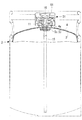
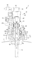
図1には、本実施形態に係る継手を備えた容器の縦断面概略構成図である。図2には、継手を構成しているプラグの縦断面概略構成図が示されている。図3から図6には、プラグとソケットとを接続する前の状態から接続を完了するまでを段階的に示した縦断面概略構成図が示されている。図7には、液出しチューブの先端形状が示されている。
[First Embodiment]
Hereinafter, a first embodiment of the present onset Ming will be described with reference to FIGS.
FIG. 1 is a schematic longitudinal sectional view of a container provided with a joint according to this embodiment. FIG. 2 shows a schematic configuration diagram of a longitudinal section of a plug constituting the joint. FIG. 3 to FIG. 6 show schematic longitudinal cross-sectional configuration diagrams showing in stages from the state before connecting the plug and the socket to the completion of the connection. FIG. 7 shows the tip shape of the liquid discharge tube.
継手(連結装置)は、液体と気体とが収容される容器2の外側容器用口部(口部)4aに設けられている。ここで、図1の継手として、プラグ11と、第2実施形態で説明する蓋61との構成が示されているが、本実施形態では、蓋61の代わりに後述するソケット(嵌合部材)41が設けられる点で異なる。
The joint (coupling device) is provided in the outer container mouth portion (mouth portion) 4a of the
本実施形態の継手1は、図3から図6に示すように、プラグ11とプラグ11と嵌合しているソケット41とを備えている。プラグ11とソケット41とは、固定ナット21を介して容器2の外側容器用口部(口部)4aに接続されている。
As shown in FIGS. 3 to 6, the joint 1 according to the present embodiment includes a
図1に示すように、容器2は、可撓性のライナー(可撓性容器)3と外側容器4とを備えている。ライナー3は、不活性材料で形成される可撓性フィルムの袋体と、比較的硬質の合成樹脂からなるライナーブラケット5とから構成される。可撓性フィルムの袋体の端部には、ライナーブラケット5が溶着されている。ライナー3は、予め洗浄されており外側容器4に収容されている。ライナー3から液体を排出した後には、ライナーブラケット5と共にライナー3を廃棄して、新たなライナーブラケット5と共にライナー3が外側容器4内に収容される。
As shown in FIG. 1, the
外側容器4は、アルミニウム製の缶である。外側容器4は、ライナーブラケット5を外側容器用口部4aにより支持して、ライナー3を外側容器4内に収容している。外側容器用口部4aの外壁には、雄ねじが形成されている。外側容器4は、繰返し使用されて毎回新しいライナー3が収容される複式格納型の容器となっている。
The
図2(A)に示すように、ライナーブラケット5には、ライナーブラケット用フランジ部5aが形成されており、外側容器用口部4aの内壁には、段差が設けられている。ライナーブラケット用フランジ部5aが外側容器用口部4aの内壁に設けられている段差に係止することにより、ライナーブラケット5が外側容器用口部4aに支持されることとなる。
As shown in FIG. 2 (A), the liner
ライナー3(図1参照)が外側容器4内に収容されてライナーブラケット5が外側容器用口部4aに支持された後、ライナー3は、好ましくは窒素または圧縮空気によって膨張される。ライナー3が膨張された後、ライナー3内には、後述する液体流路16および液出しチューブ15から液体が注入される。
After the liner 3 (see FIG. 1) is housed in the
図2(A)に示すように、ライナーブラケット5は、略円筒状とされている。略円筒状のライナーブラケット5は、その外壁の軸方向の略中央部が窪んでいる。ライナーブラケット5は、略中央部の窪みによって上方側が上部ライナーブラケット5bであり、下方側が下部ライナーブラケット5cとされている。下部ライナーブラケット5cには、図1に示すように、可撓性フィルムの袋体の端部が溶着されている。
As shown in FIG. 2A, the
上部ライナーブラケット5bは、その上面の縁部にライナーブラケット用フランジ部5aが形成されている。上部ライナーブラケット5bは、その外径が外側容器用口部4aの内径よりも僅かに小さいものとされている。ライナーブラケット用フランジ部5aは、上部ライナーブラケット5bの上面から上方に僅かに隆起して設けられている。そのため、ライナーブラケット用フランジ部5aによって後述するプラグ用フランジ部11cが支持されることにより、上部ライナーブラケット5bの上面とプラグ用フランジ部11cの下面との間には、間隙S1が形成されることとなる。
The
略円筒状の上部ライナーブラケット5bの開口部の内壁には、段差が形成されている。開口部の内壁に形成されている段差には、プラグ用円筒部11aの下方部が挿入される。また、上部ライナーブラケット5bには、開口部の円周に略等間隔にライナーブラケット用流体流路5dが複数設けられている。各ライナーブラケット用流体流路5dは、上部ライナーブラケット5bの軸方向に複数(例えば、4個所)設けられており、上部ライナーブラケット5bを貫通している。各ライナーブラケット用流体流路5dは、外側容器4とライナー3(図1参照)との間の内部空間に連通している。
A step is formed on the inner wall of the opening of the substantially cylindrical
プラグ11は、ライナー3内の液体に連通してライナー3内の液体を供出入する液体流路16と、ライナー3内の気体に連通してライナー3内の気体を供出入する気体流路17と、を有している円筒状のプラグ用円筒部11aと、気体流路17に連通してプラグ用円筒部11aの外壁に開口している開口部11bと、を備えている。
The
プラグ用円筒部11aは、外側容器4とライナー3との間に連通して外側容器4とライナー3との間の流体が供出入する流体流路19と、流体流路19の封止を解除する流体流路封止解除手段11fと、を有している。
The
プラグ用円筒部11aは、略円筒状のプラグ用円筒部11aの軸方向の略中央から半径方向に突出しているプラグ用フランジ部11cを有している。プラグ用円筒部11aは、その円筒状の頂面110(図2(A)においてプラグ用円筒部11aの上方の面)を有している。また、頂面110とプラグ用円筒部11aの外壁とによって形成されている角部(流体流路封止解除手段)11fは、面取りされている。面取りされた角部11fは、緩く曲面を形成している。
The
プラグ用円筒部11aは、プラグ用フランジ部11cを介してライナーブラケット用フランジ部5aによって下方から支持されている。これにより、プラグ11は、外側容器用口部4aに保持されることとなる。プラグ用フランジ部11cとライナーブラケット用フランジ部5aとの間には、オーリング101が担持されている。これにより、外側容器用口部4aが密封されることとなる。
The
プラグ用円筒部11aには、その円筒状の底面からライナー3(図1参照)の底部に向かって突出しているプラグ用突出部11dが設けられている。プラグ用円筒部11aおよびプラグ用突出部11dの中心部には、それらの軸方向に液体流路16が貫通している。
The
プラグ用フランジ部11cより下方のプラグ用円筒部11aは、上部ライナーブラケット5bの開口部に挿入されている。上部ライナーブラケット5bの開口部に挿入されたプラグ用円筒部11aは、開口部の内壁に設けられている段差に係止する。プラグ用円筒部11aの外壁と上部ライナーブラケット5bの開口部の内壁との間には、オーリング102が担持されている。このオーリング102が、プラグ用円筒部11aの下方部の外壁に密着することにより、ライナー3内の気体を封止することが可能となっている。
The
上部ライナーブラケット5bの開口部の上方からプラグ用突出部11dが挿入されることによって、プラグ用突出部11dと下部ライナーブラケット5cの開口部の内壁との間には、環状の環状流路18が形成される。この環状流路18は、プラグ用円筒部11aに設けられている気体流路17に連通している。これによって、ライナー3内の気体は、環状流路18から気体流路17を通って供出されることとなる。
By inserting the
プラグ用突出部11dの延在端には、液出しチューブ15が溶着されている。液出しチューブ15は、図1に示すように、下部ライナーブラケット5cの開口部からライナー3内の底部近傍まで延在している。ライナー3内の液体は、液出しチューブ15から液体流路16を通って供出されることとなる。この際に、液出しチューブ15は、可撓性のライナー3の残液が残らないように、外側容器4に接触しない範囲内でできるだけ長くすることが望ましい。
A
また、液出しチューブ15の先端形状としては、図7に示すように、先端に接しないようにその側壁に円孤の孔15aが複数設けられている。このように、側壁に円孤の孔15aを複数設けることによって、薬液(液体)供出用の有効面積が広くなるため、ライナー3が収縮した際に、孔15aが塞がれずに薬液を供出することができる。したがって、ライナー3内の残液を少なくすることができる。
As shown in FIG. 7, the
液出しチューブ15の先端を液出しチューブ15の軸方向に直交するように切りっぱなしにした場合には(図7において液出しチューブ15の先端を真横に切りっぱなしにした場合)、可撓性のライナー3が収縮した際には、液出しチューブ15の先端が塞がれてしまうことがあったりする。また、液出しチューブ15の先端をその軸方向に対して斜めにカットした場合には、有効面積を広くすることが可能となるが、可撓性のライナー3を破ってしまう恐れがある。しかし、図7に示すように、液出しチューブ15の先端に円孤の孔15aを設けることによって、可撓性のライナー3が液出しチューブ15によって破られることがなくなり、かつ、ライナー3内の残液をできるだけ少なくすることが実現可能となる。
When the tip of the
図2に示すように、プラグ用円筒部11aには、液体流路16の円周に複数(例えば4個所)の気体流路17が設けられている。複数設けられている気体流路17は、図2(B)に示すように、プラグ11のA−A部を上方から見たときに、液体流路16の円周に略等間隔に所定の角度(例えば、略90°の間隔)をもって配置されている。各気体流路17は、プラグ用円筒部11aの下端部の底面から頂面110の近傍まで液体流路16と略平行になるようにプラグ用円筒部11aを貫通している。各気体流路17は、プラグ用円筒部11aの頂面110の近傍においてプラグ用円筒部11aの外壁に開口している開口部11bに連通している。これにより、ライナー3(図1参照)内の気体と大気とを実質的に連通することができる。
As shown in FIG. 2, a plurality of (for example, four)
さらに、プラグ用円筒部11aには、液体流路16の円周に複数(例えば4個所)の流体流路19が設けられている。複数設けられている流体流路19は、図2(C)に示すように、プラグ11を上方から見たときに、液体流路16の円周に略等間隔に所定の角度(例えば、略90°の間隔)をもって配置されている。
Further, a plurality of (for example, four)
流体流路19と気体流路17とは、液体流路16の円周に同心円状に設けられている。流体流路19は、気体流路17の略外側に設けられており、流体流路19を2つの気体流路17が挟むように設けられている。
The
各流体流路19は、プラグ用円筒部11aの底面近傍から頂面110まで液体流路16と略平行になるようにプラグ用円筒部11aを貫通している。ここで、プラグ用円筒部11aの底面近傍とは、図2(A)に示すように、プラグ用フランジ部11cの下面近傍とされている。
Each
図2(A)に示すように、プラグ11がライナーブラケット5に下方から支持されることによって、プラグ用フランジ部11cの下面と上部ライナーブラケット5bの上面との間には、所定の間隙S1が設けられる。この間隙S1を介して、各流体流路19は、外側容器4とライナー3(図1参照)との間の内部空間と実質的に連通する。
As shown in FIG. 2A, when the
図3に示すように、継手1を構成しているソケット41は、プラグ用円筒部11aの外壁をプラグ用円筒部11aの軸方向に摺動する円筒状のソケット本体(ソケット用円筒部)42と、ソケット本体42に設けられて、プラグ用円筒部11aの開口部11bを封止するオーリング(開口部封止手段)105と、ソケット本体42に設けられて、プラグ用円筒部11aの液体流路16を封止するバルブ機構(液体流路封止手段)V1と、ソケット本体42に設けられて、プラグ用円筒部11aの流体流路19の封止を解除するコック(流体流路封止解除手段)57と、有している。
As shown in FIG. 3, the
本実施形態の継手1は、図1に示した蓋61を取り除いてソケット41を接続することにより、ライナー3内の液体を分配できるものである。
ソケット本体42は、円筒状とされている。円筒状のソケット本体42の下方側の外壁は、上方側の外壁の外径よりも小さくなっている。そのため、ソケット本体42の外径が異なる部分には、段差が設けられていることとなる。ソケット本体42は、その下端部の内壁面にオーリング105を担持している。
The
The
オーリング105は、2本設けられている。オーリング105a、105bは、プラグ用円筒部11aの外壁に密着して開口部11bへの気体の供出入を防止している。オーリング105a、105bは、ソケット41とプラグ11との接続が完了した際に、開口部11bを挟むことができるような間隔を有して設けられている。
Two O-
ソケット本体42の内部には、バルブ機構V1が設けられている。ソケット本体42の内部に設けられているバルブ機構V1は、略円筒状とされている。略円筒状のバルブ機構V1は、その内壁によって形成されているバルブ機構用液体流路45と、バルブ機構用液体流路45内に配置されている弁体46と、インナースリーブ47と、バルブ機構用圧縮コイルばね48と、連結座49と、を備えている。
Inside the
インナースリーブ47は、その内部にバルブ機構用液体流路45の一部が形成されており、胴部47aには、伸縮自在なベローズが形成されている。インナースリーブ47の外壁には、複数のスリット47bが形成されている。スリット47bは、インナースリーブ47の軸方向にインナースリーブ47の上端面の近傍まで貫通している。スリット47bの下端側は、プラグ用円筒部11aに設けられている流体流路19に連通しており、他端側は、ソケット41とプラグ11との接続が完了することによって供入出ポートP1に接続される。
The
インナースリーブ47の下端側には、弁体46が有している弁46aが当接するシート部47c(図6参照)が設けられている。弁体46は、バルブ機構用液体流路45内に配置されている。弁体46は、その先端側に弁46aを有している。バルブ機構用圧縮コイルばね48は、インナースリーブ47がその軸方向に伸長するように力を付勢するものである。連結座49は、インナースリーブ47のシート部47c側に結合されている。連結座49は、プラグ用円筒部11aの頂面110に付勢されて密着する。
On the lower end side of the
また、インナースリーブ47の下端側の面(プラグ用円筒部11aの頂面110と接する面)には、オーリング106が設けられている。オーリング106は、インナースリーブ47の内部に形成されているバルブ機構用流体流路45の外周に設けられている。このように、オーリング106がバルブ機構用流体流路45の外周に設けられることによって、ソケット41とプラグ11とが接合した際にバルブ機構用流体流路45から液体が流出したり、バルブ機構用流体流路45に気体が流入することを防止している。
Further, an O-
インナースリーブ47の外径は、インナースリーブ47に対応しているソケット本体42の内径よりも僅かに小さいものとされている。インナースリーブ47の上端面側には、後述する排出ポート部材49が設けられている。排出ポート部材49がインナースリーブ47の上端面側に設けられることにより、インナースリーブ47は、ソケット本体42の内部に固定されることとなる。
The outer diameter of the
排出ポート部材49は、略円筒状とされており、その内壁がインナースリーブ47に形成されているバルブ機構用液体流路45に連通している。インナースリーブ47と接している反対側の面には、排出ポート部材49の内壁から導かれた液体の排出ポートP2が形成されている。
The
ソケット本体42は、バルブ機構V1によって、プラグ用円筒部11aの頂面110に付勢されて密着する。ソケット本体42がプラグ用円筒部11aの頂面110に付勢されて密着することによって、プラグ用円筒部11aの液体流路16およびバルブ機構V1に設けられているバルブ機構用液体流路45を介してライナー3(図1参照)から分配された液体を供出入可能となっている。
The
ソケット本体42の下方の外壁には、スリーブ43が保持されている。スリーブ43は、略円筒状とされている。スリーブ43の内壁には、内側に向かって突出している段差が設けられている。スリーブ43は、その外壁に所定の形状に窪んでいる複数のスリット(窪み部)43aを有している。各スリット43aは、スリーブ43の軸方向に複数設けられている。各スリット43aは、固定ナット21の内壁に設けられているキーリング(突出部)58に係合可能な形状とされている。
A
スリーブ43は、プラグ用円筒部11aを覆うように着脱自在に係止可能なロック機構2rをスリーブ43の内壁の段差に有している。ロック機構2rは、複数のボール50と、ボールリテーナ51と、スライドリング52と、有している。ロック機構2rは、施錠子としてボール50が用いられている、いわゆるボールキャッチである。
The
スライドリング52は、略円筒状をしている。略円筒状のスライドリング52は、ソケット本体42とスリーブ43との間に配置されている。スライドリング52は、複数のボール50をスリーブ43の下端側に付勢することにより、複数のボール50が縮径する方向に押圧している。プラグ用円筒部11aの外壁には、複数のボール50が係止される環状の係止溝11gが設けられているのでプラグ11にソケット41が着脱自在に接続される。
The
ボールリテーナ51は、ソケット本体42の一部により構成されている。ボールリテーナ51とスリーブ43との間には、複数のボール50が保持されている。ボールリテーナ51とスリーブ43とは、ボールリテーナ51とスリーブ43とが離間しないように略円筒状のクリップリング54によって相互に結合されている。
The
複数のボール50は、スリーブ43の下端側の内壁に配置されている。複数のボール50は、ボールリテーナ51によって保持されている。ボールリテーナ51は、複数のボール50が軸方向に移動する動きおよびボールリテーナ51の外壁方向に拡縮する動きのみを許容する複数の嵌合穴51aを有している。
The plurality of
スリーブ43の内壁の段差には、スライドリング52と共にロック機構用圧縮コイルばね53が収容されている。ロック機構用圧縮コイルばね53は、スリーブ43の内壁に設けられている段差にスライドリング52を付勢するものである。スリーブ43の内壁に設けられている段差に収容されているロック機構用圧縮コイルばね53およびスライドリング52は、ソケット本体42とスリーブ43の内壁とによって周囲されている。
A locking mechanism
ソケット本体42の上方の外壁には、ソケット本体42からプラグ11を経て外側容器4とライナー3(図1参照)との間の内部空間に外圧(流体)を供給(供入)するライナー加圧用接続部56が設けられている。ライナー加圧用接続部56は、ソケット本体42内に形成されている供入出ポートP1に連通している。
The outer wall above the
また、ソケット本体42の上方の外壁には、外側容器4とライナー3との間の内部空間に封止された外圧を排出するコック57が設けられている。コック57を回動させることによって、供入出ポートP1に連通して供入出ポートP1内の外圧を排出(供出)することができるようになっている。外側容器4とライナー3との間の内部空間に外圧を供給する場合には、コック57を回動することによって供入出ポートP1内の外圧の排出(供出)を封止する。
Further, a
固定ナット21は、プラグ11とソケット41とを容器2の外側容器用口部4aに接続している。ソケット41を接続する場合には、固定ナット21の内壁にキーリング58が設けられる。キーリング58は、ソケット本体42の下方の外壁を支持しているスリーブ43の外壁に形成されている各スリット43aに係合可能な形状とされている。キーリング58は、リング状の誤接防止手段である。キーリング58と各スリット43aとの形状は、所定の形状とされているため、複数種のソケット41がある場合であっても、ソケット41とプラグ11との取り付け間違いを防止することができる。
The fixing
次に、ソケット41を取り付ける流れについて、図3から図6を用いて説明する。
図3には、ソケット41がプラグ11と分離している状態を示し、図4には、プラグ11の上部にソケット41を搭載した状態が示されている。
Next, the flow of attaching the
FIG. 3 shows a state in which the
外側容器用口部4aに接続されているプラグ11にソケット41を搭載する。この際、ソケット41に設けられているロック機構2rの複数のボール50は、それらの一部が各嵌合穴51aから突出した状態となっている。
The
図5には、プラグ11にソケット41を挿入した状態が示されている。
プラグ11に対してソケット41を挿入することによって、ソケット本体42に内蔵されているバルブ機構V1がプラグ用円筒部11aの頂面110に付勢される。バルブ機構V1がプラグ用円筒部11aの頂面110に付勢されることによって、ソケット本体42の下端面とプラグ用円筒部11aの頂面110とが密着する。この際、バルブ機構V1の弁46aは、インナースリーブ47に設けられているシート部47c(図6参照)に当接しており、バルブ機構V1内部のバルブ機構用液体流路45が遮断されていることとなる。
FIG. 5 shows a state in which the
By inserting the
また、ボールリテーナ51の端部がプラグ用円筒部11aの頂面110に付勢される。そのため、ソケット41に設けられているロック機構2rの複数のボール50が各嵌合穴51a(図4参照)に案内されて後退する。また、複数のボール50の後退運動に連動して、スライドリング52も後退する。スライドリング52が一定距離後退すると、スライドリング52が退避した空間に複数のボール50が移動する。すなわち、複数のボール50は、拡径する方向に移動し、複数のボール50の一部が各嵌合穴51aから退避する。
Further, the end of the
図6には、プラグ11にソケット41を更に挿入して、プラグ11とソケット41との接続を完了した状態が示されている。
プラグ11に対してソケット41を更に挿入することによって、ソケット本体42に設けられているバルブ機構V1のシート部47cから弁46aが離反する。そのため、バルブ機構V1内部のバルブ機構用液体流路45が流通可能となる。また、後述するようにスリーブ43がプラグ用円筒部11aに係止された状態となるので、液出しチューブ15、液体通路16とバルブ機構V1のバルブ機構用液体流路45とが直結し、ライナー3(図1参照)から分配された液体を受け入れることが可能となる。
FIG. 6 shows a state in which the
By further inserting the
前述したように、ソケット41に設けられているロック機構2rの複数のボール50がプラグ用円筒部11aに設けられている環状の係止溝11g(図3参照)に到達する。そのため、スライドリング52が付勢されてボール50がプラグ用円筒部11aに設けられている係止溝11gに嵌合してロック状態となる。
As described above, the plurality of
次に、ソケット41からライナー3内の液体を供出する際の流体、気体、液体の流れについて、図6を用いて説明する。
ソケット本体42に設けられているライナー加圧用接続部56から外圧(流体)を供給する。外圧は、ライナー加圧用接続部56からソケット本体42内に形成されている供入出ポートP1へと導かれる。ソケット41のプラグ11への挿入が完了しているため、供入出ポートP1は、インナースリーブ47の外壁に形成されている複数のスリット47bへと導かれる。
Next, the flow of fluid, gas, and liquid when the liquid in the
External pressure (fluid) is supplied from a liner pressurizing
複数のスリット47bに導かれた外圧は、プラグ用円筒部11aの頂面110からプラグ用円筒部11aに設けられている流体流路19へと導かれる。ここで、インナースリーブ47の下端側の面には、オーリング106が設けられているため、インナースリーブ47の下端側の面とプラグ用円筒部11aの頂面110とが密着されている。また、ソケット本体42の開口側の先端に設けられている2本のオーリング105a、105bがソケット本体42の開口側の先端とプラグ用円筒部11aの側壁とを密着している。そのため、スリット47bから導かれた外圧は、オーリング106と上方側のオーリング105aとによって、密封されたまま流体流路19へと導かれることとなる。
The external pressure guided to the plurality of
流体流路19に導かれた外圧は、上部ライナーブラケット5bの上面とプラグ用フランジ部11cの下面との間に形成されている間隙S1へと導かれる。間隙S1に導かれた外圧は、上部ライナーブラケット5bに設けられているライナーブラケット用流体流路5dから外側容器4とライナー3(図1参照)との間の内部空間へと導かれる。
The external pressure guided to the
ライナー3には、内部空間に導かれた外圧が作用する。そのため、ライナー3内の液体が液出しチューブ15、液体流路16へと導かれる。液体流路16に導かれた液体は、ソケット本体42に設けられているシート部47cから弁46aが離反しているため、バルブ機構V1内部に形成されているバルブ機構用液体流路45へと導かれる。バルブ機構用液体流路45に導かれた液体は、バルブ機構用液体流路45と連通している排出ポート部材49に設けられている排出ポートP2から供出される。
An external pressure guided to the internal space acts on the
次に、プラグ11からソケット41を取り外す際の流体、気体、液体の流れについて、図5および図6を用いて説明する。
図6において、ライナー加圧用接続部56から供給される外圧を停止する。ソケット本体42に設けられているコック57を回動させて、供入出ポートP1内の外圧を排出(供出)する。これによって、インナースリーブ47のスリット47b内の圧力、プラグ用円筒部11aの流体流路19内の圧力と外側容器4とライナー3(図1参照)との間の内部空間内の圧力とが直ちに大気圧と一致する。
Next, the flow of fluid, gas, and liquid when removing the
In FIG. 6, the external pressure supplied from the liner pressurizing
図5に示すように、プラグ11からソケット41を引き抜こうとする(取り外す)ことによって、ソケット本体42の開口側の先端がプラグ用円筒部11aの外壁をプラグ用円筒部11aの軸方向に頂面110に近づくように摺動する。ソケット本体42の開口側の先端に設けられている下方側のオーリング105bがプラグ用円筒部11aの外壁をプラグ用円筒部11aの軸方向に摺動して開口部11bを通過することによって、開口部11bの封止が解除される。
As shown in FIG. 5, when the
開口部11bの封止が解除されるため、ライナー3内の上部に収容されていた気体が下部ライナーブラケット5cの内壁とプラグ用突出部11dとの間に形成されている環状流路18から気体流路17を経て開口部11bへと導かれて排出(供出)される。開口部11bから排出された気体は、ボールリテーナ51とプラグ用円筒部11aの外壁およびボールリテーナ51とスリーブ43との間を経て、スリーブ43の外壁とキーリング58と間を通過して外気へと排出される。
Since the
ソケット41を複数のボール50が係止溝11g(図3参照)を乗り越える強い力によってスリーブ11から引き抜く。これにより、スリーブ11からソケット41を分離することができる。スリーブ11からソケット41を分離することによって、ライナー3内の圧力と、液出しチューブ15および液体流路16の圧力が大気圧となる。そのため、プラグ11からソケット41を取り外す際に、ライナー3内から液出しチューブ15を経て液体流路16へと液体が導かれて外側容器用口部4a外へと液体が排出されて飛散することを防止できる。
The
また、インナースリーブ47の下端側の面とプラグ用円筒部11aの頂面110との間に設けられているオーリング106によって、ライナー3内から液出しチューブ15を経て液体流路16へと液体が導かれて外側容器用口部4a外へと液体が排出されて飛散することを更に防止できる。
Further, the O-
以上の通り、本実施形態に係る継手1によれば、以下の作用効果を奏する。
気体流路17、流体流路19、液体流路16を備えているプラグ11を用いることとした。そのため、液体流路16、気体流路17、流体流路19を形成する部品を減らすことができる。したがって、継手(連結装置)1の組立工程の簡略化やコストダウンをはかることできる。
また、摺動する部品を用いることなく液体流路16、気体流路17、流体流路19を有しているプラグ11にすることができるので、部品が摺動する際に生じる微粉(パーティクル)の発生を防止することができる。
As mentioned above, according to the joint 1 which concerns on this embodiment, there exist the following effects.
The
Further, since the
円筒状のプラグ用円筒部11aの軸方向に同心円状になるように所定の角度をもって気体流路17と流体流路19とを設けることとした、そのため、プラグ用円筒部11aといった簡易な部材だけで気体流路17と流体流路19とを形成することができる。したがって、継手1の組立工程の簡略化やコストダウンをはかることできる。
The
プラグ11の液体流路16を封止するバルブ機構(液体流路封止手段)V1と、流体流路19の封止を解除するコック(流体流路封止解除手段)57と、を備えているソケット(嵌合部材)41を用いて、ソケット41をプラグ用円筒部11aの軸方向に摺動させて開口部11dの封止を解除すると共に、流体流路19の封止をコック57を回動させることによって解除した後に、バルブ機構V1が液体流路16の封止を解除することとした。そのため、ライナー(可撓性容器)3内に収容されている気体と液体とが一緒に容器2から供出されることを防止することができる。したがって、容器2から液体を供出する際に液体が飛散することを防止することができる。
A valve mechanism (liquid flow path sealing means) V1 for sealing the
嵌合部材であるソケット41は、プラグ用円筒部11aの外壁をプラグ用円筒部11aの軸方向に摺動する円筒状のソケット本体(ソケット用円筒部)42と、ソケット本体42に設けられてプラグ用円筒部11aの開口部11bを封止しているオーリング(開口部封止手段)105と、ソケット本体42に設けられて、プラグ用円筒部11aの液体流路16を封止しているバルブ機構V1と、ソケット本体42に設けられて、流体流路19の封止を解除するコック(流体流路封止解除手段)57と、備えることとした。このソケット41を取り外す際には、開口部11bの封止を解除するととも、コック57によって流体流路19の封止を解除してからソケット41を取り外すこととした。そのため、ライナー3に作用する外圧(流体)が開放された後に、開口部11bの封止が解除されて液体流路16の封止が解除されることとなる。したがって、気体と液体とが一緒にライナー3から供出されることを防止して、ソケット41をプラグ11から取り外す際に液体が飛散することを防止することができる。
The
ソケット本体42に設けられているスリーブ43の外壁に所定の形状に窪んでいるスリット(窪み部)43aを設けて、ソケット41が挿入されている円筒状の固定ナット(接続手段)21の内壁側には、その半径方向にスリーブ43のスリット43aに係合可能なキーリング(突出部)58を設けることとした。そのため、固定ナット21にソケット41を挿入する際に、固定ナット21のキーリング58の形状とスリーブ43のスリット43aの形状とが異なっている場合には、ソケット41を取り付けることができない。したがって、複数種のソケット41がある場合であっても、ソケット41とプラグ11との取り付け間違いを防止することができる。
An inner wall side of a cylindrical fixing nut (connecting means) 21 into which a
[第2実施形態]
本実施形態の継手は、プラグと蓋とを備えている点で、第1実施形態と相違し、その他は同様である。したがって、同一の構成については、同一の符号を付してその説明を省略する。
以下、本発明の第2実施形態について、図1および図8から図10を用いて説明する。
継手31は、図1および図8から図10に示すように、プラグ11とプラグ11と嵌合している蓋(嵌合部材)61とを備えている。
[Second Embodiment]
The joint of this embodiment is different from the first embodiment in that it includes a plug and a lid, and the others are the same. Therefore, about the same structure, the same code | symbol is attached | subjected and the description is abbreviate | omitted.
Hereinafter, a second embodiment of the present invention will be described with reference to FIGS. 1 and 8 to 10.
As shown in FIGS. 1 and 8 to 10, the joint 31 includes a
蓋61は、プラグ用円筒部11aの外壁をプラグ用円筒部11aの軸方向に摺動する円筒状のプラグガイド(封止用円筒部)63と、プラグガイド63に設けられて、プラグ用円筒部11aの開口部11bを封止するオーリング(開口部封止手段)107と、プラグガイド63に設けられて、プラグ用円筒部11aの液体流路16を封止するプラグブッシュ部(液体流路封止手段)63bと、を有している。
The
蓋61は、防塵蓋であり、金属製である。蓋61の内壁には、固定ナット(接続手段)21に螺合する雌ねじが設けられており、蓋61は、外側容器用口部(口部)4aから離反するように固定ナット21に対して移動可能となっている。固定ナット21は、プラグ11と蓋61とを容器2の外側容器用口部4aに接続している。
The
蓋61を締めたときには、プラグガイド63の内底面がプラグ用円筒部11aの頂面110に当接するようになっている。プラグブッシュ部63bおよびプラグガイド63は、ライナー(可撓性容器)3に収容されている薬品(液体)に触れる可能性が高いため耐食性を有する合成樹脂からなることが好ましい。
When the
プラグガイド63は、その軸方向の断面形状がコの字形状とされている。コの字形状のプラグガイド63は、その開口側が蓋61の内部に突出している。プラグガイド63の開口側に対して反対側の面(蓋61に当接する面)には、プラグガイド用フランジ部63aが形成されている。プラグガイド用フランジ部63aは、ボルト(図示せず)によって、蓋61の内側から円盤状の押さえ板65を介して蓋61に固定されている。
The
プラグガイド63の開口側は、その先端の内壁面にオーリング107を担持している。オーリング107は、プラグ用円筒部11aの外壁に密着して開口部11bからの気体の流出を防止している。
The opening side of the plug guide 63 carries an O-
プラグガイド63の開口側の中央部には、プラグブッシュ部63bが設けられている。すなわち、プラグブッシュ部63bは、プラグガイド63の開口側の面の略中央部から下方に向かって突出している突出部である。プラグブッシュ部63bは、略円柱状とされている。
A
プラグブッシュ部63bの先端部は、プラグ用円筒部11aの頂面110に開口している液体通路16に挿入されている。液体通路16に挿入されているプラグブッシュ部63bの先端部は、液体通路16の内径より僅かに小さいものとされている。プラグブッシュ部63bは、その先端部の外壁面にオーリング108を担持している。オーリング108は、液体通路16の内壁に密着して液体通路16からの液体の流出を防止している。
The distal end portion of the
次に、蓋61を取り外す際の流体、気体、液体の流れについて、図8から図10を用いて説明する。
図8には、輸送状態等であって蓋61を締めた場合が示されている。
外側容器4とライナー3との間の内部空間には、蓋61を締めた際の外気(流体)が封止されている。また、ライナー3内の上部には、輸送中に液体から発生した気体が貯留しており、その下部には、液体が収容されている。
Next, the flow of fluid, gas, and liquid when removing the
FIG. 8 shows a case where the
Outside air (fluid) when the
蓋61が締められているため、蓋61に一体化して設けられているプラグガイド63の内底面がプラグ用円筒部11aの頂面110に当接し、プラグブッシュ部63bの先端部がプラグ用円筒部11aの液体流路16に挿入されている。プラグガイド63の開口側の先端は、プラグ用円筒部11aの外壁に開口している開口部11bを覆う位置とされている。そのため、プラグガイド63の開口側の先端に設けられているオーリング107によって、開口部11bへの外気の通気および開口部11bからの内気(ライナー3内の気体)の通気が封止されている。
Since the
プラグブッシュ部63bの先端部に設けられているオーリング108によってプラグ用円筒部11aの液体流路16を形成している内壁との間が封止されている。そのため、液体流路16への外気の通気および液体流路16からの液体の供出が封止されている。
以上の様に、外側容器用口部4aからの液体の供出と共に、外側容器4とライナー3との間の内部空間の外気(流体)およびライナー3内の気体の供出が封止されていることとなる。
The O-
As described above, the supply of liquid from the
次に、蓋61が半開状態の場合について説明する。図9には、蓋61が半開状態にされた場合が示されている。
蓋61を半開状態に緩める場合には、蓋61が外側容器用口部4aから離反するように固定ナット21に対して移動される。蓋61が外側容器用口部4aから離反するように移動することによって、蓋61に一体化して設けられているプラグガイド63の開口側の先端がプラグ用円筒部11aの外壁をプラグ用円筒部11aの軸方向にプラグ用円筒部11aの頂面110に近づくよう(図9において上方)に摺動する。これによって、プラグガイド63の内底面がプラグ用円筒部11aの頂面110から離反する。
Next, a case where the
When the
また、プラグガイド63に設けられているプラグブッシュ部63bの先端部がプラグ用円筒部11aの頂面110に近づくようにプラグ11の流体流路16の内壁を軸方向(図9において上方)に摺動する。
Further, the inner wall of the
プラグガイド63の開口側の先端に設けられているオーリング107がプラグ用円筒部11aの外壁をプラグ用円筒部11aの軸方向に摺動して開口部11bを通過することによって、蓋61は半開状態とされる。
When the O-
プラグガイド63の開口側の先端に設けられているオーリング107が開口部11bを通過することによって、開口部11bの封止が解除される。開口部11bの封止が解除されるため、ライナー3内の上部に収容されていた気体が下部ライナーブラケット5cの内壁とプラグ用突出部11dとの間に形成されている環状流路18から気体流路17を経て開口部11bへと導かれて排出(供出)される。開口部11bから排出された気体は、蓋61と蓋61に螺合している固定ナット21との間の隙間から外気へと排出される。
The O-
次に、蓋61を取外す寸前の状態について説明する。図10には、蓋61を取外す寸前の場合が示されている。
蓋61を取外すためには、図9から更に蓋61を外側容器用口部4aから離反するように固定ナット21に対して移動させる。蓋61が外側容器用口部4aから更に離反するように移動することによって、蓋61に一体化して設けられているプラグガイド63の開口側の先端がプラグ用円筒部11aの外壁をプラグ用円筒部11aの軸方向に頂面110に更に近づくように摺動する。プラグガイド63の内底面がプラグ用円筒部11aの頂面110から更に離反する。
Next, the state just before removing the
In order to remove the
プラグ用円筒部11aの角部11fは、面取りされて緩く曲面を形成しているためプラグガイド63の開口側の先端が角部11fまで摺動することによって、プラグガイド63の開口側の先端に設けられているオーリング107の封止が解除される。
Since the
オーリング107の封止が解除されるため、プラグガイド63の開口側の先端とプラグ用円筒部11aの外壁との間が大気圧とされる。これにより、プラグガイド63の内底面とプラグ用円筒部11aの頂面110との間の間隙S2も大気圧とされるため、外側容器4とライナー3との間の内部空間に封止されていた外気が、ライナーブラケット用流体流路5dから間隙S1を経て流体流路19へと導かれる。流体流路19に導かれた外気は、プラグ用円筒部11aの頂面110から排出される。
Since the sealing of the O-
プラグ用円筒部11aの頂面110に開口している流体流路19から排出された外気は、プラグガイド63の開口側の先端とプラグ用円筒部11aの角部11fとの間を通過して、蓋61と蓋61に螺合している固定ナット21との間の隙間をから外気へと排出される。
The outside air discharged from the
外気が排出された後に、蓋61を固定ナット21から取り外す。蓋61には、プラグブッシュ部63bが一体化して設けられているため、蓋61を取り外すことによって、プラグブッシュ部63bの先端部がプラグ用円筒部11aの液体流路16から取り除かれることとなる。
After the outside air is discharged, the
以上の様に、蓋61の螺合を緩めることによって、気体流路17の圧力とライナー3内との圧力が直ちに大気圧と一致する。さらに、蓋61を取り除く寸前には、外側容器4とライナー3との間の外気の圧力が直ちに大気圧と一致する。この際に、すでにライナー3内の圧力が大気圧となっているので、ライナー3内から液出しチューブ15を経て液体流路16へと液体が導かれて外側容器用口部4a外へと供出されて飛散することを防止できる。
As described above, by loosening the screwing of the
以上の通り、本実施形態に係る継手31によれば、以下の作用効果を奏する。
蓋(嵌合部材)61は、プラグ用円筒部11aの外壁をプラグ用円筒部11aの軸方向に摺動する円筒状のプラグガイド(封止用円筒部)63と、プラグガイド63の開口側の先端に設けられているオーリング(開口部封止手段)107と、プラグガイド63と共に蓋61に一体化して設けられているプラグブッシュ部(液体流路封止手段)63bと、を備えることとした。また、容器2の外側容器用口部(口部)4aには、プラグ11と蓋61とを外側容器用口部4aに接続している固定ナット(接続手段)21を設けて、蓋61を外側容器用口部4aから離反するように固定ナット21に対して移動することができることとした。これにより、蓋61を外側容器用口部4aから離反するように固定ナット21に対して移動させることにより、プラグガイド63をプラグ用円筒部11aの軸方向に摺動させることができる。そのため、プラグ用円筒部11aの開口部11bの封止を解除した後に、液体流路16の封止を解除することができる。したがって、ライナー(可撓性容器)3から気体と液体が一緒に供出されることを防止して、ライナー3から液体を供出する際に液体が飛散することを防止することができる。
As described above, according to the joint 31 according to the present embodiment, the following operational effects can be obtained.
The lid (fitting member) 61 includes a cylindrical plug guide (sealing cylinder) 63 that slides on the outer wall of the
1 継手(連結装置)
2 容器
3 ライナー(可撓性容器)
4a 外側容器用口部(口部)
11 プラグ
16 液体流路
17 気体流路
19 流体流路
1 Joint (coupling device)
2
4a Outer container mouth (mouth)
11
Claims (5)
前記プラグは、
円筒状のプラグ用円筒部と、
前記液体に連通して該液体を供出入する液体流路と、
前記気体に連通して該気体を供出入する気体流路と、
前記容器と前記可撓性容器との間に連通して流体が供出入する流体流路と、を備え、
前記気体流路と、前記流体流路とは、前記プラグ用円筒部の軸方向に同心円状に各々所定の角度を有して複数設けられることを特徴とする連結装置。 A coupling device provided at a mouth portion of a container including a flexible container for containing liquid and gas therein, and including a plug and a fitting member that is fitted to the plug. ,
The plug is
A cylindrical portion for a cylindrical plug;
A liquid flow path that communicates with the liquid and delivers the liquid;
A gas flow path communicating with the gas and delivering the gas;
A fluid flow path through which fluid is communicated between the container and the flexible container ;
And the gas flow path, wherein the fluid flow path, each coupling device for a plurality provided wherein isosamples a predetermined angle concentrically in the axial direction of the plug cylinder.
前記嵌合部材は、前記流体流路の封止を解除する流体流路封止解除手段と、前記液体流路を封止する液体流路封止手段と、を備え、
前記プラグ用円筒部の外壁を軸方向に摺動して前記開口部の封止を解除するとともに、前記流体流路封止解除手段によって前記流体流路の封止が解除された後に、前記液体流路の封止を解除する摺動部を有することを特徴とする請求項1に記載の連結装置。 The plug includes an opening communicating with the gas flow path and opening in an outer wall of the plug cylinder.
The fitting member includes a fluid channel sealing release unit that releases the sealing of the fluid channel, and a liquid channel sealing unit that seals the liquid channel,
With releasing the sealing of the opening by sliding the outer wall of the pre-Symbol plug cylinder in the axial direction, after the sealing of the fluid flow path is released by the fluid flow path unsealing means, said The coupling device according to claim 1, further comprising a sliding portion that releases the sealing of the liquid flow path.
前記容器の口部には、前記プラグと前記ソケットとを前記容器の口部に接続する接続手段を設けて、
前記ソケットを取り外す際には、前記開口部の封止を解除するとともに、前記流体流路封止解除手段によって前記流体流路の封止が解除された後に取り外すことを特徴とする請求項2に記載の連結装置。 The fitting member is provided in a cylindrical socket cylindrical portion that slides on an outer wall of the plug cylindrical portion in the axial direction of the plug cylindrical portion, and the socket cylindrical portion, and seals the opening. An opening sealing means for stopping, a liquid flow path sealing means for sealing the liquid flow path provided in the socket cylindrical part, and a liquid flow path sealing means for sealing the liquid flow path. A fluid channel seal release means for releasing the seal,
In the mouth portion of the container, connecting means for connecting the plug and the socket to the mouth portion of the container is provided,
When removing the socket is configured to release the sealing of the opening, to claim 2, characterized in that removal after sealing of the fluid flow path is released by the fluid flow path unsealing means The coupling device as described.
該ソケット用円筒部は、その外壁に所定の形状に窪んでいる窪み部を有し、
前記接続手段は、その内壁の半径方向に前記窪み部に係合可能な突出部を有することを特徴とする請求項3に記載の連結装置。 The connecting means has a cylindrical shape, and the cylindrical portion for the socket is inserted on the inner wall side of the connecting means,
The socket cylindrical portion has a recessed portion that is recessed in a predetermined shape on its outer wall,
The connecting device according to claim 3, wherein the connecting means has a protrusion that can engage with the recess in a radial direction of an inner wall thereof.
前記容器の口部には、前記プラグと前記蓋とを前記容器の口部に接続する接続手段を設け、
前記蓋は、前記容器の口部から離反するように前記接続手段に対して移動可能であることを特徴とする請求項2に記載の連結装置。 The fitting member is provided in a cylindrical sealing cylindrical portion that slides on an outer wall of the plug cylindrical portion in an axial direction of the plug cylindrical portion, and the opening cylindrical portion. An opening sealing means for sealing the liquid flow path sealing means provided in the sealing cylindrical portion and sealing the liquid flow path,
The mouth of the container is provided with connection means for connecting the plug and the lid to the mouth of the container,
The coupling device according to claim 2 , wherein the lid is movable with respect to the connection means so as to be separated from the mouth of the container.
Priority Applications (5)
| Application Number | Priority Date | Filing Date | Title |
|---|---|---|---|
| JP2010180224A JP4713676B1 (en) | 2010-08-11 | 2010-08-11 | Connecting device |
| TW100122516A TW201202100A (en) | 2010-08-11 | 2011-06-27 | Coupling device |
| KR1020110066417A KR101100378B1 (en) | 2010-08-11 | 2011-07-05 | Coupling device |
| CN2011102046129A CN102424217A (en) | 2010-08-11 | 2011-07-13 | Coupling device |
| US13/208,320 US8590566B2 (en) | 2010-08-11 | 2011-08-11 | Coupling device |
Applications Claiming Priority (1)
| Application Number | Priority Date | Filing Date | Title |
|---|---|---|---|
| JP2010180224A JP4713676B1 (en) | 2010-08-11 | 2010-08-11 | Connecting device |
Publications (2)
| Publication Number | Publication Date |
|---|---|
| JP4713676B1 true JP4713676B1 (en) | 2011-06-29 |
| JP2012035900A JP2012035900A (en) | 2012-02-23 |
Family
ID=44292663
Family Applications (1)
| Application Number | Title | Priority Date | Filing Date |
|---|---|---|---|
| JP2010180224A Active JP4713676B1 (en) | 2010-08-11 | 2010-08-11 | Connecting device |
Country Status (5)
| Country | Link |
|---|---|
| US (1) | US8590566B2 (en) |
| JP (1) | JP4713676B1 (en) |
| KR (1) | KR101100378B1 (en) |
| CN (1) | CN102424217A (en) |
| TW (1) | TW201202100A (en) |
Cited By (3)
| Publication number | Priority date | Publication date | Assignee | Title |
|---|---|---|---|---|
| JP2013071778A (en) * | 2011-09-29 | 2013-04-22 | Surpass Kogyo Kk | Connector for liquid tank |
| JP2013095474A (en) * | 2011-10-31 | 2013-05-20 | Surpass Kogyo Kk | Liquid storage container |
| KR20200129214A (en) * | 2019-05-07 | 2020-11-18 | 이덕재 | Oxygen tank collector for fuel cell system of submarine |
Families Citing this family (9)
| Publication number | Priority date | Publication date | Assignee | Title |
|---|---|---|---|---|
| USD713931S1 (en) | 2013-01-09 | 2014-09-23 | Central Garden & Pet Company | Sprayer |
| US9868584B2 (en) | 2013-10-24 | 2018-01-16 | Dai Nippon Printing Co., Ltd. | Chemical storage container and method for replacing its internal atmosphere with dry air |
| JP6388818B2 (en) | 2014-10-31 | 2018-09-12 | サーパス工業株式会社 | Plug integrated container |
| WO2016133200A1 (en) * | 2015-02-20 | 2016-08-25 | セメダイン株式会社 | Long flow path member, plastic container, and viscous-liquid discharge device |
| JP6837760B2 (en) | 2016-06-23 | 2021-03-03 | サーパス工業株式会社 | connector |
| JP6679429B2 (en) * | 2016-06-23 | 2020-04-15 | サーパス工業株式会社 | Connectors and sockets |
| JP6650179B2 (en) | 2016-06-23 | 2020-02-19 | サーパス工業株式会社 | Connectors and sockets |
| KR20180044749A (en) * | 2016-10-24 | 2018-05-03 | 삼성전자주식회사 | Fluid dispenser |
| JP7490194B2 (en) * | 2020-05-29 | 2024-05-27 | アサヒビール株式会社 | Replacement parts for beverage containers |
Citations (5)
| Publication number | Priority date | Publication date | Assignee | Title |
|---|---|---|---|---|
| JP2001192099A (en) * | 1999-10-26 | 2001-07-17 | Surpass Kogyo Kk | Connecting device |
| JP2002114242A (en) * | 2000-10-11 | 2002-04-16 | Surpass Kogyo Kk | Container and plug therefor |
| JP2005132465A (en) * | 2003-10-31 | 2005-05-26 | Surpass Kogyo Kk | Connector for liquid supply from tank |
| WO2005119115A1 (en) * | 2004-06-01 | 2005-12-15 | Surpass Industry Co., Ltd. | Connector to be attached to liquid tank and liquid tank provided with the connector |
| WO2008035628A1 (en) * | 2006-09-19 | 2008-03-27 | Surpass Industry Co., Ltd. | Connector for liquid tank |
Family Cites Families (3)
| Publication number | Priority date | Publication date | Assignee | Title |
|---|---|---|---|---|
| US5335821A (en) * | 1992-09-11 | 1994-08-09 | Now Technologies, Inc. | Liquid chemical container and dispensing system |
| JP4474160B2 (en) * | 2001-07-12 | 2010-06-02 | インテグリス・インコーポレーテッド | Dispensing head, dispensing system including dispensing head, and liquid recirculation method using dispensing head |
| JP3914560B1 (en) * | 2006-01-31 | 2007-05-16 | 東京応化工業株式会社 | Fittings for fluid containers |
-
2010
- 2010-08-11 JP JP2010180224A patent/JP4713676B1/en active Active
-
2011
- 2011-06-27 TW TW100122516A patent/TW201202100A/en unknown
- 2011-07-05 KR KR1020110066417A patent/KR101100378B1/en active IP Right Grant
- 2011-07-13 CN CN2011102046129A patent/CN102424217A/en active Pending
- 2011-08-11 US US13/208,320 patent/US8590566B2/en active Active
Patent Citations (5)
| Publication number | Priority date | Publication date | Assignee | Title |
|---|---|---|---|---|
| JP2001192099A (en) * | 1999-10-26 | 2001-07-17 | Surpass Kogyo Kk | Connecting device |
| JP2002114242A (en) * | 2000-10-11 | 2002-04-16 | Surpass Kogyo Kk | Container and plug therefor |
| JP2005132465A (en) * | 2003-10-31 | 2005-05-26 | Surpass Kogyo Kk | Connector for liquid supply from tank |
| WO2005119115A1 (en) * | 2004-06-01 | 2005-12-15 | Surpass Industry Co., Ltd. | Connector to be attached to liquid tank and liquid tank provided with the connector |
| WO2008035628A1 (en) * | 2006-09-19 | 2008-03-27 | Surpass Industry Co., Ltd. | Connector for liquid tank |
Cited By (5)
| Publication number | Priority date | Publication date | Assignee | Title |
|---|---|---|---|---|
| JP2013071778A (en) * | 2011-09-29 | 2013-04-22 | Surpass Kogyo Kk | Connector for liquid tank |
| US9126713B2 (en) | 2011-09-29 | 2015-09-08 | Surpass Industry Co., Ltd. | Liquid-tank connector |
| JP2013095474A (en) * | 2011-10-31 | 2013-05-20 | Surpass Kogyo Kk | Liquid storage container |
| KR20200129214A (en) * | 2019-05-07 | 2020-11-18 | 이덕재 | Oxygen tank collector for fuel cell system of submarine |
| KR102186614B1 (en) * | 2019-05-07 | 2020-12-04 | 이덕재 | Oxygen tank collector for fuel cell system of submarine |
Also Published As
| Publication number | Publication date |
|---|---|
| TW201202100A (en) | 2012-01-16 |
| KR101100378B1 (en) | 2011-12-30 |
| CN102424217A (en) | 2012-04-25 |
| US8590566B2 (en) | 2013-11-26 |
| JP2012035900A (en) | 2012-02-23 |
| US20120037625A1 (en) | 2012-02-16 |
| TWI361785B (en) | 2012-04-11 |
Similar Documents
| Publication | Publication Date | Title |
|---|---|---|
| JP4713676B1 (en) | Connecting device | |
| KR100955979B1 (en) | Joint for fluid container | |
| JP3914559B1 (en) | Fluid container | |
| JP4717996B2 (en) | Container and plug used therefor | |
| US6568427B2 (en) | Connector for fluid container | |
| US8870037B2 (en) | Plug structure | |
| JP5395865B2 (en) | Punk repair kit | |
| TWI423918B (en) | Connector for liquid tank | |
| JP4306857B2 (en) | Containment system | |
| JP2018080745A (en) | Filling device | |
| US9404622B2 (en) | Filling port structure for pressure fluid | |
| JPH0539898A (en) | Cylinder valve with pressure reducing valve | |
| CN109237295B (en) | Filling device | |
| US9157459B2 (en) | Liquid storage container | |
| JP2009056681A (en) | Tire puncture repair apparatus | |
| JP2005510428A (en) | Container discharge system with grounding device | |
| JP2011189559A (en) | Sealing pumping up device | |
| KR101438507B1 (en) | Pressure vessel for storing chemical | |
| CN111684198A (en) | Filling device | |
| JP2001124297A (en) | Gass discharge preventing device also used for filling gas |
Legal Events
| Date | Code | Title | Description |
|---|---|---|---|
| TRDD | Decision of grant or rejection written | ||
| A01 | Written decision to grant a patent or to grant a registration (utility model) |
Free format text: JAPANESE INTERMEDIATE CODE: A01 Effective date: 20110315 |
|
| A61 | First payment of annual fees (during grant procedure) |
Free format text: JAPANESE INTERMEDIATE CODE: A61 Effective date: 20110324 |
|
| R150 | Certificate of patent or registration of utility model |
Ref document number: 4713676 Country of ref document: JP Free format text: JAPANESE INTERMEDIATE CODE: R150 |
|
| R250 | Receipt of annual fees |
Free format text: JAPANESE INTERMEDIATE CODE: R250 |
|
| R250 | Receipt of annual fees |
Free format text: JAPANESE INTERMEDIATE CODE: R250 |
|
| R250 | Receipt of annual fees |
Free format text: JAPANESE INTERMEDIATE CODE: R250 |
|
| R250 | Receipt of annual fees |
Free format text: JAPANESE INTERMEDIATE CODE: R250 |
|
| R250 | Receipt of annual fees |
Free format text: JAPANESE INTERMEDIATE CODE: R250 |
|
| R250 | Receipt of annual fees |
Free format text: JAPANESE INTERMEDIATE CODE: R250 |