US20030192737A1 - Outlet silencer and heat recovery structures for gas turbine - Google Patents
Outlet silencer and heat recovery structures for gas turbine Download PDFInfo
- Publication number
- US20030192737A1 US20030192737A1 US10/122,479 US12247902A US2003192737A1 US 20030192737 A1 US20030192737 A1 US 20030192737A1 US 12247902 A US12247902 A US 12247902A US 2003192737 A1 US2003192737 A1 US 2003192737A1
- Authority
- US
- United States
- Prior art keywords
- housing
- sound attenuating
- airflow
- duct
- air
- Prior art date
- Legal status (The legal status is an assumption and is not a legal conclusion. Google has not performed a legal analysis and makes no representation as to the accuracy of the status listed.)
- Granted
Links
Images


Classifications
-
- F—MECHANICAL ENGINEERING; LIGHTING; HEATING; WEAPONS; BLASTING
- F28—HEAT EXCHANGE IN GENERAL
- F28F—DETAILS OF HEAT-EXCHANGE AND HEAT-TRANSFER APPARATUS, OF GENERAL APPLICATION
- F28F9/00—Casings; Header boxes; Auxiliary supports for elements; Auxiliary members within casings
- F28F9/02—Header boxes; End plates
- F28F9/026—Header boxes; End plates with static flow control means, e.g. with means for uniformly distributing heat exchange media into conduits
- F28F9/0263—Header boxes; End plates with static flow control means, e.g. with means for uniformly distributing heat exchange media into conduits by varying the geometry or cross-section of header box
-
- F—MECHANICAL ENGINEERING; LIGHTING; HEATING; WEAPONS; BLASTING
- F02—COMBUSTION ENGINES; HOT-GAS OR COMBUSTION-PRODUCT ENGINE PLANTS
- F02C—GAS-TURBINE PLANTS; AIR INTAKES FOR JET-PROPULSION PLANTS; CONTROLLING FUEL SUPPLY IN AIR-BREATHING JET-PROPULSION PLANTS
- F02C7/00—Features, components parts, details or accessories, not provided for in, or of interest apart form groups F02C1/00 - F02C6/00; Air intakes for jet-propulsion plants
- F02C7/08—Heating air supply before combustion, e.g. by exhaust gases
-
- F—MECHANICAL ENGINEERING; LIGHTING; HEATING; WEAPONS; BLASTING
- F01—MACHINES OR ENGINES IN GENERAL; ENGINE PLANTS IN GENERAL; STEAM ENGINES
- F01D—NON-POSITIVE DISPLACEMENT MACHINES OR ENGINES, e.g. STEAM TURBINES
- F01D25/00—Component parts, details, or accessories, not provided for in, or of interest apart from, other groups
- F01D25/30—Exhaust heads, chambers, or the like
-
- F—MECHANICAL ENGINEERING; LIGHTING; HEATING; WEAPONS; BLASTING
- F22—STEAM GENERATION
- F22B—METHODS OF STEAM GENERATION; STEAM BOILERS
- F22B1/00—Methods of steam generation characterised by form of heating method
- F22B1/02—Methods of steam generation characterised by form of heating method by exploitation of the heat content of hot heat carriers
- F22B1/18—Methods of steam generation characterised by form of heating method by exploitation of the heat content of hot heat carriers the heat carrier being a hot gas, e.g. waste gas such as exhaust gas of internal-combustion engines
- F22B1/1807—Methods of steam generation characterised by form of heating method by exploitation of the heat content of hot heat carriers the heat carrier being a hot gas, e.g. waste gas such as exhaust gas of internal-combustion engines using the exhaust gases of combustion engines
- F22B1/1815—Methods of steam generation characterised by form of heating method by exploitation of the heat content of hot heat carriers the heat carrier being a hot gas, e.g. waste gas such as exhaust gas of internal-combustion engines using the exhaust gases of combustion engines using the exhaust gases of gas-turbines
-
- F—MECHANICAL ENGINEERING; LIGHTING; HEATING; WEAPONS; BLASTING
- F01—MACHINES OR ENGINES IN GENERAL; ENGINE PLANTS IN GENERAL; STEAM ENGINES
- F01N—GAS-FLOW SILENCERS OR EXHAUST APPARATUS FOR MACHINES OR ENGINES IN GENERAL; GAS-FLOW SILENCERS OR EXHAUST APPARATUS FOR INTERNAL-COMBUSTION ENGINES
- F01N1/00—Silencing apparatus characterised by method of silencing
- F01N1/24—Silencing apparatus characterised by method of silencing by using sound-absorbing materials
-
- F—MECHANICAL ENGINEERING; LIGHTING; HEATING; WEAPONS; BLASTING
- F01—MACHINES OR ENGINES IN GENERAL; ENGINE PLANTS IN GENERAL; STEAM ENGINES
- F01N—GAS-FLOW SILENCERS OR EXHAUST APPARATUS FOR MACHINES OR ENGINES IN GENERAL; GAS-FLOW SILENCERS OR EXHAUST APPARATUS FOR INTERNAL-COMBUSTION ENGINES
- F01N2310/00—Selection of sound absorbing or insulating material
- F01N2310/02—Mineral wool, e.g. glass wool, rock wool, asbestos or the like
-
- F—MECHANICAL ENGINEERING; LIGHTING; HEATING; WEAPONS; BLASTING
- F01—MACHINES OR ENGINES IN GENERAL; ENGINE PLANTS IN GENERAL; STEAM ENGINES
- F01N—GAS-FLOW SILENCERS OR EXHAUST APPARATUS FOR MACHINES OR ENGINES IN GENERAL; GAS-FLOW SILENCERS OR EXHAUST APPARATUS FOR INTERNAL-COMBUSTION ENGINES
- F01N5/00—Exhaust or silencing apparatus combined or associated with devices profiting by exhaust energy
- F01N5/02—Exhaust or silencing apparatus combined or associated with devices profiting by exhaust energy the devices using heat
Definitions
- This invention relates to duct units and other devices that can be connected to an air flow outlet of a machine having a rotating axial flow member, for example, a gas turbine and the invention further includes heat recovery apparatus.
- a damper can then be provided, which damper in a first position can direct the hot air flow upwardly through a suitable outlet stack (also referred to as a by-pass stack) which can, in some cases, include some form of silencer arranged in a duct section in order to reduce the level of sound exiting from the stack.
- a suitable outlet stack also referred to as a by-pass stack
- the hot air can be directed through another pipe section to a heat recovery system, ie. a heat recovery steam generator.
- the known heat recovery steam generators can be quite tall and they can include an exterior housing in which is mounted an array of heat exchanging units. Each heat exchanging unit can comprise a series of heat exchanging pipes through which a liquid such as water flows. The flowing water is heated by the hot exhaust gases from the turbine resulting in the generation of steam.
- the known hot gas outlet arrangements designed for attachment to the outlet of a gas turbine of the aforementioned type suffer from several disadvantages and deficiencies.
- the known outlet stack arrangements even if they are provided with some form of duct silencer, are not very efficient at reducing the level of sound exiting from the gas turbine.
- the silencer module if it is provided at all, may be spaced a substantial distance from the outlet of the gas turbine and, due to its location, the silencer duct is not particularly efficient in terms of sound reduction due to the transmission of sound through the walls of the ducts located upstream of the silencer.
- a silencer duct located along the path for the by-pass stack will be useless in reducing the amount of noise generated by the turbine and exiting from the hot air outlet system.
- a further substantial difficulty with the known heat recovery apparatus used downstream from a gas turbine is that the hot air from the turbine is not directed evenly over the heat exchanging units which may be mounted in series in a tower-like housing. If the hot air is distributed unevenly, then this will result in uneven heating of the heat exchanging fluid flowing through the heat exchanging units, reducing the efficiency of the heat recovery for the steam generator. Also, uneven hot air distribution in the heat recovery apparatus can result in excessive pressure loss in this apparatus, reducing the gas turbine efficiency.
- It is a further object of the present invention to provide a heat recovery apparatus which includes a housing containing an array of heat exchanging units and a series of aerodynamic diffusers adjacent an inlet of the housing, the diffusers acting to redirect a substantial portion of incoming hot air in order that this hot air will pass more uniformly through the heat exchanging units.
- a sound attenuating duct unit suitable for connection to an airflow outlet of a machine having a rotating axial flow member includes a duct housing having exterior sides and two opposite ends. An air inlet is located in one of these ends and the housing further includes first and second air outlets with the first air outlet located at the other end of the housing. The air inlet is adapted for connection to the airflow outlet of the machine. Interior walls are arranged in the housing and define a main airflow passageway system which extends from the air inlet to both of the first and second outlets. Sound absorbing material is arranged between the interior walls and the exterior sides of the duct housing and sound attenuating members are mounted in the airflow passageway system.
- a diverter damper is mounted in the duct housing and is movable between a first position where the damper directs airflow entering through the air inlet to the first air outlet and a second position where the damper directs the air flow to the second air outlet.
- the sound attenuating members are mounted between the diverter damper and the air inlet so as to reduce the sound levels emitted through either of the air outlets during use of the duct unit.
- the sound attenuating members comprise a series of splitters rigidly mounted in the airflow passageway system and dividing the main air flow passageway system into smaller passageways.
- a sound attenuating duct unit suitable for connection to an outlet of a stationary gas turbine includes a duct housing having exterior sides, an air inlet in one end of the housing that lies in a first plane, and first and second air outlets with the first air outlet located in one of the exterior sides of the housing spaced from said one end and the second air outlet located in another of the exterior sides that extends in a second plane arranged at a substantial angle to the first plane.
- the air inlet is adapted for connection to the outlet of a gas turbine in order to receive hot air flow from the turbine.
- Interior walls are arranged in the housing and define side walls of a main airflow passageway that extends from the air inlet to both of the first and second outlets.
- Sound absorbing material is arranged between the interior walls and the exterior sides of the housing.
- a series of sound absorbing splitters are rigidly mounted in the air flow passageway and extend transversely from one side of the main airflow passageway to an opposite side thereof. The splitters divide the main air flow passageway into smaller passageways and contain sound attenuating material capable of withstanding high air flow temperatures of gas turbine exhaust air.
- a diverter damper is mounted in the duct housing and is movable between a first position where the damper directs the hot air flow to the first air outlet and a second position where the damper directs this hot air flow to the second air outlet.
- the series of splitters are mounted between the diverter damper and the air inlet so that the hot air flow exiting from the smaller air passageways flows to a selected one of the first and second air outlets.
- this duct unit includes a central air flow defining member rigidly mounted in the housing and extending inwardly from the air inlet to the series of splitters.
- a heat recovery apparatus includes a housing having exterior walls, a hot airflow inlet and an airflow outlet.
- An array of hot exchanging units is mounted in this housing, each heat exchanging unit being adapted for heat exchange between a hot air flow and a heat exchanging liquid flowing through pipes of the heat exchanging unit.
- a series of aerodynamic diffusers are mounted in the housing adjacent the air flow inlet. The aerodynamic diffusers redirect at least a substantial portion of hot air flow entering the housing through the air flow inlet during use of the apparatus in order that the hot air flow passes more uniformly through the heat exchanging units.
- the aerodynamic diffusers extend horizontally and are arranged one above another.
- FIG. 1 is a schematic elevation of a known system for generating power by means of a large gas turbine mounted horizontally in a protective structure, the illustrated system including a pair of outlet stacks and a heat recovery steam generator;
- FIG. 2 is a side elevation of a sound attenuating duct unit constructed in accordance with the invention, this view also illustrating a section of a by-pass stack;
- FIG. 3 is a horizontal cross-section taken along the line III-III of FIG. 2, this view showing splitters arranged in the duct section;
- FIG. 4 is a velocity profile illustrating the advantage of turning vanes in a heat recovery apparatus such as a heat recovery steam generator, this view illustrating the uniform low velocity air passing through the region where heat exchanging units would be located;
- FIG. 5 is a vertical cross-section of an aerodynamic diffuser or turning vane that can be used in the heat recovery apparatus of the invention
- FIG. 6 is a vertical cross-section of another form of aerodynamic diffuser that can be used in the heat recovery apparatus
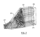
- FIG. 7 is a schematic illustration of airflow patterns common in a prior art heat recovery apparatus.
- FIG. 8 is a schematic side elevation of a typical heat recovery steam generator which can use the aerodynamic diffusers of FIG. 5 or FIG. 6, this view being partly in vertical cross-section in the regions of the heat exchanging units in order to illustrate same.
- FIG. 1 Illustrated in FIG. 1 is a schematic view of an electrical power generating system employing a large, stationary gas turbine 10 .
- the gas turbine can be of standard construction and it can be protected by means of a building or structure 12 .
- the turbine can be rigidly mounted on a thick concrete pad 14 .
- Intake air for the turbine is drawn in through an air intake filter arrangement 16 which can be mounted on a suitable support frame 18 .
- a gas turbine generator 20 Arranged below the filter arrangement 16 is a gas turbine generator 20 which can be fitted with a suitable generator circuit breaker.
- a circular hot air outlet for the turbine is located at 22 .
- Connected downstream of the turbine outlet is a bypass stack 24 through which the hot exhaust gases from the turbine can be passed, if required or appropriate.
- this stack can contain a duct silencer located in duct section 26 which has an enlarged horizontal cross-section.
- a by-pass stack module 28 which is open on its right side (as seen in FIG. 1) for inflow of the hot exhaust gases from the turbine.
- a diverter damper of known construction which can be moved from a first position wherein the damper forces the air flow to pass upwardly through the bypass stack to a second position where the damper allows the hot exhaust gases to flow into a heat recovery steam generator 30 .
- the heat recovery section contains an array of heat exchanging units in which a fluid such as water flows for purposes of heat exchange with the hot exhaust gases from the gas turbine.
- an exhaust gas stack 32 of known construction is through this stack that exhaust air of reduced temperature eventually exits to atmosphere after passing through the heat recovery steam generator.
- the bypass stack 24 is shown supported by a steel supporting framework 34 that extends upwardly from the ground.
- FIG. 2 illustrates an improved sound attenuating duct unit 40 constructed in accordance with the invention which can be used in place of the prior art airflow outlet arrangement illustrated in FIG. 1, that is, in place of the known duct structure that is connected to the outlet of the gas turbine, including the bypass stack module 28 .
- the duct unit 40 is suitable for connection to an airflow outlet of not only a gas turbine but other machines having a rotating fan or axial flow member that generates a significant amount of noise.
- the duct unit 40 includes a duct housing 42 having exterior sides and two opposite ends including an end 44 wherein an air inlet indicated at 46 is provided.
- the exterior sides of the housing can be constructed of suitable metal plates such as mild steel or stainless steel plates.
- the illustrated exterior sides include a horizontal top 48 , a bottom 50 and two vertically extending side walls 52 and 54 (see FIG. 3). There is also a sloping wall 56 that is connected along its lower edge to the top 48 and there is a vertical side wall 58 located opposite the wall 56 .
- an expansion joint 60 which per se can be of known construction.
- the duct unit of the invention can include a bypass stack section 62 , the upper portion of which is not shown in FIG. 2 for ease of illustration.
- the upper end of this stack terminates in an air outlet 64 where the hot air flow from the gas turbine can exit to atmosphere.
- the upper portion of the by-pass stack section 62 is preferably of circular cross-section and, if it is, there can be a transition section 67 whose horizontal cross-section changes from rectangular (or square) to circular.
- the bypass stack can include a wider section (of rectangular, horizontal cross-section) provided for sound attenuation. In the embodiment of FIG. 2, this wider section is indicated at 66 and it can include a plurality of splitter members 68 which individually can be of known construction.
- splitter members can extend from one inner side wall of the section 66 to the opposite inner side wall and they divide the main airflow passageway into a series of smaller, parallel passageways 70 which can be as few as four (or less) as shown.
- these splitters are preferably made with perforated sheet metal panels 72 , 74 .
- These splitter members are preferably filled with sound attenuating material that is able to withstand the high temperatures of the hot air flow passing through the section 66 .
- An optional feature of the splitter members 68 is a layer of stainless steel screen 79 , 81 which is arranged behind the perforated sheet metal, this screen helping to prevent the escape of the sound attenuating material through the holes in the perforated sheet metal.
- the splitters 68 are located only in the wider section 66 and they preferably do not extend into the transition section 67 . This is indicated by the curved ends indicated at 73 in dash lines.
- the illustrated duct unit of FIG. 2 also has another air outlet located generally at 80 .
- the outlet 80 can be considered as located at the other or second end of the duct housing, that is the end opposite the aforementioned end 44 .
- the air outlet 64 sometimes herein referred to as the second air outlet, can be considered as located in a plane indicated at B which, in the illustrated duct unit of FIG. 2, extends horizontally.
- the aforementioned air inlet 46 lies in a first plane indicated by the dash line A in FIG. 2 and it will be seen that the plane B lies at a substantial angle to the first plane A. As illustrated, this substantial angle is 90 degrees.
- the duct unit 40 of the invention also has interior walls arranged in the duct housing 42 and it is these interior walls which define main airflow passageway system 82 , a system which extends from the air inlet 46 to both of the first and second outlets.
- the interior walls shown in FIG. 2 include upper and lower transition wall sections 84 , 86 , flat upper wall 88 and lower interior wall 90 .
- the wall 90 extends from transition wall 86 to the first air outlet 80 while upper wall 88 extends from the transition wall 84 to an arc-shaped interior wall section 92 which curves upwardly to the duct section 66 .
- a planar interior wall section 94 extends upwardly at a small acute angle to a vertical plane from a diverter damper 96 to the vertically extending duct section 66 .
- All of these interior walls are preferably made of perforated stainless steel sheet metal of suitable composition and of sufficient thickness (gauge) to withstand high temperature air flows. It is also possible to construct these interior walls of solid sheet metal (imperforate metal).
- At least the attenuator section 66 can also be constructed with perforated interior walls indicated at 100 and 102 . It will be appreciated that these perforated interior walls can be on all four sides of the attenuator section 66 . If desired, the perforated interior walls can extend upwardly along the upper portion of the bypass stack as indicated at 104 and 106 in FIG. 2.
- FIG. 3 illustrates additional, vertically extending interior walls 108 , 110 which can also be perforated and made of stainless steel.
- the interior walls 108 , 110 extend through a duct transition section 112 .
- These interior walls 108 , 110 could also be made of solid (imperforate) sheet metal, if desired. It will be understood that in this section, the length of which is indicated as L in FIG. 3, the transverse cross-section of the main airflow passageway 82 changes from circular to square or rectangular.
- this transition section there is preferably located a central airflow defining member 115 which is rigidly mounted in the duct transition section 112 and which extends inwardly from the air inlet at 46 .
- This airflow defining member has a central longitudinal axis indicated at X which extends through the centre of the air inlet 46 .
- the exterior of this central airflow defining member is made with strong, perforated sheet metal suitable for high temperature conditions, such as stainless steel.
- This sheet metal exterior 116 preferably forms a truncated cone as shown in FIG. 3 with the member tapering inwardly in the direction of the hot air flow.
- this air flow defining member 115 is filled with sound attenuating material which must be capable of withstanding the hot temperatures of the air flow rushing past its sheet metal exterior.
- the sound attenuating material must be capable of withstanding airflow temperatures of gas turbine exhaust air, which can be higher than 500° C.
- the preferred sound attenuating material is ceramic fiber or mineral wool.
- the sheet metal should have a thickness of at least 12 gauge. By using this thicker gauge, the perforated sheet metal will not bend and distort when its temperature becomes elevated and subjected to stresses and other forces acting thereon. This applies to all interior surface materials used where high temperatures may be created.
- the metal components in the duct unit that are exposed to the hot air stream should be constructed so as to allow for quick expansion when exposed to high temperature gradients within a few seconds of turbine start up.
- a short, connecting flange 118 used to connect the end 44 of the duct unit to the expansion joint 60 at the outlet of the gas turbine.
- An optional feature of the airflow defining member is the use of a layer 137 of stainless steel screen arranged behind the perforated sheet metal to prevent the escape of the sound attenuating material through the holes in the perforated sheet metal.
- splitters 120 Located downstream of the airflow defining member 115 and close to or next to this member are a series of so-called splitters 120 which are sound attenuating members and which are rigidly mounted in the airflow passageway system. These splitters divide the main air flow passageway 82 into smaller passageways 122 . Each of these splitters also has an exterior formed of perforated sheet metal indicated at 124 and each splitter is filled with sound attenuating material 126 . In the preferred embodiment illustrated in FIG. 3, there are five evenly spaced splitters with the central splitter aligned with the central axis X of the airflow defining member 115 . It will be understood that each splitter extends from one interior side wall of the main airflow passageway 82 to the opposite interior side wall and, although the illustrated splitters extend vertically, it is also quite possible for the splitters to extend instead in a horizontal direction.
- each splitter 120 has a semi-cylindrical nose section 128 which can be made of imperforate metal.
- a tail section 130 of each splitter is tapered in the direction of the air flow and this section can be made of perforated metal.
- the splitters should also be constructed so that they are capable of withstanding high temperatures of gas turbine exhaust air which can be higher than 500° C.
- sound attenuating material filling each splitter is preferably heat resistant material such as mineral wool or ceramic fiber.
- the gauge of the sheet metal used to form the exterior of each splitter is preferably 12 gauge.
- splitters Again an optional feature of these splitters is the use of a layer of stainless steel screen 133 , 135 arranged directly behind the perforated sheet metal to prevent the escape of the sound attenuating material.
- a layer of stainless steel screen 133 , 135 arranged directly behind the perforated sheet metal to prevent the escape of the sound attenuating material.
- the use of the screens 133 , 135 is shown in only one of the splitters 120 but it will be understood that these layers can be used in all of these splitters.
- the sound attenuating members or splitters 120 are mounted between the diverter valve or damper 96 and the air inlet 46 . Due to the location of the sound attenuating members, they are capable of providing a substantial reduction of the sound levels emitted through either of the air outlets during use of this sound attenuating duct unit.
- silencer modules in the by-pass stack section and/or the main exhaust stack can be simplified by using a larger space between adjacent splitters or by even eliminating splitters. This reduces the pressure drop across the sound attenuating members in the exhaust system, reduces manufacturing costs, and reduces maintenance expenditures.
- the preferred form of the diverter damper 96 is illustrated schematically in FIG. 2.
- the preferred damper comprises a large, planar, rectangular or square metal flap constructed to withstand the hot air flow temperatures passing by the damper.
- the preferred metal for this purpose is stainless steel, for example, type 409 stainless steel.
- sheet metal forming the exterior of the damper can be reinforced or strengthened by suitable supporting frame members that are covered by the sheet metal.
- a detailed description of the construction of the pivoting damper itself herein is deemed unnecessary as dampers of this general type are known in this art.
- a diverter damper of this type is sold by Mannesmann Seiffert under the trademark ROUTEFLEX. This known diverter damper is pivoted about a horizontal axis by means of an internal toggle link lever drive connected to one side of the pivoting damper member.
- the damper 96 pivots about its upper or rear edge on a pivot shaft 140 , the ends of which are mounted in the sides of the duct unit.
- the actual mechanism for pivoting the large damper 96 is not shown, it will be appreciated that any suitable known mechanism for pivoting a large damper can be used provided it has sufficient strength and it does not interfere unduly with the hot air flow through the airflow passageway in either position of the damper.
- the illustrated damper 96 is movable between a first position indicated by dash lines at 142 in FIG. 2 where the damper directs airflow entering through the air inlet to the first air outlet 80 and a second position shown in solid lines at 144 where the damper directs the air flow to the second air outlet 64 . It will be seen from FIG.
- the diverter damper in the first position 142 extends substantially horizontally, permitting the hot airflow from the turbine to flow directly and without a significant change in direction to the outlet 80 where this air flow can pass into a heat recovery unit.
- the damper In the second position, the damper extends at a substantial acute angle indicated at 146 to a horizontal plane. Because of the slope of the damper or flap and because of the integration of sloping wall section 94 and the curved interior surface of wall section 92 , the damper is able to smoothly direct or turn the hot air flow in an upwards direction to permit this air flow to pass smoothly through the splitter members 68 and eventually through the outlet 64 .
- the slope of the damper and the slope of the wall sections provides a smoother flow and thus a lower pressure drop than conventional dampers.
- the invention also provides an improved heat recovery apparatus that can be used downstream of the aforementioned air outlet 80 . Except for the differences in construction noted herein, this heat recovery apparatus can be constructed in the same manner as the heat recovery steam generator 30 illustrated in FIG. 1.
- This apparatus includes a housing 150 (shown only schematically in FIG. 4) having exterior walls, a hot airflow inlet 152 and an airflow outlet such as the aforementioned exhaust gas stack 32 .
- the exterior walls of the housing can include horizontal bottom walls 154 , 156 , sloping top walls 158 , 160 and horizontal top wall 162 .
- this housing 150 contains an array of heat exchanging units (shown in FIG. 8) which are rigidly mounted therein. Each heat exchanging unit is adapted for heat exchange between the hot air flow that enters through the inlet 152 and a heat exchanging liquid, ie. water, flowing through pipes of the heat exchanging unit.
- a heat exchanging liquid ie. water
- aerodynamic diffusers 175 are mounted in the region of the airflow inlet 152 and they are preferably mounted one above the other as shown.
- the number of these diffusers can vary depending upon the size of the heat recovery apparatus and the particular requirements for airflow redirection. As illustrated, these diffusers can be located in a relatively short duct section 177 having a horizontal bottom wall and an upwardly sloping top wall 158 .
- these aerodynamic diffusers redirect at least a substantial portion of the hot air flow coming from the turbine and entering the housing through the inlet 152 during use of the heat recovery apparatus in order that the hot air flow passes more uniformly through the heat exchanging units.
- these aerodynamic diffusers 175 extend horizontally as shown and they extend from one side wall of the duct section to the opposite side wall.
- the diffusers 175 and their connections to the side walls are constructed in a manner known per se so as to allow for quick expansion when they are exposed to high temperature gradients within a few seconds of turbine startup.
- the duct section in which the diffusers are mounted can be considered a transition duct portion of the housing as it provides a transition from the lower outlet 80 of the above described sound attenuating duct unit to the relatively large, vertically extending housing that contains the heat exchanging units.
- At least a majority of the aerodynamic diffusers 175 are curved as shown in the drawings from their leading edges 182 (see FIG. 5) to the rear ends 180 with each diffuser forming a concave curve indicated at 184 on a top side thereof.
- the illustrated diffuser 175 also provides acoustical treatment or sound attenuation in order to reduce the level of sound passing through the heat recovery apparatus.
- the curved upper surface of the diffuser is made of perforated sheet metal stainless steel indicated at 186 .
- this diffuser has a double wall construction and the bottom surface of the diffuser can be made with solid stainless steel sheet metal indicated at 188 .
- Between the two curved walls is suitable sound attenuating material 190 which can fill the interior space of the diffuser.
- the preferred sound attenuating material is mineral wool because of its low cost and ability to withstand high temperatures.
- Other possible sound attenuating materials include ceramic fibers and silica fibers but these materials are more expensive.
- the leading end of the diffuser can have a semi-cylindrical shape as shown in FIGS. 5 and 6.
- Brace plates or connecting plates 192 , 194 can extend between the two curved walls forming the diffuser and these help to provide the correct spacing between the walls for good performance.
- a diffuser of the type illustrated in FIG. 6 can be used.
- This diffuser 200 does not contain any sound attenuating material and both the upper curved panel 202 and the lower curved panel 204 are made of solid stainless steel sheet metal. Except for these differences, this aerodynamic diffuser can be the same in its construction and in its mounting as the diffuser 175 .
- the present heat recovery apparatus has the advantage of low back pressure in the region of the air flow inlet 152 and the diffusers located a short distance downstream of this inlet.
- a low pressure drop is advantageous from an efficiency standpoint and it is achieved by reason of the good aerodynamic design.
- FIG. 7 illustrates the airflow pattern through the heat recovery steam generator if no aerodynamic diffusers or turning vanes are provided.
- the hot air flows reasonably smoothly and in one direction through the transition duct section 177 ′, the air flow in the much larger transition section 210 is quite turbulent and virtually is in all directions. This is due to the fact that the hot air flow is simply dumped into the much larger transition space or transition passageway formed by the transition section 210 .
- FIG. 4 illustrates what occurs when aerodynamic diffusers constructed in accordance with the invention are provided, it will be seen that the air flow through the large transition section 210 is more evenly distributed over the expanding height of this section and is much less turbulent. The result is a more uniform distribution of the hot air flow through the section 212 in which the heat exchanging units are located.
- the heat exchanging units in the section 212 are in the form of heat recovery steam generating coils through which water passes and is heated for steam creation.
- An additional advantage that is achieved through the use of the present aerodynamic diffusers and that arises from the more uniform air flow distribution across the heat exchanging units is the elimination or reduction of vibrations in the heat exchanging units or on the inside walls of the transition section 210 , which can otherwise be created. It will be appreciated that in the case where there is excessive hot air flow through the lower sections of the heat exchanging units, this air flow, which can be of a fairly high velocity, can create vibrations in the lower heat exchanging units.
- turbulent airflow can be generated inside the transition section 210 if the aerodynamic diffusers are not used. This type of airflow can produce induced vibration on the inner walls of the section 210 and can result in premature fatigue failure of the liner material and its support structure.
- FIG. 8 illustrates a typical known heat recovery steam generator in which the series of aerodynamic diffusers (described above) can be used.
- the steam generator includes a high pressure superheater 220 which comprises an array of heat exchanging units in the form of pipes through which water flows.
- the water which is a heat exchanging liquid, is heated by the hot gases to generate steam.
- a duct burner 222 and burner outlet duct 224 can be provided next to the superheater 220 on the downstream side.
- the hot gas flow then can pass through a high pressure evaporator 226 .
- Shown on top of the housing and directly above the evaporator 226 is a high pressure drum 228 while downstream of the evaporator and extending the height of the housing is a high pressure economizer 230 which also comprises heat exchanging units.
- a low pressure section of the steam generator can include a low pressure superheater 232 , a low pressure evaporator 234 and a low pressure drum 236 mounted on top of the housing. Mounted above the drum 236 is an integral deaerator. Arranged between the evaporator 234 and the stack is a feedwater heater 238 that extends the height of the housing as shown. Also illustrated in FIG. 8 is a selective catalytic reducter 240 located between the high pressure evaporator 226 and the high pressure economizer 230 . Although one form of heat recovery steam generator has been illustrated in FIG. 8, clearly other forms and other versions of such steam generators are well known in the steam generator art and the use of the present invention is not limited to the particular steam generator that has been illustrated.
Landscapes
- Engineering & Computer Science (AREA)
- Combustion & Propulsion (AREA)
- Chemical & Material Sciences (AREA)
- Mechanical Engineering (AREA)
- General Engineering & Computer Science (AREA)
- Physics & Mathematics (AREA)
- Thermal Sciences (AREA)
- Geometry (AREA)
- Life Sciences & Earth Sciences (AREA)
- Sustainable Development (AREA)
- Sustainable Energy (AREA)
- Heat-Exchange Devices With Radiators And Conduit Assemblies (AREA)
- Exhaust Silencers (AREA)
Abstract
Description
- This invention relates to duct units and other devices that can be connected to an air flow outlet of a machine having a rotating axial flow member, for example, a gas turbine and the invention further includes heat recovery apparatus.
- The use of large gas turbines for generating electrical power is well known in the power generation art. These large gas turbines can be mounted horizontally in a building or other shelter that provides protection to the turbine against the elements. The outlet for the turbine, through which passes a hot air flow at substantial speed, can be connected to a diffuser duct of cylindrical configuration and then to a transition duct which transforms the hot air outlet passageway from a circular cross-section to a rectangular cross-section. A damper can then be provided, which damper in a first position can direct the hot air flow upwardly through a suitable outlet stack (also referred to as a by-pass stack) which can, in some cases, include some form of silencer arranged in a duct section in order to reduce the level of sound exiting from the stack. If the damper is moved to another position, the hot air can be directed through another pipe section to a heat recovery system, ie. a heat recovery steam generator. The known heat recovery steam generators can be quite tall and they can include an exterior housing in which is mounted an array of heat exchanging units. Each heat exchanging unit can comprise a series of heat exchanging pipes through which a liquid such as water flows. The flowing water is heated by the hot exhaust gases from the turbine resulting in the generation of steam.
- The known hot gas outlet arrangements designed for attachment to the outlet of a gas turbine of the aforementioned type suffer from several disadvantages and deficiencies. For example, the known outlet stack arrangements, even if they are provided with some form of duct silencer, are not very efficient at reducing the level of sound exiting from the gas turbine. One reason for this is that the silencer module, if it is provided at all, may be spaced a substantial distance from the outlet of the gas turbine and, due to its location, the silencer duct is not particularly efficient in terms of sound reduction due to the transmission of sound through the walls of the ducts located upstream of the silencer. Also, if the diverter damper is directing the hot air flow into a heat recovery apparatus rather than straight through the by-pass stack, a silencer duct located along the path for the by-pass stack will be useless in reducing the amount of noise generated by the turbine and exiting from the hot air outlet system.
- A further substantial difficulty with the known heat recovery apparatus used downstream from a gas turbine is that the hot air from the turbine is not directed evenly over the heat exchanging units which may be mounted in series in a tower-like housing. If the hot air is distributed unevenly, then this will result in uneven heating of the heat exchanging fluid flowing through the heat exchanging units, reducing the efficiency of the heat recovery for the steam generator. Also, uneven hot air distribution in the heat recovery apparatus can result in excessive pressure loss in this apparatus, reducing the gas turbine efficiency.
- It is one object of the present invention to provide an improved sound attenuating duct unit suitable for connection to an air flow outlet of a rotating axial flow machine, such as a gas turbine, and able to provide a greater level of sound reduction than is achieved with existing known sound attenuating devices used in combination with such a machine.
- It is a further object of the present invention to provide a new sound attenuating duct unit which employs sound attenuating members located between a diverter damper mounted in the duct housing and an air inlet of the duct unit.
- It is another object of one aspect of this invention to simplify the silencer modules used in known by-pass stacks and main exhaust stacks, thereby achieving less pressure drop and reducing manufacturing costs.
- It is a further object of the present invention to provide a heat recovery apparatus which includes a housing containing an array of heat exchanging units and a series of aerodynamic diffusers adjacent an inlet of the housing, the diffusers acting to redirect a substantial portion of incoming hot air in order that this hot air will pass more uniformly through the heat exchanging units.
- It is another object of one aspect of the present invention to provide a new diverter section for a machine having a rotating axial flow member, this section capable of reducing greatly the pressure drop when air passes through it.
- According to one aspect of the invention, a sound attenuating duct unit suitable for connection to an airflow outlet of a machine having a rotating axial flow member includes a duct housing having exterior sides and two opposite ends. An air inlet is located in one of these ends and the housing further includes first and second air outlets with the first air outlet located at the other end of the housing. The air inlet is adapted for connection to the airflow outlet of the machine. Interior walls are arranged in the housing and define a main airflow passageway system which extends from the air inlet to both of the first and second outlets. Sound absorbing material is arranged between the interior walls and the exterior sides of the duct housing and sound attenuating members are mounted in the airflow passageway system. A diverter damper is mounted in the duct housing and is movable between a first position where the damper directs airflow entering through the air inlet to the first air outlet and a second position where the damper directs the air flow to the second air outlet. The sound attenuating members are mounted between the diverter damper and the air inlet so as to reduce the sound levels emitted through either of the air outlets during use of the duct unit.
- Preferably the sound attenuating members comprise a series of splitters rigidly mounted in the airflow passageway system and dividing the main air flow passageway system into smaller passageways.
- According to another aspect of the invention, a sound attenuating duct unit suitable for connection to an outlet of a stationary gas turbine includes a duct housing having exterior sides, an air inlet in one end of the housing that lies in a first plane, and first and second air outlets with the first air outlet located in one of the exterior sides of the housing spaced from said one end and the second air outlet located in another of the exterior sides that extends in a second plane arranged at a substantial angle to the first plane. The air inlet is adapted for connection to the outlet of a gas turbine in order to receive hot air flow from the turbine. Interior walls are arranged in the housing and define side walls of a main airflow passageway that extends from the air inlet to both of the first and second outlets. Sound absorbing material is arranged between the interior walls and the exterior sides of the housing. A series of sound absorbing splitters are rigidly mounted in the air flow passageway and extend transversely from one side of the main airflow passageway to an opposite side thereof. The splitters divide the main air flow passageway into smaller passageways and contain sound attenuating material capable of withstanding high air flow temperatures of gas turbine exhaust air. A diverter damper is mounted in the duct housing and is movable between a first position where the damper directs the hot air flow to the first air outlet and a second position where the damper directs this hot air flow to the second air outlet. The series of splitters are mounted between the diverter damper and the air inlet so that the hot air flow exiting from the smaller air passageways flows to a selected one of the first and second air outlets.
- Preferably this duct unit includes a central air flow defining member rigidly mounted in the housing and extending inwardly from the air inlet to the series of splitters.
- According to a further aspect of the invention, a heat recovery apparatus includes a housing having exterior walls, a hot airflow inlet and an airflow outlet. An array of hot exchanging units is mounted in this housing, each heat exchanging unit being adapted for heat exchange between a hot air flow and a heat exchanging liquid flowing through pipes of the heat exchanging unit. A series of aerodynamic diffusers are mounted in the housing adjacent the air flow inlet. The aerodynamic diffusers redirect at least a substantial portion of hot air flow entering the housing through the air flow inlet during use of the apparatus in order that the hot air flow passes more uniformly through the heat exchanging units.
- Preferably the aerodynamic diffusers extend horizontally and are arranged one above another.
- Further features and advantages will become apparent from the following detailed description of the various aspects of the invention, taken in conjunction with the accompanying drawings.
- FIG. 1 is a schematic elevation of a known system for generating power by means of a large gas turbine mounted horizontally in a protective structure, the illustrated system including a pair of outlet stacks and a heat recovery steam generator;
- FIG. 2 is a side elevation of a sound attenuating duct unit constructed in accordance with the invention, this view also illustrating a section of a by-pass stack;
- FIG. 3 is a horizontal cross-section taken along the line III-III of FIG. 2, this view showing splitters arranged in the duct section;
- FIG. 4 is a velocity profile illustrating the advantage of turning vanes in a heat recovery apparatus such as a heat recovery steam generator, this view illustrating the uniform low velocity air passing through the region where heat exchanging units would be located;
- FIG. 5 is a vertical cross-section of an aerodynamic diffuser or turning vane that can be used in the heat recovery apparatus of the invention;
- FIG. 6 is a vertical cross-section of another form of aerodynamic diffuser that can be used in the heat recovery apparatus;
- FIG. 7 is a schematic illustration of airflow patterns common in a prior art heat recovery apparatus; and
- FIG. 8 is a schematic side elevation of a typical heat recovery steam generator which can use the aerodynamic diffusers of FIG. 5 or FIG. 6, this view being partly in vertical cross-section in the regions of the heat exchanging units in order to illustrate same.
- Illustrated in FIG. 1 is a schematic view of an electrical power generating system employing a large,
stationary gas turbine 10. The gas turbine can be of standard construction and it can be protected by means of a building orstructure 12. The turbine can be rigidly mounted on athick concrete pad 14. Intake air for the turbine is drawn in through an airintake filter arrangement 16 which can be mounted on asuitable support frame 18. Arranged below thefilter arrangement 16 is agas turbine generator 20 which can be fitted with a suitable generator circuit breaker. A circular hot air outlet for the turbine is located at 22. Connected downstream of the turbine outlet is abypass stack 24 through which the hot exhaust gases from the turbine can be passed, if required or appropriate. As explained further below, this stack can contain a duct silencer located induct section 26 which has an enlarged horizontal cross-section. Located below thesection 26 is a by-pass stack module 28 which is open on its right side (as seen in FIG. 1) for inflow of the hot exhaust gases from the turbine. There can be arranged in this module a diverter damper of known construction which can be moved from a first position wherein the damper forces the air flow to pass upwardly through the bypass stack to a second position where the damper allows the hot exhaust gases to flow into a heatrecovery steam generator 30. As explained further hereinafter, the heat recovery section contains an array of heat exchanging units in which a fluid such as water flows for purposes of heat exchange with the hot exhaust gases from the gas turbine. Also shown in FIG. 1 is anexhaust gas stack 32 of known construction and it is through this stack that exhaust air of reduced temperature eventually exits to atmosphere after passing through the heat recovery steam generator. Thebypass stack 24 is shown supported by asteel supporting framework 34 that extends upwardly from the ground. - FIG. 2 illustrates an improved sound attenuating
duct unit 40 constructed in accordance with the invention which can be used in place of the prior art airflow outlet arrangement illustrated in FIG. 1, that is, in place of the known duct structure that is connected to the outlet of the gas turbine, including thebypass stack module 28. Theduct unit 40 is suitable for connection to an airflow outlet of not only a gas turbine but other machines having a rotating fan or axial flow member that generates a significant amount of noise. Theduct unit 40 includes aduct housing 42 having exterior sides and two opposite ends including anend 44 wherein an air inlet indicated at 46 is provided. The exterior sides of the housing can be constructed of suitable metal plates such as mild steel or stainless steel plates. The illustrated exterior sides include a horizontal top 48, a bottom 50 and two vertically extendingside walls 52 and 54 (see FIG. 3). There is also a slopingwall 56 that is connected along its lower edge to the top 48 and there is avertical side wall 58 located opposite thewall 56. Preferably mounted next to theend 44 of the duct housing is anexpansion joint 60 which per se can be of known construction. - The duct unit of the invention can include a
bypass stack section 62, the upper portion of which is not shown in FIG. 2 for ease of illustration. The upper end of this stack terminates in anair outlet 64 where the hot air flow from the gas turbine can exit to atmosphere. The upper portion of the by-pass stack section 62 is preferably of circular cross-section and, if it is, there can be atransition section 67 whose horizontal cross-section changes from rectangular (or square) to circular. As indicated above, the bypass stack can include a wider section (of rectangular, horizontal cross-section) provided for sound attenuation. In the embodiment of FIG. 2, this wider section is indicated at 66 and it can include a plurality ofsplitter members 68 which individually can be of known construction. These splitter members can extend from one inner side wall of thesection 66 to the opposite inner side wall and they divide the main airflow passageway into a series of smaller,parallel passageways 70 which can be as few as four (or less) as shown. In a known manner, these splitters are preferably made with perforatedsheet metal panels section 66. An optional feature of thesplitter members 68 is a layer ofstainless steel screen splitters 68 are located only in thewider section 66 and they preferably do not extend into thetransition section 67. This is indicated by the curved ends indicated at 73 in dash lines. - The illustrated duct unit of FIG. 2 also has another air outlet located generally at 80. The
outlet 80 can be considered as located at the other or second end of the duct housing, that is the end opposite theaforementioned end 44. Theair outlet 64, sometimes herein referred to as the second air outlet, can be considered as located in a plane indicated at B which, in the illustrated duct unit of FIG. 2, extends horizontally. Theaforementioned air inlet 46 lies in a first plane indicated by the dash line A in FIG. 2 and it will be seen that the plane B lies at a substantial angle to the first plane A. As illustrated, this substantial angle is 90 degrees. - The
duct unit 40 of the invention also has interior walls arranged in theduct housing 42 and it is these interior walls which define mainairflow passageway system 82, a system which extends from theair inlet 46 to both of the first and second outlets. The interior walls shown in FIG. 2 include upper and lowertransition wall sections upper wall 88 and lowerinterior wall 90. Thewall 90 extends fromtransition wall 86 to thefirst air outlet 80 whileupper wall 88 extends from thetransition wall 84 to an arc-shapedinterior wall section 92 which curves upwardly to theduct section 66. A planarinterior wall section 94 extends upwardly at a small acute angle to a vertical plane from adiverter damper 96 to the vertically extendingduct section 66. All of these interior walls are preferably made of perforated stainless steel sheet metal of suitable composition and of sufficient thickness (gauge) to withstand high temperature air flows. It is also possible to construct these interior walls of solid sheet metal (imperforate metal). At least theattenuator section 66 can also be constructed with perforated interior walls indicated at 100 and 102. It will be appreciated that these perforated interior walls can be on all four sides of theattenuator section 66. If desired, the perforated interior walls can extend upwardly along the upper portion of the bypass stack as indicated at 104 and 106 in FIG. 2. It will be understood that located between these interior perforated walls and the exterior walls is suitable sound absorbing andthermal insulation material 101 which not only reduces significantly the volume of sound coming from this duct unit but also serves to insulate the exterior walls of the duct housing from the hot gases flowing through the passageway. The use of perforated sheet metal in the upper portion of the bypass stack will depend upon the particular job requirements and, in particular, the amount of sound reduction required at the job site. It will be appreciated by those skilled in the art that it may not be necessary for the perforated interior walls to extend the entire height of the bypass stack in order to obtain the desired sound attenuation. - FIG. 3 illustrates additional, vertically extending
interior walls interior walls duct transition section 112. Theseinterior walls main airflow passageway 82 changes from circular to square or rectangular. - In this transition section, there is preferably located a central
airflow defining member 115 which is rigidly mounted in theduct transition section 112 and which extends inwardly from the air inlet at 46. This airflow defining member has a central longitudinal axis indicated at X which extends through the centre of theair inlet 46. The exterior of this central airflow defining member is made with strong, perforated sheet metal suitable for high temperature conditions, such as stainless steel. Thissheet metal exterior 116 preferably forms a truncated cone as shown in FIG. 3 with the member tapering inwardly in the direction of the hot air flow. The interior of this airflow defining member 115 is filled with sound attenuating material which must be capable of withstanding the hot temperatures of the air flow rushing past its sheet metal exterior. In general, the sound attenuating material must be capable of withstanding airflow temperatures of gas turbine exhaust air, which can be higher than 500° C., and the preferred sound attenuating material is ceramic fiber or mineral wool. In order that the perforated sheet metal of theairflow defining member 115 can withstand these high temperatures for prolonged periods, the sheet metal should have a thickness of at least 12 gauge. By using this thicker gauge, the perforated sheet metal will not bend and distort when its temperature becomes elevated and subjected to stresses and other forces acting thereon. This applies to all interior surface materials used where high temperatures may be created. It should also be noted that the metal components in the duct unit that are exposed to the hot air stream should be constructed so as to allow for quick expansion when exposed to high temperature gradients within a few seconds of turbine start up. Also shown in FIG. 3 is a short, connectingflange 118 used to connect theend 44 of the duct unit to theexpansion joint 60 at the outlet of the gas turbine. An optional feature of the airflow defining member is the use of alayer 137 of stainless steel screen arranged behind the perforated sheet metal to prevent the escape of the sound attenuating material through the holes in the perforated sheet metal. - Located downstream of the
airflow defining member 115 and close to or next to this member are a series of so-calledsplitters 120 which are sound attenuating members and which are rigidly mounted in the airflow passageway system. These splitters divide the mainair flow passageway 82 intosmaller passageways 122. Each of these splitters also has an exterior formed of perforated sheet metal indicated at 124 and each splitter is filled withsound attenuating material 126. In the preferred embodiment illustrated in FIG. 3, there are five evenly spaced splitters with the central splitter aligned with the central axis X of theairflow defining member 115. It will be understood that each splitter extends from one interior side wall of themain airflow passageway 82 to the opposite interior side wall and, although the illustrated splitters extend vertically, it is also quite possible for the splitters to extend instead in a horizontal direction. - Preferably, each
splitter 120 has asemi-cylindrical nose section 128 which can be made of imperforate metal. Atail section 130 of each splitter is tapered in the direction of the air flow and this section can be made of perforated metal. In order to provide improved structural integrity for each splitter, there can be internal partitions or supportingmembers airflow defining member 115, the splitters should also be constructed so that they are capable of withstanding high temperatures of gas turbine exhaust air which can be higher than 500° C. Thus, sound attenuating material filling each splitter is preferably heat resistant material such as mineral wool or ceramic fiber. The gauge of the sheet metal used to form the exterior of each splitter is preferably 12 gauge. Again an optional feature of these splitters is the use of a layer ofstainless steel screen screens splitters 120 but it will be understood that these layers can be used in all of these splitters. - In accordance with this aspect of the invention, the sound attenuating members or
splitters 120 are mounted between the diverter valve ordamper 96 and theair inlet 46. Due to the location of the sound attenuating members, they are capable of providing a substantial reduction of the sound levels emitted through either of the air outlets during use of this sound attenuating duct unit. - As a result, silencer modules in the by-pass stack section and/or the main exhaust stack can be simplified by using a larger space between adjacent splitters or by even eliminating splitters. This reduces the pressure drop across the sound attenuating members in the exhaust system, reduces manufacturing costs, and reduces maintenance expenditures.
- The preferred form of the
diverter damper 96 is illustrated schematically in FIG. 2. The preferred damper comprises a large, planar, rectangular or square metal flap constructed to withstand the hot air flow temperatures passing by the damper. The preferred metal for this purpose is stainless steel, for example, type 409 stainless steel. It will be understood by those skilled in the art of constructing such diverter valves that sheet metal forming the exterior of the damper can be reinforced or strengthened by suitable supporting frame members that are covered by the sheet metal. A detailed description of the construction of the pivoting damper itself herein is deemed unnecessary as dampers of this general type are known in this art. For example, a diverter damper of this type is sold by Mannesmann Seiffert under the trademark ROUTEFLEX. This known diverter damper is pivoted about a horizontal axis by means of an internal toggle link lever drive connected to one side of the pivoting damper member. - The
damper 96 pivots about its upper or rear edge on apivot shaft 140, the ends of which are mounted in the sides of the duct unit. Although the actual mechanism for pivoting thelarge damper 96 is not shown, it will be appreciated that any suitable known mechanism for pivoting a large damper can be used provided it has sufficient strength and it does not interfere unduly with the hot air flow through the airflow passageway in either position of the damper. The illustrateddamper 96 is movable between a first position indicated by dash lines at 142 in FIG. 2 where the damper directs airflow entering through the air inlet to thefirst air outlet 80 and a second position shown in solid lines at 144 where the damper directs the air flow to thesecond air outlet 64. It will be seen from FIG. 2 that the diverter damper in thefirst position 142 extends substantially horizontally, permitting the hot airflow from the turbine to flow directly and without a significant change in direction to theoutlet 80 where this air flow can pass into a heat recovery unit. In the second position, the damper extends at a substantial acute angle indicated at 146 to a horizontal plane. Because of the slope of the damper or flap and because of the integration of slopingwall section 94 and the curved interior surface ofwall section 92, the damper is able to smoothly direct or turn the hot air flow in an upwards direction to permit this air flow to pass smoothly through thesplitter members 68 and eventually through theoutlet 64. Thus the slope of the damper and the slope of the wall sections provides a smoother flow and thus a lower pressure drop than conventional dampers. - Turning now to a further aspect of the present invention and with initial reference to FIGS. 1 and 4 of the drawings, the invention also provides an improved heat recovery apparatus that can be used downstream of the
aforementioned air outlet 80. Except for the differences in construction noted herein, this heat recovery apparatus can be constructed in the same manner as the heatrecovery steam generator 30 illustrated in FIG. 1. This apparatus includes a housing 150 (shown only schematically in FIG. 4) having exterior walls, ahot airflow inlet 152 and an airflow outlet such as the aforementionedexhaust gas stack 32. The exterior walls of the housing can include horizontalbottom walls top walls top wall 162. Extending between these bottom and top walls are vertical side walls orside panels housing 150 contains an array of heat exchanging units (shown in FIG. 8) which are rigidly mounted therein. Each heat exchanging unit is adapted for heat exchange between the hot air flow that enters through theinlet 152 and a heat exchanging liquid, ie. water, flowing through pipes of the heat exchanging unit. A significant problem with the known heat recovery steam generators of the past that are constructed in this manner is that the hot air flow is simply allowed to flow freely into the large, vertically extending housing containing the heat exchanging units. The result is an uneven distribution of the hot air flow as it passes through the heat exchanging units. In particular, a major portion of the hot air flow simply flows directly through the lower heat exchanging units with a substantially lesser amount of hot air flow passing through the upper heat exchanging units of the array. This uneven distribution, of course, results in inefficient heat recovery and can further result in a shortened working life for the heat recovery apparatus because of premature failure of pipes and other parts conducting and carrying the heat exchanging fluid, as well as turbulent flow induced fatigue failure of the inner walls of the transition plenum. - The aforementioned difficulty is substantially alleviated in the present invention by the use of
aerodynamic diffusers 175, three of which are shown in FIG. 4 and one of which is shown separately in FIG. 5. These aerodynamic diffusers are mounted in the region of theairflow inlet 152 and they are preferably mounted one above the other as shown. The number of these diffusers can vary depending upon the size of the heat recovery apparatus and the particular requirements for airflow redirection. As illustrated, these diffusers can be located in a relativelyshort duct section 177 having a horizontal bottom wall and an upwardly slopingtop wall 158. It will be understood that these aerodynamic diffusers redirect at least a substantial portion of the hot air flow coming from the turbine and entering the housing through theinlet 152 during use of the heat recovery apparatus in order that the hot air flow passes more uniformly through the heat exchanging units. Preferably theseaerodynamic diffusers 175 extend horizontally as shown and they extend from one side wall of the duct section to the opposite side wall. Thediffusers 175 and their connections to the side walls are constructed in a manner known per se so as to allow for quick expansion when they are exposed to high temperature gradients within a few seconds of turbine startup. The duct section in which the diffusers are mounted can be considered a transition duct portion of the housing as it provides a transition from thelower outlet 80 of the above described sound attenuating duct unit to the relatively large, vertically extending housing that contains the heat exchanging units. - At least a majority of the
aerodynamic diffusers 175 are curved as shown in the drawings from their leading edges 182 (see FIG. 5) to the rear ends 180 with each diffuser forming a concave curve indicated at 184 on a top side thereof. - Turning now to one preferred embodiment of the
diffuser 175 as illustrated in FIG. 5, the illustrateddiffuser 175 also provides acoustical treatment or sound attenuation in order to reduce the level of sound passing through the heat recovery apparatus. Thus, in this embodiment, the curved upper surface of the diffuser is made of perforated sheet metal stainless steel indicated at 186. It will be seen that this diffuser has a double wall construction and the bottom surface of the diffuser can be made with solid stainless steel sheet metal indicated at 188. Between the two curved walls is suitablesound attenuating material 190 which can fill the interior space of the diffuser. As the hot air passing by these diffusers can still be at elevated temperatures of 500° C. or more, the preferred sound attenuating material is mineral wool because of its low cost and ability to withstand high temperatures. Other possible sound attenuating materials include ceramic fibers and silica fibers but these materials are more expensive. - The leading end of the diffuser can have a semi-cylindrical shape as shown in FIGS. 5 and 6. Brace plates or connecting
plates - Where sound attenuation by the diffusers is not required, a diffuser of the type illustrated in FIG. 6 can be used. This
diffuser 200 does not contain any sound attenuating material and both the uppercurved panel 202 and the lowercurved panel 204 are made of solid stainless steel sheet metal. Except for these differences, this aerodynamic diffuser can be the same in its construction and in its mounting as thediffuser 175. - With the use of the turning vanes or aerodynamic diffusers of this invention, the present heat recovery apparatus has the advantage of low back pressure in the region of the
air flow inlet 152 and the diffusers located a short distance downstream of this inlet. A low pressure drop is advantageous from an efficiency standpoint and it is achieved by reason of the good aerodynamic design. - FIG. 7 illustrates the airflow pattern through the heat recovery steam generator if no aerodynamic diffusers or turning vanes are provided. Although the hot air flows reasonably smoothly and in one direction through the
transition duct section 177′, the air flow in the muchlarger transition section 210 is quite turbulent and virtually is in all directions. This is due to the fact that the hot air flow is simply dumped into the much larger transition space or transition passageway formed by thetransition section 210. Then, as the hot air flow enters the large box-like housing section 212 wherein heat exchanging units (not shown) are located, the air flows tend to be parallel and horizontal as shown but the amount of air flow passing through each level this section varies substantially in practice with much more hot air passing through the lower levels indicated at 214 than through the upper levels indicated at 216. - FIG. 4 illustrates what occurs when aerodynamic diffusers constructed in accordance with the invention are provided, it will be seen that the air flow through the
large transition section 210 is more evenly distributed over the expanding height of this section and is much less turbulent. The result is a more uniform distribution of the hot air flow through thesection 212 in which the heat exchanging units are located. - In a particularly preferred embodiment, the heat exchanging units in the
section 212 are in the form of heat recovery steam generating coils through which water passes and is heated for steam creation. - An additional advantage that is achieved through the use of the present aerodynamic diffusers and that arises from the more uniform air flow distribution across the heat exchanging units is the elimination or reduction of vibrations in the heat exchanging units or on the inside walls of the
transition section 210, which can otherwise be created. It will be appreciated that in the case where there is excessive hot air flow through the lower sections of the heat exchanging units, this air flow, which can be of a fairly high velocity, can create vibrations in the lower heat exchanging units. - Also, turbulent airflow can be generated inside the
transition section 210 if the aerodynamic diffusers are not used. This type of airflow can produce induced vibration on the inner walls of thesection 210 and can result in premature fatigue failure of the liner material and its support structure. - FIG. 8 illustrates a typical known heat recovery steam generator in which the series of aerodynamic diffusers (described above) can be used. As illustrated, the steam generator includes a
high pressure superheater 220 which comprises an array of heat exchanging units in the form of pipes through which water flows. The water, which is a heat exchanging liquid, is heated by the hot gases to generate steam. Aduct burner 222 andburner outlet duct 224 can be provided next to thesuperheater 220 on the downstream side. Moving to the right in FIG. 8, the hot gas flow then can pass through ahigh pressure evaporator 226. Shown on top of the housing and directly above theevaporator 226 is a high pressure drum 228 while downstream of the evaporator and extending the height of the housing is ahigh pressure economizer 230 which also comprises heat exchanging units. - Between the
economizer 230 and thestack 32 is a low pressure section of the steam generator. This section can include alow pressure superheater 232, alow pressure evaporator 234 and alow pressure drum 236 mounted on top of the housing. Mounted above thedrum 236 is an integral deaerator. Arranged between theevaporator 234 and the stack is afeedwater heater 238 that extends the height of the housing as shown. Also illustrated in FIG. 8 is a selectivecatalytic reducter 240 located between thehigh pressure evaporator 226 and thehigh pressure economizer 230. Although one form of heat recovery steam generator has been illustrated in FIG. 8, clearly other forms and other versions of such steam generators are well known in the steam generator art and the use of the present invention is not limited to the particular steam generator that has been illustrated. - It will be understood by those skilled in the art that various modifications and changes can be made to both the sound attenuating duct unit and the heat recovery apparatus as described above without departing from the spirit and scope of this invention. Accordingly all such modifications and changes as fall within the scope of the appended claims are intended to be part of this invention.
Claims (24)
Priority Applications (4)
| Application Number | Priority Date | Filing Date | Title |
|---|---|---|---|
| US10/122,479 US6851514B2 (en) | 2002-04-15 | 2002-04-15 | Outlet silencer and heat recovery structures for gas turbine |
| EP02014082A EP1359308B1 (en) | 2002-04-15 | 2002-07-01 | Outlet silencer for gas turbine |
| DE60215307T DE60215307T2 (en) | 2002-04-15 | 2002-07-01 | Exhaust muffler for gas turbines |
| US11/039,172 US7100356B2 (en) | 2002-04-15 | 2005-01-20 | Heat recovery apparatus with aerodynamic diffusers |
Applications Claiming Priority (1)
| Application Number | Priority Date | Filing Date | Title |
|---|---|---|---|
| US10/122,479 US6851514B2 (en) | 2002-04-15 | 2002-04-15 | Outlet silencer and heat recovery structures for gas turbine |
Related Child Applications (1)
| Application Number | Title | Priority Date | Filing Date |
|---|---|---|---|
| US11/039,172 Division US7100356B2 (en) | 2002-04-15 | 2005-01-20 | Heat recovery apparatus with aerodynamic diffusers |
Publications (2)
| Publication Number | Publication Date |
|---|---|
| US20030192737A1 true US20030192737A1 (en) | 2003-10-16 |
| US6851514B2 US6851514B2 (en) | 2005-02-08 |
Family
ID=28790554
Family Applications (2)
| Application Number | Title | Priority Date | Filing Date |
|---|---|---|---|
| US10/122,479 Expired - Fee Related US6851514B2 (en) | 2002-04-15 | 2002-04-15 | Outlet silencer and heat recovery structures for gas turbine |
| US11/039,172 Expired - Fee Related US7100356B2 (en) | 2002-04-15 | 2005-01-20 | Heat recovery apparatus with aerodynamic diffusers |
Family Applications After (1)
| Application Number | Title | Priority Date | Filing Date |
|---|---|---|---|
| US11/039,172 Expired - Fee Related US7100356B2 (en) | 2002-04-15 | 2005-01-20 | Heat recovery apparatus with aerodynamic diffusers |
Country Status (3)
| Country | Link |
|---|---|
| US (2) | US6851514B2 (en) |
| EP (1) | EP1359308B1 (en) |
| DE (1) | DE60215307T2 (en) |
Cited By (34)
| Publication number | Priority date | Publication date | Assignee | Title |
|---|---|---|---|---|
| US20060272886A1 (en) * | 2005-06-07 | 2006-12-07 | Christian Mueller | Silencer |
| US20080128199A1 (en) * | 2006-11-30 | 2008-06-05 | B&C Speakers S.P.A. | Acoustic waveguide and electroacoustic system incorporating same |
| WO2010096656A3 (en) * | 2009-02-20 | 2010-12-16 | Thompson Steven A | Heat exchangers and tower structure for density-driven power generation |
| US20130090052A1 (en) * | 2011-10-10 | 2013-04-11 | Salman Akhtar | Air handling device |
| CH706152A1 (en) * | 2012-02-29 | 2013-08-30 | Alstom Technology Ltd | Gas turbine plant with a waste heat boiler arrangement with exhaust gas recirculation. |
| JP2014098388A (en) * | 2012-11-14 | 2014-05-29 | General Electric Co <Ge> | Modular turbine enclosure |
| US8744251B2 (en) | 2010-11-17 | 2014-06-03 | 3M Innovative Properties Company | Apparatus and methods for delivering a heated fluid |
| EP2469036A3 (en) * | 2009-12-15 | 2014-08-13 | Atco Structures & Logistics Ltd. | Flue gas diverter damper seal land |
| US20140250900A1 (en) * | 2011-12-07 | 2014-09-11 | Alsom Technology Ltd. | Gas turbine power plant with carbon dioxide separation |
| US20150113995A1 (en) * | 2012-03-20 | 2015-04-30 | Yuanming Yi | Isothermal compression type heat engine |
| WO2015183715A1 (en) * | 2014-05-30 | 2015-12-03 | Sikorsky Aircraft Corporation | Convertible engine exhaust for rotorcraft |
| US20160001790A1 (en) * | 2013-02-28 | 2016-01-07 | Siemens Aktiengesellschaft | Air-conditioning assembly for a rail vehicle |
| EP2828847A4 (en) * | 2012-03-21 | 2016-03-09 | Aero Systems Eng Inc | Silencer incorporating elongated members |
| EP3006683A1 (en) * | 2014-10-08 | 2016-04-13 | Alstom Technology Ltd | Diverting system |
| US20160369640A1 (en) * | 2015-06-22 | 2016-12-22 | Saudi Arabian Oil Company | Flow distribution device and method |
| US20170074288A1 (en) * | 2015-09-16 | 2017-03-16 | General Electric Company | Silencer duct having silencing element extending therethrough |
| US20190003325A1 (en) * | 2017-01-26 | 2019-01-03 | Honeywell International Inc. | Inter-turbine ducts with multiple splitter blades |
| US10416008B2 (en) | 2016-04-10 | 2019-09-17 | Forum Us, Inc. | Monitored heat exchanger system |
| CN110273761A (en) * | 2018-03-16 | 2019-09-24 | 波音公司 | Entrance diffuser for jet engine |
| US10480820B2 (en) | 2016-04-10 | 2019-11-19 | Forum Us, Inc. | Heat exchanger unit |
| US10502598B2 (en) | 2016-04-10 | 2019-12-10 | Forum Us, Inc. | Sensor assembly |
| US10514205B2 (en) | 2016-04-10 | 2019-12-24 | Forum Us, Inc. | Heat exchanger unit |
| US10533814B2 (en) | 2016-04-10 | 2020-01-14 | Forum Us, Inc. | Method for monitoring a heat exchanger unit |
| US10647422B2 (en) | 2014-08-28 | 2020-05-12 | Sikorsky Aircraft Corporation | Pitch control system |
| CN111373638A (en) * | 2017-11-02 | 2020-07-03 | 布拉什电机有限公司 | Air outlet sound absorber for rotating motor |
| CN112302798A (en) * | 2020-11-16 | 2021-02-02 | 无锡华南钢结构环保有限公司 | Ventilation mechanism for gas turbine air intake system |
| CN112673150A (en) * | 2018-09-06 | 2021-04-16 | 赛峰飞机发动机公司 | Pressurized air supply unit for an air jet cooling device |
| US11204204B2 (en) * | 2019-03-08 | 2021-12-21 | Toyota Motor Engineering & Manufacturing North America, Inc. | Acoustic absorber with integrated heat sink |
| WO2021259570A1 (en) * | 2020-06-22 | 2021-12-30 | Siemens Aktiengesellschaft | Gas and steam turbine power plant and method for retrofitting such a plant |
| US11236914B2 (en) * | 2018-01-16 | 2022-02-01 | Plasticair Inc. | Windband silencer with means to reduce cross-wind pressure differential |
| US20220373224A1 (en) * | 2021-05-21 | 2022-11-24 | Naber Holding GmbH & Co. | Silencer For Mounting In An Air Duct |
| CN116146293A (en) * | 2021-11-19 | 2023-05-23 | 浙江内曼格机械制造有限公司 | Gas turbine exhaust heat stress and silencing device |
| US11946667B2 (en) | 2019-06-18 | 2024-04-02 | Forum Us, Inc. | Noise suppresion vertical curtain apparatus for heat exchanger units |
| US12247495B2 (en) * | 2023-04-26 | 2025-03-11 | Ge Infrastructure Technology Llc | System having axial-radial exhaust diffuser and method of use |
Families Citing this family (71)
| Publication number | Priority date | Publication date | Assignee | Title |
|---|---|---|---|---|
| DE50210122D1 (en) * | 2002-07-08 | 2007-06-21 | Siemens Ag | Gas turbine plant with an exhaust gas chimney |
| US7383918B1 (en) * | 2003-12-31 | 2008-06-10 | Vitai Link, Inc. | Noise suppressor exhaust sound attenuation overhaul and repair kit |
| CA2591805C (en) * | 2004-12-23 | 2012-10-23 | Alstom Technology Ltd. | Power plant |
| US7730727B2 (en) * | 2005-09-06 | 2010-06-08 | American Air Liquide, Inc. | Flexible flow control device for cogeneration ducting applications |
| US8146341B2 (en) * | 2008-09-22 | 2012-04-03 | General Electric Company | Integrated gas turbine exhaust diffuser and heat recovery steam generation system |
| US10001272B2 (en) * | 2009-09-03 | 2018-06-19 | General Electric Technology Gmbh | Apparatus and method for close coupling of heat recovery steam generators with gas turbines |
| EP2305364A1 (en) * | 2009-09-29 | 2011-04-06 | Alstom Technology Ltd | Power plant for CO2 capture |
| ES2620775T3 (en) * | 2009-11-19 | 2017-06-29 | Nem Power-Systems, Niederlassung Deutschland Der Nem B.V. Niederlande | Willingness to influence an exhaust gas flow |
| US8087491B2 (en) | 2010-01-08 | 2012-01-03 | General Electric Company | Vane type silencers in elbow for gas turbine |
| US20110162339A1 (en) * | 2011-01-07 | 2011-07-07 | Braden Manufacturing, Llc | Flow distribution of gas turbine exhaust using walls shaped to facilitate improved gas flow |
| GB2496368B (en) | 2011-10-12 | 2017-05-31 | Ford Global Tech Llc | An acoustic attenuator for an engine booster |
| US8932004B2 (en) * | 2011-11-08 | 2015-01-13 | General Electric Company | Inlet bleed heat system |
| US9297316B2 (en) | 2011-11-23 | 2016-03-29 | General Electric Company | Method and apparatus for optimizing the operation of a turbine system under flexible loads |
| US9003762B2 (en) | 2012-10-02 | 2015-04-14 | General Electric Company | Turbine exhaust plume mitigation system |
| US9039352B2 (en) | 2012-11-05 | 2015-05-26 | General Electric Company | Sound attenuating chimney element for a turbomachine system |
| US9447732B2 (en) | 2012-11-26 | 2016-09-20 | General Electric Company | Gas turbine anti-icing system |
| PL225191B1 (en) * | 2012-12-06 | 2017-03-31 | Gen Electric | Anti-lock brakes exhaust gas flow control in a gas turbine |
| JP6057790B2 (en) | 2013-03-15 | 2017-01-11 | 三菱重工業株式会社 | Silencer for gas turbine and gas turbine having the same |
| JP6484845B2 (en) * | 2013-06-25 | 2019-03-20 | 三菱重工コンプレッサ株式会社 | Gas turbine combined cycle equipment, water equipment |
| US9581163B2 (en) | 2013-08-27 | 2017-02-28 | The Boeing Company | Air diffuser systems, methods, and apparatuses |
| EP2947283B1 (en) | 2014-05-23 | 2017-01-11 | GE Energy Products France SNC | Thermal-acoustic insulation structure for the exhaust of a rotating machine |
| US10081429B2 (en) | 2014-07-21 | 2018-09-25 | The Boeing Company | Air diffuser systems, methods, and apparatuses |
| US9580178B2 (en) | 2015-05-01 | 2017-02-28 | The Boeing Company | Methods and apparatuses for integrated noise control and flow control in an aircraft environmental control system |
| US9714630B2 (en) * | 2015-10-07 | 2017-07-25 | General Electric Company | Noise baffle for a rotary machine and method of making same |
| US20180135514A1 (en) * | 2016-09-27 | 2018-05-17 | General Electric Company | Sound attenuating system for gas turbine engine |
| US10508573B2 (en) | 2017-04-11 | 2019-12-17 | Caterpillar Inc. | Baffle assembly for a duct |
| US11624326B2 (en) | 2017-05-21 | 2023-04-11 | Bj Energy Solutions, Llc | Methods and systems for supplying fuel to gas turbine engines |
| US10662839B2 (en) * | 2017-06-28 | 2020-05-26 | General Electric Company | Exhaust stack assemblies with acoustic attenuation features |
| CN111868354B (en) | 2017-11-09 | 2022-09-30 | 三菱动力美洲株式会社 | Additional power generation for combined cycle power plants |
| US11560845B2 (en) | 2019-05-15 | 2023-01-24 | Bj Energy Solutions, Llc | Mobile gas turbine inlet air conditioning system and associated methods |
| CN110440240B (en) * | 2019-08-09 | 2020-12-04 | 启东启控消声设备有限公司 | Silencer for steel mill boiler |
| US11555756B2 (en) | 2019-09-13 | 2023-01-17 | Bj Energy Solutions, Llc | Fuel, communications, and power connection systems and related methods |
| US12065968B2 (en) | 2019-09-13 | 2024-08-20 | BJ Energy Solutions, Inc. | Systems and methods for hydraulic fracturing |
| CA3191280A1 (en) | 2019-09-13 | 2021-03-13 | Bj Energy Solutions, Llc | Methods and systems for supplying fuel to gas turbine engines |
| US11015594B2 (en) | 2019-09-13 | 2021-05-25 | Bj Energy Solutions, Llc | Systems and method for use of single mass flywheel alongside torsional vibration damper assembly for single acting reciprocating pump |
| US10961914B1 (en) | 2019-09-13 | 2021-03-30 | BJ Energy Solutions, LLC Houston | Turbine engine exhaust duct system and methods for noise dampening and attenuation |
| US10989180B2 (en) | 2019-09-13 | 2021-04-27 | Bj Energy Solutions, Llc | Power sources and transmission networks for auxiliary equipment onboard hydraulic fracturing units and associated methods |
| US11002189B2 (en) | 2019-09-13 | 2021-05-11 | Bj Energy Solutions, Llc | Mobile gas turbine inlet air conditioning system and associated methods |
| US12338772B2 (en) | 2019-09-13 | 2025-06-24 | Bj Energy Solutions, Llc | Systems, assemblies, and methods to enhance intake air flow to a gas turbine engine of a hydraulic fracturing unit |
| US10895202B1 (en) | 2019-09-13 | 2021-01-19 | Bj Energy Solutions, Llc | Direct drive unit removal system and associated methods |
| CA3092865C (en) | 2019-09-13 | 2023-07-04 | Bj Energy Solutions, Llc | Power sources and transmission networks for auxiliary equipment onboard hydraulic fracturing units and associated methods |
| CA3092863C (en) | 2019-09-13 | 2023-07-18 | Bj Energy Solutions, Llc | Fuel, communications, and power connection systems and related methods |
| US10815764B1 (en) | 2019-09-13 | 2020-10-27 | Bj Energy Solutions, Llc | Methods and systems for operating a fleet of pumps |
| US11015536B2 (en) | 2019-09-13 | 2021-05-25 | Bj Energy Solutions, Llc | Methods and systems for supplying fuel to gas turbine engines |
| CA3092859A1 (en) | 2019-09-13 | 2021-03-13 | Bj Energy Solutions, Llc | Fuel, communications, and power connection systems and related methods |
| US11708829B2 (en) | 2020-05-12 | 2023-07-25 | Bj Energy Solutions, Llc | Cover for fluid systems and related methods |
| US10968837B1 (en) | 2020-05-14 | 2021-04-06 | Bj Energy Solutions, Llc | Systems and methods utilizing turbine compressor discharge for hydrostatic manifold purge |
| US11428165B2 (en) | 2020-05-15 | 2022-08-30 | Bj Energy Solutions, Llc | Onboard heater of auxiliary systems using exhaust gases and associated methods |
| US11208880B2 (en) | 2020-05-28 | 2021-12-28 | Bj Energy Solutions, Llc | Bi-fuel reciprocating engine to power direct drive turbine fracturing pumps onboard auxiliary systems and related methods |
| US11208953B1 (en) | 2020-06-05 | 2021-12-28 | Bj Energy Solutions, Llc | Systems and methods to enhance intake air flow to a gas turbine engine of a hydraulic fracturing unit |
| US11109508B1 (en) | 2020-06-05 | 2021-08-31 | Bj Energy Solutions, Llc | Enclosure assembly for enhanced cooling of direct drive unit and related methods |
| US10961908B1 (en) | 2020-06-05 | 2021-03-30 | Bj Energy Solutions, Llc | Systems and methods to enhance intake air flow to a gas turbine engine of a hydraulic fracturing unit |
| US11111768B1 (en) | 2020-06-09 | 2021-09-07 | Bj Energy Solutions, Llc | Drive equipment and methods for mobile fracturing transportation platforms |
| US10954770B1 (en) | 2020-06-09 | 2021-03-23 | Bj Energy Solutions, Llc | Systems and methods for exchanging fracturing components of a hydraulic fracturing unit |
| US11066915B1 (en) | 2020-06-09 | 2021-07-20 | Bj Energy Solutions, Llc | Methods for detection and mitigation of well screen out |
| US11022526B1 (en) | 2020-06-09 | 2021-06-01 | Bj Energy Solutions, Llc | Systems and methods for monitoring a condition of a fracturing component section of a hydraulic fracturing unit |
| US11933153B2 (en) | 2020-06-22 | 2024-03-19 | Bj Energy Solutions, Llc | Systems and methods to operate hydraulic fracturing units using automatic flow rate and/or pressure control |
| US11939853B2 (en) | 2020-06-22 | 2024-03-26 | Bj Energy Solutions, Llc | Systems and methods providing a configurable staged rate increase function to operate hydraulic fracturing units |
| US11028677B1 (en) | 2020-06-22 | 2021-06-08 | Bj Energy Solutions, Llc | Stage profiles for operations of hydraulic systems and associated methods |
| US11125066B1 (en) | 2020-06-22 | 2021-09-21 | Bj Energy Solutions, Llc | Systems and methods to operate a dual-shaft gas turbine engine for hydraulic fracturing |
| US11473413B2 (en) | 2020-06-23 | 2022-10-18 | Bj Energy Solutions, Llc | Systems and methods to autonomously operate hydraulic fracturing units |
| US11466680B2 (en) | 2020-06-23 | 2022-10-11 | Bj Energy Solutions, Llc | Systems and methods of utilization of a hydraulic fracturing unit profile to operate hydraulic fracturing units |
| US11149533B1 (en) | 2020-06-24 | 2021-10-19 | Bj Energy Solutions, Llc | Systems to monitor, detect, and/or intervene relative to cavitation and pulsation events during a hydraulic fracturing operation |
| US11220895B1 (en) | 2020-06-24 | 2022-01-11 | Bj Energy Solutions, Llc | Automated diagnostics of electronic instrumentation in a system for fracturing a well and associated methods |
| US11193361B1 (en) | 2020-07-17 | 2021-12-07 | Bj Energy Solutions, Llc | Methods, systems, and devices to enhance fracturing fluid delivery to subsurface formations during high-pressure fracturing operations |
| US11884403B2 (en) | 2020-09-09 | 2024-01-30 | The Boeing Company | Air distribution nozzles, aircraft that include air distribution nozzles, and methods of utilizing air distribution nozzles |
| US11958616B2 (en) | 2020-09-09 | 2024-04-16 | The Boeing Company | Air distribution nozzles, aircraft that include air distribution nozzles, and methods of utilizing air distribution nozzles |
| EP4008636B1 (en) | 2020-12-03 | 2024-05-01 | The Boeing Company | Aircraft environmental control systems including airflow interleavers and methods for controlling airflow within aircraft |
| US11639654B2 (en) | 2021-05-24 | 2023-05-02 | Bj Energy Solutions, Llc | Hydraulic fracturing pumps to enhance flow of fracturing fluid into wellheads and related methods |
| US12378864B2 (en) | 2021-10-25 | 2025-08-05 | Bj Energy Solutions, Llc | Systems and methods to reduce acoustic resonance or disrupt standing wave formation in a fluid manifold of a high-pressure fracturing system |
| US12253004B1 (en) * | 2024-02-28 | 2025-03-18 | Ge Infrastructure Technology Llc | Inlet duct system for a heat recovery steam generator |
Citations (9)
| Publication number | Priority date | Publication date | Assignee | Title |
|---|---|---|---|---|
| US3688865A (en) * | 1970-11-17 | 1972-09-05 | Cloyd D Smith | Jet engine noise suppressor |
| US3692140A (en) * | 1971-04-05 | 1972-09-19 | Cloyd D Smith | Exhaust noise suppressor for gas turbine |
| US4068736A (en) * | 1975-04-14 | 1978-01-17 | Tempmaster Corporation | Method and device for reducing noise |
| US4432434A (en) * | 1982-01-07 | 1984-02-21 | Tempmaster Corporation | Sound absorbing arrangement for air handling units |
| US5299601A (en) * | 1993-06-29 | 1994-04-05 | Wahlco Engineered Products, Inc. | Gas flow diverter |
| US5532439A (en) * | 1994-06-23 | 1996-07-02 | Transco Products Inc. | Silencer assembly with acoustical modules therein |
| US5587563A (en) * | 1993-06-04 | 1996-12-24 | Dipti Kr. Datta | Air handling structure for pan inlet and outlet |
| US6537490B2 (en) * | 2001-05-30 | 2003-03-25 | M & I Heat Transfer Products Ltd. | Air inlet and outlet silencer structures for turbine |
| US6539702B2 (en) * | 1997-09-25 | 2003-04-01 | Mitsubishi Heavy Industries, Ltd. | Gas turbine exhaust passage and damper system for same having a non-enclosed porous peripheral wall |
Family Cites Families (39)
| Publication number | Priority date | Publication date | Assignee | Title |
|---|---|---|---|---|
| US1423986A (en) * | 1921-02-21 | 1922-07-25 | Harry D Bartlett | Coal-handling device |
| US2916101A (en) | 1957-02-25 | 1959-12-08 | Israel A Naman | Sound-absorbing structures |
| US2994401A (en) | 1958-05-26 | 1961-08-01 | American Mach & Foundry | Acoustic panel |
| US3435911A (en) | 1966-11-14 | 1969-04-01 | Greenheck Fan & Ventilator Cor | Acoustic curb |
| US3442324A (en) * | 1967-03-06 | 1969-05-06 | American Mach & Foundry | Heat recovery device for turbine gases |
| US3511336A (en) | 1969-06-10 | 1970-05-12 | Rink Corp | Sound attenuator for air flow |
| GB1423986A (en) | 1972-02-21 | 1976-02-04 | Colchester Woods | Sound attenuating units for ventilating openings |
| JPS592768B2 (en) * | 1976-02-10 | 1984-01-20 | 株式会社日立製作所 | Gas turbine exhaust gas treatment method and device |
| JPS6017967B2 (en) * | 1978-01-18 | 1985-05-08 | 株式会社日立製作所 | Exhaust heat recovery boiler equipment |
| US4478039A (en) * | 1980-12-29 | 1984-10-23 | United Technologies Corporation | Utilization of coal in a combined cycle powerplant |
| US4387561A (en) * | 1980-12-29 | 1983-06-14 | United Technologies Corporation | Utilization of coal powering a gas turbine engine |
| DE3206626A1 (en) | 1982-02-24 | 1983-09-01 | Kraftwerk Union AG, 4330 Mülheim | EXHAUST CHANNEL FOR GAS TURBINES |
| FI66488C (en) * | 1982-03-18 | 1984-10-10 | Outokumpu Oy | AVGAONGSVAERMEPANNKONSTRUKTION |
| FR2612250B1 (en) * | 1986-12-18 | 1991-04-05 | Vibrachoc Sa | EXHAUST DEVICE OF A GAS TURBINE, COMPRISING A JET DIFFUSER |
| US4901677A (en) * | 1988-12-21 | 1990-02-20 | Gas Research Institute | Finned-tube heat exchanger with liquid-cooled baffle |
| US4986170A (en) | 1989-09-21 | 1991-01-22 | M & I Heat Transfer Products Ltd. | Air handling system |
| US5140819A (en) | 1989-09-28 | 1992-08-25 | Sundstrand Corporation | Turbine inlet silencer |
| GB9012845D0 (en) | 1990-06-08 | 1990-08-01 | Ree Christopher C | Fluid mixing device |
| US5267434A (en) * | 1992-04-14 | 1993-12-07 | Siemens Power Corporation | Gas turbine topped steam plant |
| DE4241614A1 (en) * | 1992-12-10 | 1994-06-16 | Abb Research Ltd | Exhaust noise muffler for gas turbine engine - has vertical and horizontal sections with baffle plates in former and guide elements along diagonal between sections |
| US5728979A (en) | 1993-04-05 | 1998-03-17 | Air Handling Engineering Ltd. | Air handling structure for fan inlet and outlet |
| FR2706534B1 (en) * | 1993-06-10 | 1995-07-21 | Snecma | Multiflux diffuser-separator with integrated rectifier for turbojet. |
| US5535584A (en) * | 1993-10-19 | 1996-07-16 | California Energy Commission | Performance enhanced gas turbine powerplants |
| US5431009A (en) * | 1993-12-21 | 1995-07-11 | Combustion Engineering, Inc. | Heat recovery steam generator inlet duct |
| US5473124A (en) | 1994-01-31 | 1995-12-05 | Dipti Datta | Packless silencer |
| US5555718A (en) * | 1994-11-10 | 1996-09-17 | Combustion Engineering, Inc. | Method and apparatus for injecting reactant for catalytic reduction in a gas turbine combined cycle system |
| US5461853A (en) * | 1994-11-30 | 1995-10-31 | The Babcock & Wilcox Company | HRSG boiler design with air staging and gas reburn |
| US5558047A (en) * | 1994-11-30 | 1996-09-24 | The Babcock & Wilcox Company | Low Nox integrated boiler-burner cogeneration apparatus |
| US5653282A (en) * | 1995-07-19 | 1997-08-05 | The M. W. Kellogg Company | Shell and tube heat exchanger with impingement distributor |
| JP3373771B2 (en) * | 1997-10-08 | 2003-02-04 | 株式会社東芝 | Waste heat recovery boiler |
| US5861585A (en) | 1997-09-30 | 1999-01-19 | Aiolos Engineering Corporation | Aeracoustic wind tunnel turning vanes |
| DE69816326T2 (en) * | 1997-10-16 | 2004-04-22 | Toyota Jidosha K.K., Toyota | CATALYTIC COMBUSTION HEATER |
| US5946901A (en) * | 1997-12-17 | 1999-09-07 | Combustion Engineering, Inc. | Method and apparatus for improving gas flow in heat recovery steam generators |
| DE19803161C2 (en) | 1998-01-28 | 2000-03-16 | Alstom Energy Syst Gmbh | Gas turbine silencer with diffuser |
| US6019070A (en) * | 1998-12-03 | 2000-02-01 | Duffy; Thomas E. | Circuit assembly for once-through steam generators |
| KR100309208B1 (en) | 1999-05-25 | 2001-09-28 | 윤영석 | Heat recovery steam generators |
| US7017656B2 (en) * | 2001-05-24 | 2006-03-28 | Honeywell International, Inc. | Heat exchanger with manifold tubes for stiffening and load bearing |
| US6508206B1 (en) * | 2002-01-17 | 2003-01-21 | Nooter/Eriksen, Inc. | Feed water heater |
| US6920959B2 (en) * | 2003-05-30 | 2005-07-26 | M & I Heat Transfer Products Ltd. | Inlet and outlet duct units for air supply fan |
-
2002
- 2002-04-15 US US10/122,479 patent/US6851514B2/en not_active Expired - Fee Related
- 2002-07-01 EP EP02014082A patent/EP1359308B1/en not_active Expired - Lifetime
- 2002-07-01 DE DE60215307T patent/DE60215307T2/en not_active Expired - Lifetime
-
2005
- 2005-01-20 US US11/039,172 patent/US7100356B2/en not_active Expired - Fee Related
Patent Citations (10)
| Publication number | Priority date | Publication date | Assignee | Title |
|---|---|---|---|---|
| US3688865A (en) * | 1970-11-17 | 1972-09-05 | Cloyd D Smith | Jet engine noise suppressor |
| US3692140A (en) * | 1971-04-05 | 1972-09-19 | Cloyd D Smith | Exhaust noise suppressor for gas turbine |
| US4068736A (en) * | 1975-04-14 | 1978-01-17 | Tempmaster Corporation | Method and device for reducing noise |
| US4432434A (en) * | 1982-01-07 | 1984-02-21 | Tempmaster Corporation | Sound absorbing arrangement for air handling units |
| US5587563A (en) * | 1993-06-04 | 1996-12-24 | Dipti Kr. Datta | Air handling structure for pan inlet and outlet |
| US5299601A (en) * | 1993-06-29 | 1994-04-05 | Wahlco Engineered Products, Inc. | Gas flow diverter |
| US5532439A (en) * | 1994-06-23 | 1996-07-02 | Transco Products Inc. | Silencer assembly with acoustical modules therein |
| US6539702B2 (en) * | 1997-09-25 | 2003-04-01 | Mitsubishi Heavy Industries, Ltd. | Gas turbine exhaust passage and damper system for same having a non-enclosed porous peripheral wall |
| US6668540B2 (en) * | 1997-09-25 | 2003-12-30 | Mitsubishi Heavy Industries, Ltd. | Gas turbine exhaust passage and damper system for same |
| US6537490B2 (en) * | 2001-05-30 | 2003-03-25 | M & I Heat Transfer Products Ltd. | Air inlet and outlet silencer structures for turbine |
Cited By (58)
| Publication number | Priority date | Publication date | Assignee | Title |
|---|---|---|---|---|
| US20060272886A1 (en) * | 2005-06-07 | 2006-12-07 | Christian Mueller | Silencer |
| US20080128199A1 (en) * | 2006-11-30 | 2008-06-05 | B&C Speakers S.P.A. | Acoustic waveguide and electroacoustic system incorporating same |
| WO2010096656A3 (en) * | 2009-02-20 | 2010-12-16 | Thompson Steven A | Heat exchangers and tower structure for density-driven power generation |
| US8640461B2 (en) | 2009-02-20 | 2014-02-04 | Steven A. Thompson | Heat exchangers and tower structure for density-driven power generation |
| EP2469036A3 (en) * | 2009-12-15 | 2014-08-13 | Atco Structures & Logistics Ltd. | Flue gas diverter damper seal land |
| US9976771B2 (en) | 2010-11-17 | 2018-05-22 | 3M Innovative Properties Company | Apparatus and methods for delivering a heated fluid |
| US10088195B2 (en) | 2010-11-17 | 2018-10-02 | 3M Innovative Properties Company | Apparatus and methods for delivering a heated fluid |
| US8744251B2 (en) | 2010-11-17 | 2014-06-03 | 3M Innovative Properties Company | Apparatus and methods for delivering a heated fluid |
| US20130090052A1 (en) * | 2011-10-10 | 2013-04-11 | Salman Akhtar | Air handling device |
| US9482439B2 (en) * | 2011-10-10 | 2016-11-01 | Salman Akhtar | Air handling device |
| US20140250900A1 (en) * | 2011-12-07 | 2014-09-11 | Alsom Technology Ltd. | Gas turbine power plant with carbon dioxide separation |
| WO2013127924A3 (en) * | 2012-02-29 | 2014-12-11 | Alstom Technology Ltd | Gas turbine plant having exhaust gas recirculation |
| CN104302892A (en) * | 2012-02-29 | 2015-01-21 | 阿尔斯通技术有限公司 | Gas turbine plant having exhaust gas recirculation |
| CN104302892B (en) * | 2012-02-29 | 2016-08-24 | 通用电器技术有限公司 | There is the gas turbine unit of exhaust gas recirculatioon |
| CH706152A1 (en) * | 2012-02-29 | 2013-08-30 | Alstom Technology Ltd | Gas turbine plant with a waste heat boiler arrangement with exhaust gas recirculation. |
| US20150113995A1 (en) * | 2012-03-20 | 2015-04-30 | Yuanming Yi | Isothermal compression type heat engine |
| EP2828847A4 (en) * | 2012-03-21 | 2016-03-09 | Aero Systems Eng Inc | Silencer incorporating elongated members |
| JP2014098388A (en) * | 2012-11-14 | 2014-05-29 | General Electric Co <Ge> | Modular turbine enclosure |
| US20160001790A1 (en) * | 2013-02-28 | 2016-01-07 | Siemens Aktiengesellschaft | Air-conditioning assembly for a rail vehicle |
| WO2015183715A1 (en) * | 2014-05-30 | 2015-12-03 | Sikorsky Aircraft Corporation | Convertible engine exhaust for rotorcraft |
| US10407177B2 (en) | 2014-05-30 | 2019-09-10 | Sikorsky Aircraft Corporation | Convertible engine exhaust for rotocraft |
| EP3148880A4 (en) * | 2014-05-30 | 2018-01-03 | Sikorsky Aircraft Corporation | Convertible engine exhaust for rotorcraft |
| US10676185B2 (en) | 2014-08-28 | 2020-06-09 | Sikorsky Aircraft Corporation | Rotary wing aircraft pitch control system |
| US10647422B2 (en) | 2014-08-28 | 2020-05-12 | Sikorsky Aircraft Corporation | Pitch control system |
| US10323578B2 (en) | 2014-10-08 | 2019-06-18 | Ansaldo Energia Switzerland AG | Diverting system |
| EP3006683A1 (en) * | 2014-10-08 | 2016-04-13 | Alstom Technology Ltd | Diverting system |
| RU2706109C2 (en) * | 2014-10-08 | 2019-11-13 | Ансалдо Энерджиа Свитзерлэнд Аг | Exhaust gas removal system |
| CN105507967A (en) * | 2014-10-08 | 2016-04-20 | 阿尔斯通技术有限公司 | Diverting system |
| US10563527B2 (en) | 2015-06-22 | 2020-02-18 | Saudi Arabian Oil Company | Flow distribution device and method |
| US10280772B2 (en) * | 2015-06-22 | 2019-05-07 | Saudi Arabian Oil Company | Flow distribution device and method |
| WO2016209365A1 (en) * | 2015-06-22 | 2016-12-29 | Saudi Arabian Oil Company | Flow distribution device and method |
| US20160369640A1 (en) * | 2015-06-22 | 2016-12-22 | Saudi Arabian Oil Company | Flow distribution device and method |
| US20170074288A1 (en) * | 2015-09-16 | 2017-03-16 | General Electric Company | Silencer duct having silencing element extending therethrough |
| US10520220B2 (en) * | 2016-04-10 | 2019-12-31 | Forum Us, Inc. | Heat exchanger unit |
| US10545002B2 (en) | 2016-04-10 | 2020-01-28 | Forum Us, Inc. | Method for monitoring a heat exchanger unit |
| US10502597B2 (en) | 2016-04-10 | 2019-12-10 | Forum Us, Inc. | Monitored heat exchanger system |
| US10514205B2 (en) | 2016-04-10 | 2019-12-24 | Forum Us, Inc. | Heat exchanger unit |
| US10480820B2 (en) | 2016-04-10 | 2019-11-19 | Forum Us, Inc. | Heat exchanger unit |
| US10533881B2 (en) | 2016-04-10 | 2020-01-14 | Forum Us, Inc. | Airflow sensor assembly for monitored heat exchanger system |
| US10533814B2 (en) | 2016-04-10 | 2020-01-14 | Forum Us, Inc. | Method for monitoring a heat exchanger unit |
| US10502598B2 (en) | 2016-04-10 | 2019-12-10 | Forum Us, Inc. | Sensor assembly |
| US10416008B2 (en) | 2016-04-10 | 2019-09-17 | Forum Us, Inc. | Monitored heat exchanger system |
| US20190003325A1 (en) * | 2017-01-26 | 2019-01-03 | Honeywell International Inc. | Inter-turbine ducts with multiple splitter blades |
| CN111373638A (en) * | 2017-11-02 | 2020-07-03 | 布拉什电机有限公司 | Air outlet sound absorber for rotating motor |
| US11715992B2 (en) | 2017-11-02 | 2023-08-01 | Brush Electrical Machines Limited | Air outlet sound absorber for a rotating electrical machine |
| US11236914B2 (en) * | 2018-01-16 | 2022-02-01 | Plasticair Inc. | Windband silencer with means to reduce cross-wind pressure differential |
| US12158284B2 (en) * | 2018-01-16 | 2024-12-03 | Plasticair Inc. | Windband silencer with means to reduce cross-wind pressure differential |
| US20220120457A1 (en) * | 2018-01-16 | 2022-04-21 | Plasticair Inc. | Windband silencer with means to reduce cross-wind pressure differential |
| CN110273761A (en) * | 2018-03-16 | 2019-09-24 | 波音公司 | Entrance diffuser for jet engine |
| CN112673150A (en) * | 2018-09-06 | 2021-04-16 | 赛峰飞机发动机公司 | Pressurized air supply unit for an air jet cooling device |
| US11204204B2 (en) * | 2019-03-08 | 2021-12-21 | Toyota Motor Engineering & Manufacturing North America, Inc. | Acoustic absorber with integrated heat sink |
| US11946667B2 (en) | 2019-06-18 | 2024-04-02 | Forum Us, Inc. | Noise suppresion vertical curtain apparatus for heat exchanger units |
| WO2021259570A1 (en) * | 2020-06-22 | 2021-12-30 | Siemens Aktiengesellschaft | Gas and steam turbine power plant and method for retrofitting such a plant |
| CN112302798A (en) * | 2020-11-16 | 2021-02-02 | 无锡华南钢结构环保有限公司 | Ventilation mechanism for gas turbine air intake system |
| US20220373224A1 (en) * | 2021-05-21 | 2022-11-24 | Naber Holding GmbH & Co. | Silencer For Mounting In An Air Duct |
| US12264841B2 (en) * | 2021-05-21 | 2025-04-01 | Naber Holding GmbH & Co. | Silencer for mounting in an air duct |
| CN116146293A (en) * | 2021-11-19 | 2023-05-23 | 浙江内曼格机械制造有限公司 | Gas turbine exhaust heat stress and silencing device |
| US12247495B2 (en) * | 2023-04-26 | 2025-03-11 | Ge Infrastructure Technology Llc | System having axial-radial exhaust diffuser and method of use |
Also Published As
| Publication number | Publication date |
|---|---|
| US20050120699A1 (en) | 2005-06-09 |
| DE60215307T2 (en) | 2007-05-24 |
| US7100356B2 (en) | 2006-09-05 |
| DE60215307D1 (en) | 2006-11-23 |
| EP1359308A1 (en) | 2003-11-05 |
| US6851514B2 (en) | 2005-02-08 |
| EP1359308B1 (en) | 2006-10-11 |
Similar Documents
| Publication | Publication Date | Title |
|---|---|---|
| US6851514B2 (en) | Outlet silencer and heat recovery structures for gas turbine | |
| JP4376354B2 (en) | High pressure inlet extraction heating system for turbine compressors. | |
| US6920959B2 (en) | Inlet and outlet duct units for air supply fan | |
| US6802690B2 (en) | Outlet silencer structures for turbine | |
| RU2620309C2 (en) | Device and method for heat recovery steam generator close conjunction with gas turbine | |
| JP4812706B2 (en) | Gas turbine intake system | |
| US7104750B2 (en) | Fogging device for gas turbines | |
| WO1998041739A1 (en) | Method and apparatus for enhancing gas turbo machinery flow | |
| KR101777431B1 (en) | Assembly for influencing an exhaust gas flow | |
| US6050084A (en) | Sound absorbing flue-gas duct for a gas and steam turbine plant | |
| CZ28199A3 (en) | Noise suppressor of gas turbine with diffuser | |
| US20180135514A1 (en) | Sound attenuating system for gas turbine engine | |
| WO1984000193A1 (en) | Exhaust heat boiler | |
| KR20160021781A (en) | Improvements in waste heat recovery units | |
| US20220026059A1 (en) | Pulsating combustion device with improved energy conversion efficiency and reduced noise level | |
| JP2022500594A (en) | Exhaust assembly | |
| JP7095126B1 (en) | Gas turbine exhaust gas noise reduction structure | |
| EP1662149A1 (en) | Axial fan inlet duct system with sound attenuation | |
| CN209165434U (en) | Waste heat boiler inlet flue duct homogenizing plate structure | |
| CA2417479C (en) | Outlet silencer structures for turbine | |
| JPH074601A (en) | Exhaust gas inlet and outlet structure of exhaust gas boiler | |
| AU2010289954B8 (en) | Apparatus and method for close coupling of heat recovery steam generators with gas turbines | |
| JP2004077096A (en) | Waste heat recovering boiler with stabilizing burner | |
| KR20140013928A (en) | Exhaust gas economizer | |
| CA2552091A1 (en) | Outlet silencer structures for turbine |
Legal Events
| Date | Code | Title | Description |
|---|---|---|---|
| AS | Assignment |
Owner name: AIR HANDLING ENGINEERING LTD., NEW YORK Free format text: ASSIGNMENT OF ASSIGNORS INTEREST;ASSIGNORS:HAN, MING HUI (PETER);YAZICI, MUAMMER;REEL/FRAME:012801/0780 Effective date: 20020412 |
|
| AS | Assignment |
Owner name: M & I HEAT TRANSFER PRODUCTS LTD., CANADA Free format text: ASSIGNMENT OF ASSIGNORS INTEREST;ASSIGNOR:AIR HANDLING ENGINEERING LTD.;REEL/FRAME:013532/0526 Effective date: 20020925 |
|
| AS | Assignment |
Owner name: M & I HEAT TRANSFER PRODUCTS, LTD., CANADA Free format text: ASSIGNMENT OF ASSIGNORS INTEREST;ASSIGNOR:AIR HANDLING ENGINEERING LTD.;REEL/FRAME:015841/0605 Effective date: 20020925 |
|
| FEPP | Fee payment procedure |
Free format text: PAYER NUMBER DE-ASSIGNED (ORIGINAL EVENT CODE: RMPN); ENTITY STATUS OF PATENT OWNER: SMALL ENTITY Free format text: PAYOR NUMBER ASSIGNED (ORIGINAL EVENT CODE: ASPN); ENTITY STATUS OF PATENT OWNER: SMALL ENTITY |
|
| AS | Assignment |
Owner name: M & I POWER TECHNOLOGY INC., CANADA Free format text: ASSIGNMENT OF ASSIGNORS INTEREST;ASSIGNOR:M & I HEAT TRANSFER PRODUCTS LIMITED;REEL/FRAME:020442/0004 Effective date: 20080124 |
|
| AS | Assignment |
Owner name: HSBC BANK CANADA, CANADA Free format text: SECURITY AGREEMENT;ASSIGNOR:M & I HEAT TRANSFER PRODUCTS LTD.;REEL/FRAME:020941/0134 Effective date: 20070429 |
|
| FPAY | Fee payment |
Year of fee payment: 4 |
|
| AS | Assignment |
Owner name: HSBC BANK CANADA, CANADA Free format text: SECURITY AGREEMENT;ASSIGNOR:M&I POWER TECHNOLOGY INC.;REEL/FRAME:023639/0973 Effective date: 20070816 |
|
| REMI | Maintenance fee reminder mailed | ||
| FPAY | Fee payment |
Year of fee payment: 8 |
|
| SULP | Surcharge for late payment |
Year of fee payment: 7 |
|
| REMI | Maintenance fee reminder mailed | ||
| LAPS | Lapse for failure to pay maintenance fees | ||
| STCH | Information on status: patent discontinuation |
Free format text: PATENT EXPIRED DUE TO NONPAYMENT OF MAINTENANCE FEES UNDER 37 CFR 1.362 |
|
| STCH | Information on status: patent discontinuation |
Free format text: PATENT EXPIRED DUE TO NONPAYMENT OF MAINTENANCE FEES UNDER 37 CFR 1.362 |
|
| FP | Lapsed due to failure to pay maintenance fee |
Effective date: 20170208 |