US20030192575A1 - Turbine part mount for supercritical fluid processor - Google Patents
Turbine part mount for supercritical fluid processor Download PDFInfo
- Publication number
- US20030192575A1 US20030192575A1 US10/120,309 US12030902A US2003192575A1 US 20030192575 A1 US20030192575 A1 US 20030192575A1 US 12030902 A US12030902 A US 12030902A US 2003192575 A1 US2003192575 A1 US 2003192575A1
- Authority
- US
- United States
- Prior art keywords
- rotator
- workpiece
- fluid
- workpiece holder
- liquified
- Prior art date
- Legal status (The legal status is an assumption and is not a legal conclusion. Google has not performed a legal analysis and makes no representation as to the accuracy of the status listed.)
- Granted
Links
Images


Classifications
-
- B—PERFORMING OPERATIONS; TRANSPORTING
- B08—CLEANING
- B08B—CLEANING IN GENERAL; PREVENTION OF FOULING IN GENERAL
- B08B7/00—Cleaning by methods not provided for in a single other subclass or a single group in this subclass
- B08B7/0021—Cleaning by methods not provided for in a single other subclass or a single group in this subclass by liquid gases or supercritical fluids
-
- B—PERFORMING OPERATIONS; TRANSPORTING
- B08—CLEANING
- B08B—CLEANING IN GENERAL; PREVENTION OF FOULING IN GENERAL
- B08B13/00—Accessories or details of general applicability for machines or apparatus for cleaning
-
- B—PERFORMING OPERATIONS; TRANSPORTING
- B08—CLEANING
- B08B—CLEANING IN GENERAL; PREVENTION OF FOULING IN GENERAL
- B08B3/00—Cleaning by methods involving the use or presence of liquid or steam
- B08B3/04—Cleaning involving contact with liquid
- B08B3/10—Cleaning involving contact with liquid with additional treatment of the liquid or of the object being cleaned, e.g. by heat, by electricity or by vibration
Definitions
- the present invention relates to workpiece mounting devices and, more particularly, to a device for mounting workpieces that facilitates their treatment by a fluid mixture.
- a predetermined pattern is transferred to or drawn on a resist film covering the surface of a semiconductor substrate.
- the fabrication process uses water and aqueous bases for developing or rinsing the created photoresist pattern, and rinsing off strippers and slurries.
- the remaining surface liquid, such as water, can cause a collapse of the resist pattern during the evaporation of the surface liquid. This image collapse is due to the high surface tension of the surface liquid.
- liquified, or supercritical, carbon dioxide (SCCO 2 ) having a very low surface tension is mixed with the surface liquid remaining on the semiconductor device to remove the surface liquid from the semiconductor device.
- SCCO 2 carbon dioxide
- an additional emulsifying agent, or agents can be added to the liquified carbon dioxide to aid in inducing a low surface tension in the water.
- the additional agent needs to be mixed with the liquified carbon dioxide, or the combination of the liquified carbon dioxide and the agent, must be mixed with the surface water. While some mixing methods have been used to stir the liquified fluid with the surface liquid, image collapse due to the high surface tension is still a problem. In addition, reducing image collapse is becoming more important as semiconductor devices become larger with more complex resist patterns, and the resist patterns are including patterns of lines and spaces which are decreasing in size.
- the present invention is directed to a workpiece holder for processing a workpiece in a chamber of a liquified fluid.
- the workpiece holder includes a cylindrically shaped rotator having an exterior wall and at least one fluid guide on the exterior wall.
- the rotator is adapted to rotate and provide fluid flow across a first end of the rotator, and is adapted to provide fluid flow and mixing perpendicular to a surface of the first end of the rotator.
- a fixture is coupled to the first end of the rotator for securing the workpiece to the first end of the rotator.
- the present invention is directed to a method of processing a workpiece in a chamber of liquified fluid.
- the method includes providing a workpiece holder including a cylindrically shaped rotator having an exterior wall and at least one fluid guide on the exterior wall, the rotator adapted to rotate and provide fluid flow across a first end of the rotator.
- the step of providing the workpiece holder also includes a fixture coupled to the first end of the rotator for securing the workpiece to the first end of the rotator.
- the method further includes securing the workpiece to the first end of the cylindrically shaped rotator with the fixture, and rotating the workpiece holder, wherein the at least one fluid guide mixes and agitates the liquified fluid and directs the liquified fluid perpendicular to a surface of the first end of the rotator to remove surface fluid from the workpiece and preventing image collapse of the workpiece.
- FIG. 1 is a plan view of an embodiment of a workpiece holder incorporating features of the present invention.
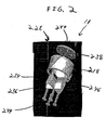
- FIG. 2 is an exploded perspective view of an embodiment of a workpiece holder incorporating features of the present invention.
- FIG. 3 is a perspective bottom diagonal view of an embodiment of a workpiece holder incorporating features of the present invention.
- FIG. 4 is a top plan view of an embodiment of a workpiece holder incorporating features of the present invention.
- FIG. 5 is a plan view of an embodiment of a workpiece holder incorporating features of the present invention.
- FIG. 1 there is shown a plan view of a system 10 incorporating features of the present invention.
- the present invention will be described with reference to the embodiment shown in the drawings, it should be understood that the present invention can be embodied in many alternate forms of embodiments.
- any suitable size, shape or type of elements or materials could be used.
- the system 10 generally comprises a workpiece holder 11 for processing a workpiece 12 in a chamber 14 of liquified fluid 16 .
- the workpiece holder 11 includes a rotator 18 having an exterior wall 20 with at least one fluid guide 22 .
- the fluid guide 22 can comprise a turbine blade 22 machined from the exterior wall 20 of the workpiece holder 11 .
- the fluid guide can be formed by creating channels 24 in the exterior wall 20 .
- a fixture 26 is coupled to the rotator 18 for securing the workpiece 12 to an end of the rotator 18 , such as the top end 28 .
- a drive motor 32 is located outside the chamber 14 .
- the drive motor 32 is used to rotate the rotator 18 .
- the drive motor 32 can be magnetically coupled to the rotator 18 .
- the drive motor 32 can be coupled to the rotator 18 in any suitable fashion, such as for example, a drive shaft.
- the drive motor 32 includes a magnetic device (not shown) located outside of the chamber 14 that allows the drive shaft to be coupled to the magnetic characteristics of the workpiece holder 14 and rotate the rotator 18 .
- the rotator 18 can be rotated at approximately 450 RPM (rotations per minute), although faster and slower rotation speeds can also mix the liquified fluid with the remaining fluid on the surface of the workpiece 12 for facilitating removal of the surface fluid.
- a drive motor 32 located outside the chamber 14 has been described and shown, the present invention is not so limited, as the drive motor 32 may be part of the chamber 14 or located wherever the drive motor 32 can rotate the workpiece holder 11 without interfering with fluid flow in the chamber 14 , without departing from the broader aspects of the present invention.
- a magnetic device in a drive motor 32 has been described, the present invention is not so limited, as any device or process which generates a sufficient magnetic field to securely couple to the rotator 18 , and which can cause rotation at a sufficient speed, can be used as a drive motor 32 , without departing from the broader aspects of the present invention.
- a rotator 218 can comprise a cylindrically-shaped shell with an interior aperture 234 . While a rotator 18 having a cylindrically shaped shell has been shown and described, in alternate embodiments, the rotator can have a solid form incorporating the sample holder surface without departing from the broader aspects of the present invention.
- the rotator 18 can have magnetic characteristics for coupling to the magnet of the drive motor 32 .
- a magnetic device 236 such as a symmetrical cross shaped magnet 236 , can be secured in the interior aperture 234 of the rotator 218 .
- the rotator 18 can be a solid object with a magnet coupled to the bottom end 30 of the rotator 18 .
- the magnet 236 is adapted to provide the rotator 218 with the magnetic characteristics for coupling the rotator 218 to the drive motor 32 and rotating the rotator 18 .
- the magnet 236 can be secured to the rotator 218 with screws 244 . In alternate embodiments, the magnet 236 can be secured in any suitable fashion other than including screws. While a cross shape for a magnet 236 has been shown, the magnet 236 can be any shape which turns concentrically about the axis of the rotator 18 .
- the screws 244 can be inserted into a sample holder 238 which can be inserted into the top end 228 of the rotator 218 .
- the sample holder 238 generally provides a surface area 240 on the top end of the rotator 218 .
- An interior wall 246 of the rotator 218 can have a flange (not shown) for supporting the sample holder 238 .
- the rotator 218 , sample holder 238 , magnet 236 and screws 244 can be made of stainless steel, although any other suitable material can be used without departing from the broader aspects of the present invention.
- the rotator 218 and the magnet 236 can be coated with, for example, PTFE (TeflonTM) to reduce friction characteristics of the rotator 218 and magnet 236 for facilitating the rotation of the rotator 218 .
- a fixture 426 can be coupled to a sample holder 438 for securing the workpiece 12 to the top end of the rotator 418 .
- the fixture 426 can include a clamp 446 including a clamp screw 448 for securing a retaining device 450 to the sample holder 438 .
- Other apparatus for securing a workpiece 12 to the workpiece holder 411 such as a locking ring or a vacuum device, can also be used without departing from the broader aspects of the present invention.
- the turbine blades 22 are set at an angle to the axis of the cylindrically-shaped rotator. While a particular angle has been shown, the angle can vary without departing from the broader aspects of the present invention. In addition, while the turbine blades 22 are shown extending from one end of the rotator 18 to the other end of the rotator 18 , the present invention is not so limited. In alternate embodiments, the turbine blades 22 can begin partially up the rotator and extend to the top end 28 of the rotator, without departing from the broader aspects of the present invention.
- FIGS. 1 and 4 show the turbine blades 22 having straight edges, the present invention is not so limited, as the turbine blades 22 can have curved edges without departing from the broader aspects of the present invention.
- a rotator 18 having fluid guides which are machined from the rotator has been shown and described, the present invention is not so limited.
- the fluid guides 22 can include at least one vane or blade coupled, or otherwise attached, to the exterior wall 20 of the rotator 18 without departing from the broader aspects of the present invention.
- the workpiece 12 can be a wafer, such as a patterned exposed photoresist coated semiconductor wafer, having a relatively flat top surface.
- the workpiece 12 may also be any other shape with a flat top surface, or can include other non flat workpieces which can be secured to the workpiece holder 11 .
- the diameter of the workpiece holder 11 can be adjusted to accommodate the size of the workpiece 12 for processing with the liquified fluid 16 , and the size of the workpiece holder 11 can be adjusted to the size of the chamber 14 .
- the workpiece holder 11 is not limited to a single workpiece 12 secured on the sample holder. In alternate embodiments, multiple workpieces 12 can be secured to the rotator 18 without departing from the broader aspects of the present invention.
- the liquified fluid 16 can include supercritical carbon dioxide.
- the liquified fluid can also include other adjuvants, such as surface active agents which can form a ternary mutual micelle with water and carbon dioxide.
- the other adjuvants can be co-solvents, such as for example, xylene or fluorocarbon.
- the co-solvents can be used to extract the surface water for the resist by inducing a condition of low surface tension of less than 1 d/cm.
- the liquified fluid 16 can generally fill the chamber 14 .
- the chamber 14 can be a high pressure reactor, which can be pressurized to about 3000 PSI (pounds per square inch).
- the chamber 14 can also be unpressurized or pressurized to higher and lower pressures, such as 6000 PSI, without departing from the broader aspects of the present invention.
- the chamber 14 can be generally circular in shape around the rotator 18 .
- the diameter of the chamber 14 surrounding, or partially surrounding, the rotator 18 can closely match the diameter of the rotator 18 .
- the diameter of the chamber 14 surrounding, or partially surrounding, the rotator 18 can be irrelevant to the diameter of the rotator 18 , as long as sufficient clearance is provided to allow the rotator 18 to rotate and direct the liquified fluid 16 .
- the chamber 14 can contain more than one workpiece holder 11 .
- another embodiment of the present invention includes a fluid flow driver 532 for rotating the rotator 518 .
- the fluid flow driver 532 includes apparatus 552 for inserting liquified fluid 516 at the bottom end 530 of the rotator 518 .
- the flow of the liquified fluid 516 from the bottom end 530 of the rotator 518 to the top end 528 of the rotator 518 exerts force on the fluid guide 522 and rotate the rotator 518 within the chamber 514 of liquified fluid 516 .
- the rotation directs the liquified fluid 516 perpendicular to the top end 528 of the rotator 518 and across the workpiece 512 .
- fluid flow driver 532 and magnetic drive motor 32 have been shown and described, the present invention is not so limited, as any method of rotating the workpiece holder 11 without interfering with the liquified fluid flow can be used without departing from the broader aspects of the present invention.
- the workpiece 12 such as a wafer 12
- the rotator 18 is placed inside the high pressure process chamber 14 .
- the chamber 14 is filled with liquified fluids 16 , such as supercritical carbon dioxide, and the workpiece 12 is simultaneously rotated inside the chamber 14 .
- the rotator 18 rotates and directs the liquified fluid 16 from the bottom end 30 of the rotator 18 to the top end 28 of the rotator 18 .
- the rotation causes a centrifugal process which agitates and mixes the liquified fluid 16 with surface fluid, such as water, latent developer and solvent, remaining on the workpiece 12 from the fabrication process.
- the centrifugal process directs the liquified fluid 16 across and away from the workpiece 12 , removing more of the remaining surface fluid from the workpiece 12 .
- the liquified fluid 16 is also mixed and directed perpendicular to the surface of the top end 28 of the rotator 18 , resulting in further mixing of the liquified fluid 16 with the remaining surface fluid on the workpiece 12 .
- the mixing lowers the surface tension of the remaining surface fluid, which speeds up the removal of the remaining surface fluid from the workpiece 12 , reducing image collapse.
- the use of the workpiece holder 11 is at least twice as effective in preventing occurrences of image collapse as previous methods of removing surface fluid from a workpiece 12 .
- a wafer coated with positive KRS photoresist (See U.S. Pat. No. 6,001,418, herein incorporated by reference) with a thickness of 0.8 micrometer was coated on a silicon wafer.
- the wafer was exposed by a 25 KV electron beam to a pattern of 150 nanometer lines with adjacent 300 nanometer spaces.
- the exposed wafer was developed in 0.263 N TMAH, rinsed with water and kept wet and placed in the high pressure process chamber.
- the wafer piece was held horizontally on a flat chuck (that is, no vanes or blades) and the flat chuck was rotated with an external magnet while the process chamber was filled with supercritical CO 2 . After processing and opening to atmosphere, the image features show collapse.
- the workpiece holder 11 is particularly advantageous for thin film processing, cleaning, and other processes where it is desirable to have a liquified fluid flow directed axially with respect to the surface of the workpiece 12 to be cleaned.
- an application of the workpiece holder 11 can include removing water from the surface of a developed but wet rinsed resist 12 to prevent image collapse.
- the use of the workpiece holder 11 can remove or reduce surface water remaining on the workpiece to less than a 10 um thick layer which facilitates solubilization by the liquified fluid, such as liquified CO 2 and/or an emulsifying agent or co-solvent. The less water present on the workpiece surface the easier it is to remove the water.
- the workpiece holder 11 combines two features of a reactor, directed flow and fluid agitation for mixing, into a single part.
- the rotator 18 can be scaled to 300 mm workpieces 12 , such as wafers.
- the workpiece holder 11 can also improve the cleaning of the surface of a wafer with supercritical fluids by providing centrifugal transport of removed particulates from the workpiece 12 as the surface is cleaned, and providing fresh supercritical fluids, such as a cleaning agent, at the surface of the workpiece 12 .
Landscapes
- Cleaning Or Drying Semiconductors (AREA)
Abstract
Description
- 1. Field of the Invention
- The present invention relates to workpiece mounting devices and, more particularly, to a device for mounting workpieces that facilitates their treatment by a fluid mixture.
- 2. Brief Description of Related Developments
- Designs for treating workpieces, such as for example, wafers or parts to be cleaned, in a fluid mixture generally use active stirring mechanisms physically separate from the workpiece mounting. In thin film processing, cleaning and other processes, it is generally desirable to have flow directed axially with respect to the surface of the workpiece.
- In the process of fabricating a semiconductor device, a predetermined pattern is transferred to or drawn on a resist film covering the surface of a semiconductor substrate. The fabrication process uses water and aqueous bases for developing or rinsing the created photoresist pattern, and rinsing off strippers and slurries. The remaining surface liquid, such as water, can cause a collapse of the resist pattern during the evaporation of the surface liquid. This image collapse is due to the high surface tension of the surface liquid.
- In order to reduce image collapse, liquified, or supercritical, carbon dioxide (SCCO 2) having a very low surface tension is mixed with the surface liquid remaining on the semiconductor device to remove the surface liquid from the semiconductor device. As carbon dioxide is not very soluble in water, an additional emulsifying agent, or agents, can be added to the liquified carbon dioxide to aid in inducing a low surface tension in the water. The additional agent needs to be mixed with the liquified carbon dioxide, or the combination of the liquified carbon dioxide and the agent, must be mixed with the surface water. While some mixing methods have been used to stir the liquified fluid with the surface liquid, image collapse due to the high surface tension is still a problem. In addition, reducing image collapse is becoming more important as semiconductor devices become larger with more complex resist patterns, and the resist patterns are including patterns of lines and spaces which are decreasing in size.
- It would be advantageous to be able to facilitate the processing of semiconductor devices with a liquified fluid mixture and provide fluid agitation for mixing and directed flow into a single part.
- The present invention is directed to a workpiece holder for processing a workpiece in a chamber of a liquified fluid. In one embodiment, the workpiece holder includes a cylindrically shaped rotator having an exterior wall and at least one fluid guide on the exterior wall. The rotator is adapted to rotate and provide fluid flow across a first end of the rotator, and is adapted to provide fluid flow and mixing perpendicular to a surface of the first end of the rotator. A fixture is coupled to the first end of the rotator for securing the workpiece to the first end of the rotator.
- In one aspect, the present invention is directed to a method of processing a workpiece in a chamber of liquified fluid. In one embodiment, the method includes providing a workpiece holder including a cylindrically shaped rotator having an exterior wall and at least one fluid guide on the exterior wall, the rotator adapted to rotate and provide fluid flow across a first end of the rotator. The step of providing the workpiece holder also includes a fixture coupled to the first end of the rotator for securing the workpiece to the first end of the rotator. The method further includes securing the workpiece to the first end of the cylindrically shaped rotator with the fixture, and rotating the workpiece holder, wherein the at least one fluid guide mixes and agitates the liquified fluid and directs the liquified fluid perpendicular to a surface of the first end of the rotator to remove surface fluid from the workpiece and preventing image collapse of the workpiece.
- The foregoing aspects and other features of the present invention are explained in the following description, taken in connection with the accompanying drawings, wherein:
- FIG. 1 is a plan view of an embodiment of a workpiece holder incorporating features of the present invention.
- FIG. 2 is an exploded perspective view of an embodiment of a workpiece holder incorporating features of the present invention.
- FIG. 3 is a perspective bottom diagonal view of an embodiment of a workpiece holder incorporating features of the present invention.
- FIG. 4 is a top plan view of an embodiment of a workpiece holder incorporating features of the present invention.
- FIG. 5 is a plan view of an embodiment of a workpiece holder incorporating features of the present invention.
- Referring to FIG. 1, there is shown a plan view of a
system 10 incorporating features of the present invention. Although the present invention will be described with reference to the embodiment shown in the drawings, it should be understood that the present invention can be embodied in many alternate forms of embodiments. In addition, any suitable size, shape or type of elements or materials could be used. - As shown in FIG. 1, the
system 10 generally comprises a workpiece holder 11 for processing a workpiece 12 in achamber 14 of liquifiedfluid 16. The workpiece holder 11 includes arotator 18 having anexterior wall 20 with at least onefluid guide 22. Thefluid guide 22 can comprise aturbine blade 22 machined from theexterior wall 20 of the workpiece holder 11. In one embodiment, the fluid guide can be formed by creatingchannels 24 in theexterior wall 20. Afixture 26 is coupled to therotator 18 for securing the workpiece 12 to an end of therotator 18, such as thetop end 28. - As shown in FIG. 1, a
drive motor 32 is located outside thechamber 14. Thedrive motor 32 is used to rotate therotator 18. In one embodiment as shown in FIG. 1, thedrive motor 32 can be magnetically coupled to therotator 18. In alternate embodiments, thedrive motor 32 can be coupled to therotator 18 in any suitable fashion, such as for example, a drive shaft. Thedrive motor 32 includes a magnetic device (not shown) located outside of thechamber 14 that allows the drive shaft to be coupled to the magnetic characteristics of theworkpiece holder 14 and rotate therotator 18. Therotator 18 can be rotated at approximately 450 RPM (rotations per minute), although faster and slower rotation speeds can also mix the liquified fluid with the remaining fluid on the surface of the workpiece 12 for facilitating removal of the surface fluid. - While a
drive motor 32 located outside thechamber 14 has been described and shown, the present invention is not so limited, as thedrive motor 32 may be part of thechamber 14 or located wherever thedrive motor 32 can rotate the workpiece holder 11 without interfering with fluid flow in thechamber 14, without departing from the broader aspects of the present invention. Moreover, while a magnetic device in adrive motor 32 has been described, the present invention is not so limited, as any device or process which generates a sufficient magnetic field to securely couple to therotator 18, and which can cause rotation at a sufficient speed, can be used as adrive motor 32, without departing from the broader aspects of the present invention. - Referring to FIGS. 2 and 3, in one embodiment, a
rotator 218 can comprise a cylindrically-shaped shell with aninterior aperture 234. While arotator 18 having a cylindrically shaped shell has been shown and described, in alternate embodiments, the rotator can have a solid form incorporating the sample holder surface without departing from the broader aspects of the present invention. Therotator 18 can have magnetic characteristics for coupling to the magnet of thedrive motor 32. For example, amagnetic device 236, such as a symmetrical cross shapedmagnet 236, can be secured in theinterior aperture 234 of therotator 218. In an alternate embodiment, therotator 18 can be a solid object with a magnet coupled to thebottom end 30 of therotator 18. - The
magnet 236 is adapted to provide therotator 218 with the magnetic characteristics for coupling therotator 218 to thedrive motor 32 and rotating therotator 18. Themagnet 236 can be secured to therotator 218 withscrews 244. In alternate embodiments, themagnet 236 can be secured in any suitable fashion other than including screws. While a cross shape for amagnet 236 has been shown, themagnet 236 can be any shape which turns concentrically about the axis of therotator 18. - Continuing with FIGS. 2 and 3, the
screws 244 can be inserted into asample holder 238 which can be inserted into thetop end 228 of therotator 218. Thesample holder 238 generally provides asurface area 240 on the top end of therotator 218. Aninterior wall 246 of therotator 218 can have a flange (not shown) for supporting thesample holder 238. - Continuing with FIGS. 2 and 3, the
rotator 218,sample holder 238,magnet 236 andscrews 244 can be made of stainless steel, although any other suitable material can be used without departing from the broader aspects of the present invention. In addition, therotator 218 and themagnet 236 can be coated with, for example, PTFE (Teflon™) to reduce friction characteristics of therotator 218 andmagnet 236 for facilitating the rotation of therotator 218. - Referring to FIGS. 1 and 4, a fixture 426 can be coupled to a
sample holder 438 for securing the workpiece 12 to the top end of therotator 418. The fixture 426 can include aclamp 446 including aclamp screw 448 for securing aretaining device 450 to thesample holder 438. Other apparatus for securing a workpiece 12 to theworkpiece holder 411, such as a locking ring or a vacuum device, can also be used without departing from the broader aspects of the present invention. - As shown in FIGS. 1 and 4, the
turbine blades 22 are set at an angle to the axis of the cylindrically-shaped rotator. While a particular angle has been shown, the angle can vary without departing from the broader aspects of the present invention. In addition, while theturbine blades 22 are shown extending from one end of therotator 18 to the other end of therotator 18, the present invention is not so limited. In alternate embodiments, theturbine blades 22 can begin partially up the rotator and extend to thetop end 28 of the rotator, without departing from the broader aspects of the present invention. - While FIGS. 1 and 4 show the
turbine blades 22 having straight edges, the present invention is not so limited, as theturbine blades 22 can have curved edges without departing from the broader aspects of the present invention. Furthermore, while arotator 18 having fluid guides which are machined from the rotator has been shown and described, the present invention is not so limited. In alternate embodiments, the fluid guides 22 can include at least one vane or blade coupled, or otherwise attached, to theexterior wall 20 of therotator 18 without departing from the broader aspects of the present invention. - Referring to FIG. 1, the workpiece 12 can be a wafer, such as a patterned exposed photoresist coated semiconductor wafer, having a relatively flat top surface. The workpiece 12 may also be any other shape with a flat top surface, or can include other non flat workpieces which can be secured to the workpiece holder 11. The diameter of the workpiece holder 11 can be adjusted to accommodate the size of the workpiece 12 for processing with the
liquified fluid 16, and the size of the workpiece holder 11 can be adjusted to the size of thechamber 14. In addition, the workpiece holder 11 is not limited to a single workpiece 12 secured on the sample holder. In alternate embodiments, multiple workpieces 12 can be secured to therotator 18 without departing from the broader aspects of the present invention. - Continuing with FIG. 1, the
liquified fluid 16 can include supercritical carbon dioxide. In alternate embodiments, the liquified fluid can also include other adjuvants, such as surface active agents which can form a ternary mutual micelle with water and carbon dioxide. The other adjuvants can be co-solvents, such as for example, xylene or fluorocarbon. The co-solvents can be used to extract the surface water for the resist by inducing a condition of low surface tension of less than 1 d/cm. In one embodiment, theliquified fluid 16 can generally fill thechamber 14. - As shown in FIG. 1, the
chamber 14 can be a high pressure reactor, which can be pressurized to about 3000 PSI (pounds per square inch). Thechamber 14 can also be unpressurized or pressurized to higher and lower pressures, such as 6000 PSI, without departing from the broader aspects of the present invention. Thechamber 14 can be generally circular in shape around therotator 18. In one embodiment, the diameter of thechamber 14 surrounding, or partially surrounding, therotator 18 can closely match the diameter of therotator 18. In alternate embodiments, the diameter of thechamber 14 surrounding, or partially surrounding, therotator 18 can be irrelevant to the diameter of therotator 18, as long as sufficient clearance is provided to allow therotator 18 to rotate and direct theliquified fluid 16. In a further embodiment, thechamber 14 can contain more than one workpiece holder 11. - As shown in FIG. 5, another embodiment of the present invention includes a
fluid flow driver 532 for rotating therotator 518. Thefluid flow driver 532 includesapparatus 552 for insertingliquified fluid 516 at thebottom end 530 of therotator 518. The flow of the liquified fluid 516 from thebottom end 530 of therotator 518 to thetop end 528 of therotator 518 exerts force on thefluid guide 522 and rotate therotator 518 within the chamber 514 of liquifiedfluid 516. The rotation directs theliquified fluid 516 perpendicular to thetop end 528 of therotator 518 and across the workpiece 512. While thefluid flow driver 532 andmagnetic drive motor 32 have been shown and described, the present invention is not so limited, as any method of rotating the workpiece holder 11 without interfering with the liquified fluid flow can be used without departing from the broader aspects of the present invention. - Referring to FIG. 1, in operation, the workpiece 12, such as a wafer 12, is affixed to the
rotator 18, and therotator 18 is placed inside the highpressure process chamber 14. Thechamber 14 is filled with liquifiedfluids 16, such as supercritical carbon dioxide, and the workpiece 12 is simultaneously rotated inside thechamber 14. - Continuing with FIG. 1, the
rotator 18 rotates and directs the liquified fluid 16 from thebottom end 30 of therotator 18 to thetop end 28 of therotator 18. The rotation causes a centrifugal process which agitates and mixes theliquified fluid 16 with surface fluid, such as water, latent developer and solvent, remaining on the workpiece 12 from the fabrication process. The centrifugal process directs theliquified fluid 16 across and away from the workpiece 12, removing more of the remaining surface fluid from the workpiece 12. - The liquified
fluid 16 is also mixed and directed perpendicular to the surface of thetop end 28 of therotator 18, resulting in further mixing of the liquified fluid 16 with the remaining surface fluid on the workpiece 12. The mixing lowers the surface tension of the remaining surface fluid, which speeds up the removal of the remaining surface fluid from the workpiece 12, reducing image collapse. The use of the workpiece holder 11 is at least twice as effective in preventing occurrences of image collapse as previous methods of removing surface fluid from a workpiece 12. - In a comparison showing the improvement provided by the workpiece holder 11 of the present invention, a wafer coated with positive KRS photoresist (See U.S. Pat. No. 6,001,418, herein incorporated by reference) with a thickness of 0.8 micrometer was coated on a silicon wafer. The wafer was exposed by a 25 KV electron beam to a pattern of 150 nanometer lines with adjacent 300 nanometer spaces. The exposed wafer was developed in 0.263 N TMAH, rinsed with water and kept wet and placed in the high pressure process chamber. The wafer piece was held horizontally on a flat chuck (that is, no vanes or blades) and the flat chuck was rotated with an external magnet while the process chamber was filled with supercritical CO2. After processing and opening to atmosphere, the image features show collapse.
- In contrast, a similar wafer coated with KRS photoresist was processed in an identical manner, except that the wafer piece was affixed to the workpiece holder 11. After identical processing and rotating with the workpiece holder 11, the image features showed no collapse.
- The workpiece holder 11 is particularly advantageous for thin film processing, cleaning, and other processes where it is desirable to have a liquified fluid flow directed axially with respect to the surface of the workpiece 12 to be cleaned. For example, an application of the workpiece holder 11 can include removing water from the surface of a developed but wet rinsed resist 12 to prevent image collapse. The use of the workpiece holder 11 can remove or reduce surface water remaining on the workpiece to less than a 10 um thick layer which facilitates solubilization by the liquified fluid, such as liquified CO2 and/or an emulsifying agent or co-solvent. The less water present on the workpiece surface the easier it is to remove the water.
- Furthermore, the workpiece holder 11 combines two features of a reactor, directed flow and fluid agitation for mixing, into a single part. Moreover, the
rotator 18 can be scaled to 300 mm workpieces 12, such as wafers. The workpiece holder 11 can also improve the cleaning of the surface of a wafer with supercritical fluids by providing centrifugal transport of removed particulates from the workpiece 12 as the surface is cleaned, and providing fresh supercritical fluids, such as a cleaning agent, at the surface of the workpiece 12. - It should be understood that the foregoing description is only illustrative of the invention. Various alternatives and modifications can be devised by those skilled in the art without departing from the invention. Accordingly, the present invention is intended to embrace all such alternatives, modifications and variances which fall within the scope of the appended claims.
Claims (28)
Priority Applications (1)
| Application Number | Priority Date | Filing Date | Title |
|---|---|---|---|
| US10/120,309 US6736906B2 (en) | 2002-04-10 | 2002-04-10 | Turbine part mount for supercritical fluid processor |
Applications Claiming Priority (1)
| Application Number | Priority Date | Filing Date | Title |
|---|---|---|---|
| US10/120,309 US6736906B2 (en) | 2002-04-10 | 2002-04-10 | Turbine part mount for supercritical fluid processor |
Publications (2)
| Publication Number | Publication Date |
|---|---|
| US20030192575A1 true US20030192575A1 (en) | 2003-10-16 |
| US6736906B2 US6736906B2 (en) | 2004-05-18 |
Family
ID=28790077
Family Applications (1)
| Application Number | Title | Priority Date | Filing Date |
|---|---|---|---|
| US10/120,309 Expired - Lifetime US6736906B2 (en) | 2002-04-10 | 2002-04-10 | Turbine part mount for supercritical fluid processor |
Country Status (1)
| Country | Link |
|---|---|
| US (1) | US6736906B2 (en) |
Cited By (1)
| Publication number | Priority date | Publication date | Assignee | Title |
|---|---|---|---|---|
| WO2005097363A1 (en) * | 2004-04-05 | 2005-10-20 | Sc Fluid Technologies, Inc. | Loadbearing platform with fluid support, isolation and rotation |
Families Citing this family (8)
| Publication number | Priority date | Publication date | Assignee | Title |
|---|---|---|---|---|
| US6848458B1 (en) | 2002-02-05 | 2005-02-01 | Novellus Systems, Inc. | Apparatus and methods for processing semiconductor substrates using supercritical fluids |
| US20080264443A1 (en) * | 2002-02-05 | 2008-10-30 | Novellus Systems, Inc. | Apparatus and methods for increasing the rate of solute concentration evolution in a supercritical process chamber |
| WO2004064121A2 (en) * | 2003-01-10 | 2004-07-29 | S.C. Fluids Inc. | A supercritical fluid cleaning system and method |
| US7108001B2 (en) * | 2003-04-03 | 2006-09-19 | Keith Pope | Method and apparatus for rotation of a workpiece in supercritical fluid solutions for removing photo resist, residues and particles therefrom |
| CA2552717C (en) * | 2004-01-07 | 2011-11-29 | Levtech, Inc. | Mixing bag with integral sparger and sensor receiver |
| DK1773976T4 (en) | 2004-06-04 | 2020-02-10 | Global Life Sciences Solutions Usa Llc | SINGLE-BORE ACTOR SYSTEMS AND PROCEDURES |
| US7407554B2 (en) * | 2005-04-12 | 2008-08-05 | International Business Machines Corporation | Development or removal of block copolymer or PMMA-b-S-based resist using polar supercritical solvent |
| US9339026B2 (en) | 2012-06-14 | 2016-05-17 | Therapeutic Proteins International, LLC | Pneumatically agitated and aerated single-use bioreactor |
Citations (3)
| Publication number | Priority date | Publication date | Assignee | Title |
|---|---|---|---|---|
| US556604A (en) * | 1896-03-17 | Dish-cleaner | ||
| US1049896A (en) * | 1912-07-13 | 1913-01-07 | Mary E Miller | Dish-washing machine. |
| US6401734B1 (en) * | 1999-03-11 | 2002-06-11 | Hitachi Kokusai Electric Inc. | Substrate treating apparatus |
Family Cites Families (3)
| Publication number | Priority date | Publication date | Assignee | Title |
|---|---|---|---|---|
| EP0671662B1 (en) | 1994-02-24 | 1999-01-20 | Nec Corporation | Method for developing a resist pattern |
| US6001418A (en) | 1997-12-16 | 1999-12-14 | The University Of North Carolina At Chapel Hill | Spin coating method and apparatus for liquid carbon dioxide systems |
| US6277753B1 (en) | 1998-09-28 | 2001-08-21 | Supercritical Systems Inc. | Removal of CMP residue from semiconductors using supercritical carbon dioxide process |
-
2002
- 2002-04-10 US US10/120,309 patent/US6736906B2/en not_active Expired - Lifetime
Patent Citations (3)
| Publication number | Priority date | Publication date | Assignee | Title |
|---|---|---|---|---|
| US556604A (en) * | 1896-03-17 | Dish-cleaner | ||
| US1049896A (en) * | 1912-07-13 | 1913-01-07 | Mary E Miller | Dish-washing machine. |
| US6401734B1 (en) * | 1999-03-11 | 2002-06-11 | Hitachi Kokusai Electric Inc. | Substrate treating apparatus |
Cited By (1)
| Publication number | Priority date | Publication date | Assignee | Title |
|---|---|---|---|---|
| WO2005097363A1 (en) * | 2004-04-05 | 2005-10-20 | Sc Fluid Technologies, Inc. | Loadbearing platform with fluid support, isolation and rotation |
Also Published As
| Publication number | Publication date |
|---|---|
| US6736906B2 (en) | 2004-05-18 |
Similar Documents
| Publication | Publication Date | Title |
|---|---|---|
| US8075702B2 (en) | Resist removing method and resist removing apparatus | |
| US7785421B2 (en) | Substrate treatment method and substrate treatment apparatus | |
| US6736906B2 (en) | Turbine part mount for supercritical fluid processor | |
| US8747611B2 (en) | Apparatus and method for treating substrate, and injection head used in the Apparatus | |
| US10854479B2 (en) | Substrate processing method and substrate processing device | |
| JP5242508B2 (en) | Liquid processing apparatus, liquid processing method, and storage medium | |
| JP4358486B2 (en) | High pressure processing apparatus and high pressure processing method | |
| JP2009110985A (en) | Substrate processing method and substrate processing apparatus | |
| US20160070171A1 (en) | Developing method, developing apparatus and storage medium | |
| JP5192853B2 (en) | Substrate processing method and substrate processing apparatus | |
| US20050124518A1 (en) | Substrate treating apparatus | |
| US6548228B2 (en) | Method of and apparatus for developing exposed photoresist to prevent impurity from being attached to wafer surface | |
| JP2002170803A (en) | Substrate processing equipment | |
| US20030140949A1 (en) | Substrate treating method and substrate treating apparatus | |
| JP2008277576A (en) | Method and apparatus for treating substrate | |
| JP2893159B2 (en) | Processing method and processing apparatus | |
| JP2006156919A (en) | Method of dislodging organic coating and remover | |
| JPH0945651A (en) | Resist cleaning device and developing device | |
| US20040094187A1 (en) | Apparatus and method for holding a semiconductor wafer using centrifugal force | |
| CN117046635A (en) | Fluid supply nozzle for semiconductor substrate processing and semiconductor substrate processing apparatus | |
| JP4347765B2 (en) | Substrate processing equipment | |
| JP2002329773A (en) | Spin processing device | |
| JP2003243349A (en) | Substrate processing method | |
| JP2005158861A (en) | Rotary processing apparatus and semiconductor device manufacturing method | |
| JP2008016781A (en) | Substrate processing method and substrate processing apparatus |
Legal Events
| Date | Code | Title | Description |
|---|---|---|---|
| AS | Assignment |
Owner name: INTERNATIONAL BUSINESS MACHINES CORPORATION, NEW Y Free format text: ASSIGNMENT OF ASSIGNORS INTEREST;ASSIGNORS:COTTE, JOHN M.;FLOTTA, MATTEO;MCCULLOUGH, KENNETH J;AND OTHERS;REEL/FRAME:012794/0813;SIGNING DATES FROM 20020401 TO 20020404 |
|
| STCF | Information on status: patent grant |
Free format text: PATENTED CASE |
|
| FPAY | Fee payment |
Year of fee payment: 4 |
|
| AS | Assignment |
Owner name: GOOGLE INC., CALIFORNIA Free format text: ASSIGNMENT OF ASSIGNORS INTEREST;ASSIGNOR:INTERNATIONAL BUSINESS MACHINES CORPORATION;REEL/FRAME:026894/0001 Effective date: 20110817 |
|
| FPAY | Fee payment |
Year of fee payment: 8 |
|
| FPAY | Fee payment |
Year of fee payment: 12 |
|
| AS | Assignment |
Owner name: GOOGLE LLC, CALIFORNIA Free format text: CHANGE OF NAME;ASSIGNOR:GOOGLE INC.;REEL/FRAME:044127/0735 Effective date: 20170929 |