US200044A - Improvement in wagon-jacks - Google Patents
Improvement in wagon-jacks Download PDFInfo
- Publication number
- US200044A US200044A US200044DA US200044A US 200044 A US200044 A US 200044A US 200044D A US200044D A US 200044DA US 200044 A US200044 A US 200044A
- Authority
- US
- United States
- Prior art keywords
- pin
- pawl
- ratchet
- standard
- wagon
- Prior art date
- Legal status (The legal status is an assumption and is not a legal conclusion. Google has not performed a legal analysis and makes no representation as to the accuracy of the status listed.)
- Expired - Lifetime
Links
- 239000002184 metal Substances 0.000 description 2
- 238000005452 bending Methods 0.000 description 1
- 238000004904 shortening Methods 0.000 description 1
- 239000007787 solid Substances 0.000 description 1
Images

Classifications
-
- B—PERFORMING OPERATIONS; TRANSPORTING
- B66—HOISTING; LIFTING; HAULING
- B66F—HOISTING, LIFTING, HAULING OR PUSHING, NOT OTHERWISE PROVIDED FOR, e.g. DEVICES WHICH APPLY A LIFTING OR PUSHING FORCE DIRECTLY TO THE SURFACE OF A LOAD
- B66F15/00—Crowbars or levers
Definitions
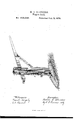
- a solid bloclrbase to which is bolted a standard composed of two vertical parallel bars, between which bars vibrate the lever and pawl-staff, said staff having a crosspin catching into a ratchet, which is formed of metal plates planted on said bars, and projecting from the edge of the standard, and from which ratchet, as the pin passes up the standard, it is kept off by a vertical rod-fender. Outside of this fender is a double-incline slide, guiding the pin to and up the same, all of which is described as follows:
- B represents the base of the invention, to which are bolted two opposite vertical'bars, b b, forming the standard S, and leaving between the bars a full-length slot or aperture, t.
- This slot vibrate the lever L and pawl-staft' P-the lever on the fulcrum-pin p, the pawl-stai bya loose connection with the under side of thelever.
- the ratchet R is formed by planting ⁇ toothed metal strips, about two by three-sixteenths inches in size, on the innerface of said bars, having the full depth of the teeth projecting in front. At the outward end of the pawl-staff is the cross-pin fn, catching said teeth, and thereby sustaining the raised vehicle.
- F is a rod-spring, rigidly attached to the standard at r, from which point it extends out horizontally to about one-fourth of an inch in front of a plane of the teeth-points; then at right angles inward to a point about in front of the left ratchetplate; thence down to a little below the ratchet, bending at the same time, to give springing properties to the rod inward more than parallel to the standard.
- One end of the sloped-edge plate I is attached, Vedge up, to the inner face of the left bar of the standard, at the lower end of the ratchet, and the other is fastened in a mortise in the base of the jack. On the lower edge of said plate, at a point where the rod, when in -position, is parallel to the face of the standard,
- the paWl-pin,in passing; up outside of the said fender, enables the device to be operated by only one hand.
Landscapes
- Life Sciences & Earth Sciences (AREA)
- Engineering & Computer Science (AREA)
- Geology (AREA)
- Mechanical Engineering (AREA)
- Structural Engineering (AREA)
- Bending Of Plates, Rods, And Pipes (AREA)
- Body Structure For Vehicles (AREA)
Description
M. C. FLANDERSlv Wagon-Jack.
No.' 200,044. Patented Feb. 5,1878.
UNITED SrArEsPAr-Elv'r Orr-1on- MARVIN O. FLANDERS, OF KENDLL, NEW YORK.
IMPROVEMENT IN WAGON-JACKS.
Specification forming part of Letters Patent No. 200,044, dated February 5, 1878; application iiled December 15,1877.
To all rwhom it may concern:
Be it known that I, MARvrNAC. FLANDERS of the town of Kendall, in the county of Orleans and State of New York, have invented new and useful Improvements in Vagon-Jacks, which improvements are fully set forth in the following specification and accompanying drawing, which drawing is aperspective view of my improved wagon-jack.
This invention relates to that class'of wagonjacks whereof the lever and pawl-rod vibrate between two upright bars, which form the standard, and the pawl-pin catches teeth. projecting from the front of the standards edge, and then, in passing up the teeth, is warded off by a fender. Its object is to furnish a simple and cheap device, by which the pawl-pin, after descending below the ratchet, can, without catching in or being obstructed by it, be, by the lever, raised above the same.
It consists in a solid bloclrbase, to which is bolted a standard composed of two vertical parallel bars, between which bars vibrate the lever and pawl-staff, said staff having a crosspin catching into a ratchet, which is formed of metal plates planted on said bars, and projecting from the edge of the standard, and from which ratchet, as the pin passes up the standard, it is kept off by a vertical rod-fender. Outside of this fender is a double-incline slide, guiding the pin to and up the same, all of which is described as follows:
In the drawing, B represents the base of the invention, to which are bolted two opposite vertical'bars, b b, forming the standard S, and leaving between the bars a full-length slot or aperture, t. In this slot vibrate the lever L and pawl-staft' P-the lever on the fulcrum-pin p, the pawl-stai bya loose connection with the under side of thelever. The ratchet R is formed by planting` toothed metal strips, about two by three-sixteenths inches in size, on the innerface of said bars, having the full depth of the teeth projecting in front. At the outward end of the pawl-staff is the cross-pin fn, catching said teeth, and thereby sustaining the raised vehicle.
F is a rod-spring, rigidly attached to the standard at r, from which point it extends out horizontally to about one-fourth of an inch in front of a plane of the teeth-points; then at right angles inward to a point about in front of the left ratchetplate; thence down to a little below the ratchet, bending at the same time, to give springing properties to the rod inward more than parallel to the standard.A One end of the sloped-edge plate I is attached, Vedge up, to the inner face of the left bar of the standard, at the lower end of the ratchet, and the other is fastened in a mortise in the base of the jack. On the lower edge of said plate, at a point where the rod, when in -position, is parallel to the face of the standard,
and far enough out from the face of the same "to give room for the pawl-pin n, in passing up or down the ratchet, to move freely between the teeth and rod, is the lug g, and the lower end of the spring-rod is brought out to rest against and be supported by said lug, and against which also, after the pawl-pin, in its descent, passes out from the rear of the spring under the same, reacts and iinpinges. This brings the spring-rod parallel to and in front of the standard, and, when the pawl-pin passes up outside of the spring, the spring becomes a fender, barring off the pin from the teeth, while the sloped-edge plate prevents said pin from fallin g below the ratchet or spring, guiding the same out from its rear, then in its course up on its outside back to the same. The angle in the plates edge is causedby shortening, to save its extension out on the base, as it otherwise would. The through-pin c' receives the weight of the pawl-sta in its fall, and prevents a fracture of the same by the pin as it strikes on the plate.
The operation of they invention is as follows: Bythe fulcrum-pinp and perforations p the lever is adjusted to the desired height. Then, in raising-the outward end of the lever, the pin n is raised and carried over the top of the fender F, and dropped between the ratchet and fender, catching the teeth at 'the right point for sustaining the wagon, the same retaining the pawl-pinin position till released by again bearing down the lever.
To release the wagon from the jack the outward end of the lever is again borne down till the pawl-pin passes out from under the fenderspring onto the incline I, when, the weight being Y withdrawn, they vehicle rests on the ground, thereby completing the operation for which the device was intended.
Its advantages are the following: The ratchet- 'plates planted on the inside face of the bars composing the standard 4strengthen the said. bars to such an extent. that they can be made smaller than otherwise. The paWl-pin,in passing; up outside of the said fender, enables the device to be operated by only one hand.
I claim as my invention and ask for Letters Patent upon-- The spring-rod fender F, angular incline Witnesses:
guide I, and lug g, by which the paWLpin is taken above the ratchet Withoutcatching in the teeth, in combination with the ratchet-plates R, standard S, level.n L, and pawl P, staple s, hasp h, pin i, fulcrum-pin p, perforations p', and base B, for the purposes, substantially shown and described.
In testimony whereof I have hereto subscribed my name this 21st day of November7 1877.
MARVIN O. FLANDERS.
BENJ. F. PARSONS, M. F. ODEA.
Publications (1)
| Publication Number | Publication Date |
|---|---|
| US200044A true US200044A (en) | 1878-02-05 |
Family
ID=2269451
Family Applications (1)
| Application Number | Title | Priority Date | Filing Date |
|---|---|---|---|
| US200044D Expired - Lifetime US200044A (en) | Improvement in wagon-jacks |
Country Status (1)
| Country | Link |
|---|---|
| US (1) | US200044A (en) |
-
0
- US US200044D patent/US200044A/en not_active Expired - Lifetime
Similar Documents
| Publication | Publication Date | Title |
|---|---|---|
| US200044A (en) | Improvement in wagon-jacks | |
| US1112723A (en) | Paper-press. | |
| US1090803A (en) | Store-ladder. | |
| US357985A (en) | Wagon end-gate | |
| US235877A (en) | Fence-hoister | |
| US116232A (en) | Improvement in lifting-jacks | |
| US14826A (en) | Method of hanging gates | |
| US193750A (en) | Improvement in gate-latches | |
| US111942A (en) | Improvement in lifting-jacks | |
| US258469A (en) | Wagon-jack | |
| US1008520A (en) | Hay-rack brake. | |
| US137363A (en) | Improvement in lifting-jacks | |
| US298574A (en) | Horse hay-fork | |
| US118097A (en) | Improvement in barrel and box-elevators | |
| US154191A (en) | Improvement in presses for hay, cotton | |
| US1026964A (en) | Mine-car-door lock. | |
| US145362A (en) | Improvement in gate-fasteners | |
| US579935A (en) | William l | |
| US113377A (en) | Improvement in combined locks and latches | |
| US336394A (en) | john s | |
| US209635A (en) | Improvement in lifting-jacks | |
| US103065A (en) | Joseph a | |
| US214249A (en) | Improvement in hoisting-jacks | |
| US84291A (en) | Improved animal-trap | |
| US571140A (en) | showaiter |