US1982963A - Anchor - Google Patents
Anchor Download PDFInfo
- Publication number
- US1982963A US1982963A US689988A US68998833A US1982963A US 1982963 A US1982963 A US 1982963A US 689988 A US689988 A US 689988A US 68998833 A US68998833 A US 68998833A US 1982963 A US1982963 A US 1982963A
- Authority
- US
- United States
- Prior art keywords
- plate
- prongs
- anchor
- stem
- ground
- Prior art date
- Legal status (The legal status is an assumption and is not a legal conclusion. Google has not performed a legal analysis and makes no representation as to the accuracy of the status listed.)
- Expired - Lifetime
Links
- 210000000078 claw Anatomy 0.000 description 4
- 238000010276 construction Methods 0.000 description 2
- 238000006073 displacement reaction Methods 0.000 description 1
- 230000037431 insertion Effects 0.000 description 1
- 238000003780 insertion Methods 0.000 description 1
Images
Classifications
-
- E—FIXED CONSTRUCTIONS
- E02—HYDRAULIC ENGINEERING; FOUNDATIONS; SOIL SHIFTING
- E02D—FOUNDATIONS; EXCAVATIONS; EMBANKMENTS; UNDERGROUND OR UNDERWATER STRUCTURES
- E02D5/00—Bulkheads, piles, or other structural elements specially adapted to foundation engineering
- E02D5/74—Means for anchoring structural elements or bulkheads
- E02D5/80—Ground anchors
- E02D5/803—Ground anchors with pivotable anchoring members
Definitions
- This invention relates to anchors for guy or bracing elements of poles and the like and has for the primary object, the provision of a device of the above stated character which may be folded for easy and quick insertion in a hole formed in the ground and when subjected to a reverse movement or a pull thereon will automatically bite into the ground and become firmly anchored therein against accidental displacement.
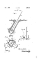
- Figure 1 is an elevational view illustrating an anchor located in a hole formed in the ground and biting into the walls of the hole and constructed in accordance with my invention.
- Figure 2 is a plan view partly in section illustrating the anchor.
- Figure 3 is a fragmentary sectional view illustrating in dotted lines a folded position of one of the prongs.
- the numeral 1 indicates a plate of ⁇ substantially triangular shape having a centrally arranged opening to receive a rod or stem 2, the latter being secured to the plate by nuts 3.
- the free end of the rod or stem is provided with an eye 4 to which a guy or bracing cable or element may be connected.
- Brackets 5 are formed integrally with one face of the plate 1 adjacent the corners of the latter and each bracket includes angularly related portions 6 between which are movably mounted claws or prongs 7.
- the claws or prongs 7 are hinged to the brackets 5 by bolts 8 on which coil springs 9 are mounted.
- each coil spring bears against the plate 1, while the other end bears against the respective prong or claw.
- the prongs or claws may be swung towards the stem 2, as shown in dotted lines in Figure 3 so that the plate and stem 00 may be inserted in a hole 10 formed in the ground and during the passing of the plate downwardly in the hole, the prongs 7 are urged against the walls of the opening so that a reverse pull on the stem will cause said prongs to bite into the ground and thereby firmly anchor the device.
- Each prong consists of a wall 11 tapered towards one end and formed integrally with side walls 12 which project beyond the non-tapered 70 end of the wall 11 and are apertured to receive the bolts 8.
- the side walls 12 taper towards the tapered end of the plate 11.
- An anchor comprising a flat plate, a stem secured to the plate centrally of the latter, brackets secured to one face of the plate and including angularly related portions, bolts connecting said portions of the brackets and located inwardly of the edges of the plate, prongs each including a wall tapered towards one end and side walls integral therewith and extending beyond the non-tapered end and apertured to receive the bolt to permitv said non-tapered end to abut the edge of the plate for limiting the movement of the prongs in one direction, and coil springs mounted on the bolts and each spring having one end bearing against its respective prong and its other end bearing against the plate.
Landscapes
- Engineering & Computer Science (AREA)
- Structural Engineering (AREA)
- Life Sciences & Earth Sciences (AREA)
- General Life Sciences & Earth Sciences (AREA)
- Mining & Mineral Resources (AREA)
- Paleontology (AREA)
- Civil Engineering (AREA)
- General Engineering & Computer Science (AREA)
- Joining Of Building Structures In Genera (AREA)
Description
Deco 4, 1934. M. C. POST 1,982,963
ANCHOR Filed sept. '18, 1933 Il s A Mraz 6200.52)
Patented Dec. 4, 1934 UNITED STATES PATENT OFFICE 1 Claim.
This invention relates to anchors for guy or bracing elements of poles and the like and has for the primary object, the provision of a device of the above stated character which may be folded for easy and quick insertion in a hole formed in the ground and when subjected to a reverse movement or a pull thereon will automatically bite into the ground and become firmly anchored therein against accidental displacement.
With these and other objects in view this invention consists in certain novel features of construction, combination and arrangement of parts to be hereinafter more fully described and claimed.
For a complete understanding of my invention, reference is to be had to the following description and accompanying drawing, in which Figure 1 is an elevational view illustrating an anchor located in a hole formed in the ground and biting into the walls of the hole and constructed in accordance with my invention.
Figure 2 is a plan view partly in section illustrating the anchor.
Figure 3 is a fragmentary sectional view illustrating in dotted lines a folded position of one of the prongs.
Referring in detail to the drawing the numeral 1 indicates a plate of` substantially triangular shape having a centrally arranged opening to receive a rod or stem 2, the latter being secured to the plate by nuts 3. The free end of the rod or stem is provided with an eye 4 to which a guy or bracing cable or element may be connected.
end of each coil spring bears against the plate 1, while the other end bears against the respective prong or claw. The prongs or claws may be swung towards the stem 2, as shown in dotted lines in Figure 3 so that the plate and stem 00 may be inserted in a hole 10 formed in the ground and during the passing of the plate downwardly in the hole, the prongs 7 are urged against the walls of the opening so that a reverse pull on the stem will cause said prongs to bite into the ground and thereby firmly anchor the device.
Each prong consists of a wall 11 tapered towards one end and formed integrally with side walls 12 which project beyond the non-tapered 70 end of the wall 11 and are apertured to receive the bolts 8. The side walls 12 taper towards the tapered end of the plate 11.
While I have shown and described the preferred embodiment of my invention, it will be understood that minor changes in construction, combination and arrangement of partsmay be made without departing from the spirit and scope of my invention as claimed.
Having described the invention, I claim:
An anchor comprising a flat plate, a stem secured to the plate centrally of the latter, brackets secured to one face of the plate and including angularly related portions, bolts connecting said portions of the brackets and located inwardly of the edges of the plate, prongs each including a wall tapered towards one end and side walls integral therewith and extending beyond the non-tapered end and apertured to receive the bolt to permitv said non-tapered end to abut the edge of the plate for limiting the movement of the prongs in one direction, and coil springs mounted on the bolts and each spring having one end bearing against its respective prong and its other end bearing against the plate.
MARVIN C. POST.
Priority Applications (1)
| Application Number | Priority Date | Filing Date | Title |
|---|---|---|---|
| US689988A US1982963A (en) | 1933-09-18 | 1933-09-18 | Anchor |
Applications Claiming Priority (1)
| Application Number | Priority Date | Filing Date | Title |
|---|---|---|---|
| US689988A US1982963A (en) | 1933-09-18 | 1933-09-18 | Anchor |
Publications (1)
| Publication Number | Publication Date |
|---|---|
| US1982963A true US1982963A (en) | 1934-12-04 |
Family
ID=24770644
Family Applications (1)
| Application Number | Title | Priority Date | Filing Date |
|---|---|---|---|
| US689988A Expired - Lifetime US1982963A (en) | 1933-09-18 | 1933-09-18 | Anchor |
Country Status (1)
| Country | Link |
|---|---|
| US (1) | US1982963A (en) |
Cited By (14)
| Publication number | Priority date | Publication date | Assignee | Title |
|---|---|---|---|---|
| US3039534A (en) * | 1959-03-16 | 1962-06-19 | Marvin C Koop | Bridge for plugging holes |
| US3116498A (en) * | 1960-03-03 | 1964-01-07 | Dow Chemical Co | Connections to expanded plastic materials |
| US4308683A (en) * | 1980-06-06 | 1982-01-05 | Lee Donald R | Trap anchoring stake |
| US4351136A (en) * | 1980-01-14 | 1982-09-28 | Raymond International Builders, Inc. | Ground anchor installation |
| WO1985003319A1 (en) * | 1984-01-30 | 1985-08-01 | Peter Alsop | Ground anchoring system |
| FR2564120A1 (en) * | 1984-05-11 | 1985-11-15 | Inst Francais Du Petrole | ANCHOR DEVICE WITH ARTICULATED ELEMENT HAVING A COUPLED SHAPE |
| US4637757A (en) * | 1984-10-12 | 1987-01-20 | Chevron Research Company | Barbed anchor pile |
| US4738063A (en) * | 1985-01-30 | 1988-04-19 | Peter Alsop | Ground anchoring system |
| US20070289811A1 (en) * | 2006-06-16 | 2007-12-20 | Brent Smith | Apparatus and method of arresting a fall |
| US20110174575A1 (en) * | 2010-01-15 | 2011-07-21 | Sidla James G | Tank Lifeline System |
| US20110303484A1 (en) * | 2010-06-10 | 2011-12-15 | Stoffels Richard B | Safety Apparatus for Arresting A Fall of A Worker |
| US20150121777A1 (en) * | 2012-05-03 | 2015-05-07 | Blue Systems AB a corporation | Anchor & method |
| US20170225017A1 (en) * | 2016-02-08 | 2017-08-10 | Garlock Safety Systems Inc. | Safety Apparatus for Arresting a Fall of a Worker |
| US10195734B2 (en) * | 2014-06-12 | 2019-02-05 | Western Construction Group, Inc. | Tool stabilizer and methods of assembling the same |
-
1933
- 1933-09-18 US US689988A patent/US1982963A/en not_active Expired - Lifetime
Cited By (21)
| Publication number | Priority date | Publication date | Assignee | Title |
|---|---|---|---|---|
| US3039534A (en) * | 1959-03-16 | 1962-06-19 | Marvin C Koop | Bridge for plugging holes |
| US3116498A (en) * | 1960-03-03 | 1964-01-07 | Dow Chemical Co | Connections to expanded plastic materials |
| US4351136A (en) * | 1980-01-14 | 1982-09-28 | Raymond International Builders, Inc. | Ground anchor installation |
| US4308683A (en) * | 1980-06-06 | 1982-01-05 | Lee Donald R | Trap anchoring stake |
| WO1985003319A1 (en) * | 1984-01-30 | 1985-08-01 | Peter Alsop | Ground anchoring system |
| GB2162562A (en) * | 1984-01-30 | 1986-02-05 | Peter Alsop | Ground anchoring system |
| FR2564120A1 (en) * | 1984-05-11 | 1985-11-15 | Inst Francais Du Petrole | ANCHOR DEVICE WITH ARTICULATED ELEMENT HAVING A COUPLED SHAPE |
| EP0161190A3 (en) * | 1984-05-11 | 1987-06-10 | Institut Francais Du Petrole | Anchoring device comprising a hinged angular part |
| US4637757A (en) * | 1984-10-12 | 1987-01-20 | Chevron Research Company | Barbed anchor pile |
| US4738063A (en) * | 1985-01-30 | 1988-04-19 | Peter Alsop | Ground anchoring system |
| US20070289811A1 (en) * | 2006-06-16 | 2007-12-20 | Brent Smith | Apparatus and method of arresting a fall |
| US8240431B2 (en) * | 2006-06-16 | 2012-08-14 | Brent Smith | Apparatus for arresting a fall |
| US20110174575A1 (en) * | 2010-01-15 | 2011-07-21 | Sidla James G | Tank Lifeline System |
| US8627923B2 (en) | 2010-01-15 | 2014-01-14 | Garlock Safety Systems Inc. | Tank lifeline system |
| US20110303484A1 (en) * | 2010-06-10 | 2011-12-15 | Stoffels Richard B | Safety Apparatus for Arresting A Fall of A Worker |
| US8584798B2 (en) * | 2010-06-10 | 2013-11-19 | Garlock Safety Systems Inc. | Safety apparatus for arresting a fall of a worker |
| US20140084569A1 (en) * | 2010-06-10 | 2014-03-27 | Garlock Safety Systems Inc. | Safety apparatus for arresting a fall of a worker |
| US20150121777A1 (en) * | 2012-05-03 | 2015-05-07 | Blue Systems AB a corporation | Anchor & method |
| US10195734B2 (en) * | 2014-06-12 | 2019-02-05 | Western Construction Group, Inc. | Tool stabilizer and methods of assembling the same |
| US20170225017A1 (en) * | 2016-02-08 | 2017-08-10 | Garlock Safety Systems Inc. | Safety Apparatus for Arresting a Fall of a Worker |
| US10456608B2 (en) * | 2016-02-08 | 2019-10-29 | Garlock Safety Systems Inc. | Safety apparatus for arresting a fall of a worker |
Similar Documents
| Publication | Publication Date | Title |
|---|---|---|
| US1982963A (en) | Anchor | |
| US1555322A (en) | Tent stake | |
| US1001054A (en) | Ground-wire fastener. | |
| US2177138A (en) | Rock anchor | |
| US1334053A (en) | Fencepost | |
| US2528685A (en) | Self-locking wire staple | |
| US1457820A (en) | Tree-holding stand | |
| US1600034A (en) | Toggle bolt | |
| US1761630A (en) | Clothespin | |
| US2059153A (en) | Toggle bolt | |
| US2029740A (en) | Earth anchor | |
| US1417818A (en) | Nail | |
| US1998251A (en) | Fastener secured structure | |
| US1717557A (en) | Fence-post anchor | |
| US1245176A (en) | Ground-anchor device. | |
| US1437057A (en) | Metallic fencepost | |
| US1600020A (en) | Ground anchor | |
| US1598026A (en) | Staple | |
| US2149665A (en) | Fastener | |
| US2379349A (en) | Anchor device | |
| US1543764A (en) | Fence-wire staple | |
| US1400455A (en) | Fencepost | |
| US1408007A (en) | Metallic fencepost | |
| US1634177A (en) | Trap-chain ring | |
| USRE16198E (en) | John l |