US1952273A - Amusement apparatus - Google Patents
Amusement apparatus Download PDFInfo
- Publication number
- US1952273A US1952273A US616718A US61671832A US1952273A US 1952273 A US1952273 A US 1952273A US 616718 A US616718 A US 616718A US 61671832 A US61671832 A US 61671832A US 1952273 A US1952273 A US 1952273A
- Authority
- US
- United States
- Prior art keywords
- boat
- track
- carriages
- carriage
- amusement apparatus
- Prior art date
- Legal status (The legal status is an assumption and is not a legal conclusion. Google has not performed a legal analysis and makes no representation as to the accuracy of the status listed.)
- Expired - Lifetime
Links
- WYTGDNHDOZPMIW-RCBQFDQVSA-N alstonine Natural products C1=CC2=C3C=CC=CC3=NC2=C2N1C[C@H]1[C@H](C)OC=C(C(=O)OC)[C@H]1C2 WYTGDNHDOZPMIW-RCBQFDQVSA-N 0.000 description 8
- 230000000630 rising effect Effects 0.000 description 5
- 230000037361 pathway Effects 0.000 description 4
- 230000000717 retained effect Effects 0.000 description 3
- XLYOFNOQVPJJNP-UHFFFAOYSA-N water Substances O XLYOFNOQVPJJNP-UHFFFAOYSA-N 0.000 description 3
- 238000005096 rolling process Methods 0.000 description 2
- 235000009421 Myristica fragrans Nutrition 0.000 description 1
- 230000015572 biosynthetic process Effects 0.000 description 1
- 238000010276 construction Methods 0.000 description 1
- 230000000694 effects Effects 0.000 description 1
- 239000001115 mace Substances 0.000 description 1
- 230000013011 mating Effects 0.000 description 1
- 230000002093 peripheral effect Effects 0.000 description 1
- 229920000136 polysorbate Polymers 0.000 description 1
Images


Classifications
-
- A—HUMAN NECESSITIES
- A63—SPORTS; GAMES; AMUSEMENTS
- A63G—MERRY-GO-ROUNDS; SWINGS; ROCKING-HORSES; CHUTES; SWITCHBACKS; SIMILAR DEVICES FOR PUBLIC AMUSEMENT
- A63G1/00—Roundabouts
- A63G1/30—Roundabouts with seats moving up-and-down, e.g. figure-seats
-
- A—HUMAN NECESSITIES
- A63—SPORTS; GAMES; AMUSEMENTS
- A63G—MERRY-GO-ROUNDS; SWINGS; ROCKING-HORSES; CHUTES; SWITCHBACKS; SIMILAR DEVICES FOR PUBLIC AMUSEMENT
- A63G1/00—Roundabouts
- A63G1/34—Roundabouts with seats moving in an undulating track
-
- A—HUMAN NECESSITIES
- A63—SPORTS; GAMES; AMUSEMENTS
- A63G—MERRY-GO-ROUNDS; SWINGS; ROCKING-HORSES; CHUTES; SWITCHBACKS; SIMILAR DEVICES FOR PUBLIC AMUSEMENT
- A63G3/00—Water roundabouts, e.g. freely floating
- A63G3/02—Water roundabouts, e.g. freely floating with floating seats
Definitions
- This invention relates to certain new and useful improvements in amusement apparatus.
- the primary object of the invention is to provide amusement apparatus wherein passenger carriages, preferably in the form of boats are adapted to be motor driven and to travel in a circuitous path with means for imparting the pitching action during movement of the boat similar to the effect of a boat riding waves.
- a further object of the invention is to provide amusement apparatus of the foregoing character wherein the serpentine track struo ture over vwhich passenger carrying boats move is disposed above a motor driven endless cable with track guided roller supported frames clampingly engaged with the cable and having operative connection with the boat for moving the boat over the serpentine track structure upon movement of the cable.
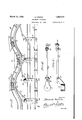
- v Figure 1 is a top plan view of an amusement apparatus constructed in accordance with the present invention showing the serpentine traekway over which the passenger boats travel and the areas adjacent thetrackway illustrating water;
- Figure 2 is a fragmentary side elevational view showing a light house rising centrally of the apparatus; 7
- Figure 3 is a fragmentary vertical longitudinal sectional view showing the serpentine track structure, the cable operated carriages and the connections between the carriages and passenger boats moving over the trackway;
- Figure 4 is a top plan view of the pivot block and link connection between the cable operated carriage and passenger boat;
- Figure 5 is a side elevational view of the link and block connection shown in Figure 4.
- FLgure 6 is a top plan view of the operating mechanism showing the motor driven gears for operating the endless cables;
- Figure 7 is a side elevational view of the apparatus shownin Figure 6;
- Figure 8 is a detail sectional View showing the track slots through which the link connections extend between the cable operated carriage and boat with the guide rails for the rollers or wheels of the carriage and boat;
- Figure 9 is a fragmentary rear elevational view of the passenger boat showing the pivotally supported rear axle to compensate Lin-evenness in track structure;
- Figure 10 is a top plan View of the frameor chassis for supporting the passenger boat body
- FIG 11 is a side elevational View of the passenger boat with the chassis frame attached thereto and with the track wheels and axles removed; and V Figure 12 shows perspective views of the lock washer and track axle.
- the amusement apparatus may be of any size, shape or design, but for the purpose or" illustration is shown as being of rectangular form having side walls 15 and end walls 16 and l7, the frame structure within the walls being provided with a platform with a portion thereoi constituting a pathway or walk 18 extending around the frame structure within and adjacent the walls thereof.
- the platform at opposite sides of the pathway 18 carries design configurations 19 and 20 representative of water or waves.
- An endless track structure 21 over which the boats 22 move is located within the design representation 26 and said platform within the track structure is designed as at 23 to'represent water with a lighthouse tower 24 rising centrally of the design area 23.
- Access to the amusement apparatus is gained by way of a stairway 25 at the end wail 17 that rises to the pathway 13, said pathway being bordered by guard rails 26 while access to the individual boat 22 is gained by way of the gang planks 27 as shown in Figure 1.
- the track 21 is of wavy or serpentine formation as shown in Figure 3 and said track is lengthwise slotted as at 28 for the passage of connecting devices extending between the boat 22 and the devices for moving the boats over the trackways.
- the passenger boat 22 carries sailrigging 29 and has a flat bottom for mounting upon the chassis frame shown. more clearly in Figures 3 to 12.
- the chassis frame 36 is bolted as at 31 to the underside of the hull of the boat 22 and carries transversely of its forward end a depending U-shaped bearing frame 32 in which the axle 33 is mounted for the support or" track wheels 34.
- Each end of the axle 33, as shown in Figure 12 is reduced and has an end socket 35 which receives a pin 36 carried by a washer 37 for locking the washer to the axle, the wheel 34 being retained on the end of the axle by means of the washer and screw 38.
- a U-shaped bearing 39 depends from the rear end of the chassis frame 30 and includes a pair of spaced lugs 40 so disposed to permit transverse pivotal movement of the rear axle 41 that is pivoted between the lugs 40 as at 42, each end of the axle 41 that is mounted for pivotal movement transversely of the chassis frame carrying a track wheel 34.
- the pivotal mounting of the axle 41 compensates for un-evenness in track structure and is also effective for producing a rolling motion of the boat 22 in addition to the pitching action thereof caused by the wavy or serpentine trackway 21.
- angle members 43 are secured to the trackway 21 in spaced relation at opposite sides of the track slots 28 and carryguard rails 44 overlying the track wheels 34, the angle mem bers and rails being positioned a sufficient distance apart relative to the chassis structure of the boat 22 to permit limited side or lateral movements of the boat during travel thereof over the trackway.
- the devices for moving the passenger boat 22 over the trackway 21 includes carriages having link connections with the boat and motor driven endless cables for moving the carriages, Figure 8 showing a floor or base board 45 disposed beneath the trackway 21 over which the carriages move.
- Each carriage comprises a pair of clamp plates 46 bolted together at 4'7 and carrying at their lower ends an axle 48 upon which wheels 49 are mounted for movement over the base board 45, angle members 50 secured to the base board 45 in spaced relation at opposite sides of the track slot 28 carrying guard rails 51 that overlie the carriage wheels 49.
- the upper ends of the clamp plates 46 carry a stud bearing 52 upon which the bearing block 53 shown in detail in Figures 4 and 5 is rotatably mounted and retained thereon by the washer device 54.
- the bearing block 53 carries a lateral upwardly and angularly directed arm 55 bifurcated at its upper free end as at 56 with the exception of one end of a link 57 that is pivotally retained therein as at 58.
- the other end of the link 57 extends upwardly through the slot 28 of the trackway and is pivotally connected as at 59 to a clevis 60 that is pivotally attached to the bearing 61 centrally depending from the chassis frame 30 as shown in Figures 3 and 11.
- the operating means for the carriages is located between the base board 45 and trackway 21 and as shown in Figures 3, 6 and '7, disks 62 and 63 of diameters substantially the same as the distance between opposite sides of the trackway are located respectively adjacent each end of the apparatus, being journalled on vertical bearing blocks 64.
- a relatively large gear wheel is made fast to the upper face of the disk 62, having a center bearing on the block 64 and said gear wheel 65 has meshing engagement with a relatively smaller gear wheel 66 journalled upon the upper end of the bearing post 67, the gear wheel 66 having meshing engagement with the pinion 68 fixed to the upper end of the motor shaft 69 of the electric motor '70 and is supported as illustrated in Figure 7.
- the contacting faces of the clamp plates 46 of each carriage are provided with mating grooves that receive and bind ingly engage endless cables 71, the cables and carriages forming an endless structure of a belt type moving around the disks 62 and 63.
- the driving connection for the carriages includes the provision of spaced recesses 72 in the peripheral edges of the disks 62 and 63 that take the clamp members 46, the disk 62 constituting the driving means for the cables 71 and clamp members 46.
- the link connections between the carriages and boat are of a character to compensate for the serpentine design of the trackway as shown in Figure 3, while the pivoted rear axle 41 upon the boat chassis frame 30 compensates for tin-evenness in track structure and also for permitting limited lateral or rolling motion of the passenger boat in addition to the shifting action created by the serpentine track structure.
- each carriage comprising a pair of perpendicular clamping plates, supporting rollers carried thereby, the carriage stud being located
Landscapes
- Chain Conveyers (AREA)
Description
March 27, 1934. H, 1,952,273
AMUSEMENT APPARATUS Filed June 11, 1932 4 Sheets-Sheet l k w i W a I M I PM. 3mm Q 5 Edmondo Mecchi x8 5% W R .4 Q WS March 27, 1934-. E, MECcHl 1,952,273
AMUSEMENT APPARATUS Filed June 11,-1932 4 eets-Sh e 2 Z'dmazvdo 77266072 i.
Sum/Mas March 27, 1934. E. MECCHI AMUSEMENT APPARATUS Filed June 11; 1932 4 Sheets-Sheet 3 March 27, 1934. E. MECCHI 1,952,273
AMUSEMENT APPARATUS Filed June 11. 1932 4 Sheets-Sheet 4 'I'drhofido mace/u.
Patented Mar. 27, 1934 AMUSEMENT APPARATUS Edmondo Mecchi, Brooklyn, N. Y.
Application June 11, 1932, Serial No. 616,718
3 Claims.
This invention relates to certain new and useful improvements in amusement apparatus.
The primary object of the invention is to provide amusement apparatus wherein passenger carriages, preferably in the form of boats are adapted to be motor driven and to travel in a circuitous path with means for imparting the pitching action during movement of the boat similar to the effect of a boat riding waves.
A further object of the invention is to provide amusement apparatus of the foregoing character wherein the serpentine track struo ture over vwhich passenger carrying boats move is disposed above a motor driven endless cable with track guided roller supported frames clampingly engaged with the cable and having operative connection with the boat for moving the boat over the serpentine track structure upon movement of the cable.
With the above and other objects in view that will become apparent as the nature of the invention is better understood, the same consists in the novel form, combination'and arrangement of parts hereinafter more fully described, shown in the accompanying drawings and claimed.
In the drawings:-
v Figure 1 is a top plan view of an amusement apparatus constructed in accordance with the present invention showing the serpentine traekway over which the passenger boats travel and the areas adjacent thetrackway illustrating water;
Figure 2 is a fragmentary side elevational view showing a light house rising centrally of the apparatus; 7
Figure 3 is a fragmentary vertical longitudinal sectional view showing the serpentine track structure, the cable operated carriages and the connections between the carriages and passenger boats moving over the trackway;
Figure 4 is a top plan view of the pivot block and link connection between the cable operated carriage and passenger boat;
Figure 5 is a side elevational view of the link and block connection shown in Figure 4;
FLgure 6 is a top plan view of the operating mechanism showing the motor driven gears for operating the endless cables;
Figure 7 is a side elevational view of the apparatus shownin Figure 6;
Figure 8 is a detail sectional View showing the track slots through which the link connections extend between the cable operated carriage and boat with the guide rails for the rollers or wheels of the carriage and boat;
Figure 9 is a fragmentary rear elevational view of the passenger boat showing the pivotally supported rear axle to compensate Lin-evenness in track structure; a
Figure 10 is a top plan View of the frameor chassis for supporting the passenger boat body;
Figure 11 is a side elevational View of the passenger boat with the chassis frame attached thereto and with the track wheels and axles removed; and V Figure 12 shows perspective views of the lock washer and track axle.
The amusement apparatus may be of any size, shape or design, but for the purpose or" illustration is shown as being of rectangular form having side walls 15 and end walls 16 and l7, the frame structure within the walls being provided with a platform with a portion thereoi constituting a pathway or walk 18 extending around the frame structure within and adjacent the walls thereof. The platform at opposite sides of the pathway 18 carries design configurations 19 and 20 representative of water or waves. An endless track structure 21 over which the boats 22 move is located within the design representation 26 and said platform within the track structure is designed as at 23 to'represent water with a lighthouse tower 24 rising centrally of the design area 23.
, Access to the amusement apparatus is gained by way of a stairway 25 at the end wail 17 that rises to the pathway 13, said pathway being bordered by guard rails 26 while access to the individual boat 22 is gained by way of the gang planks 27 as shown in Figure 1.
The track 21 is of wavy or serpentine formation as shown in Figure 3 and said track is lengthwise slotted as at 28 for the passage of connecting devices extending between the boat 22 and the devices for moving the boats over the trackways.
The passenger boat 22 carries sailrigging 29 and has a flat bottom for mounting upon the chassis frame shown. more clearly in Figures 3 to 12. The chassis frame 36 is bolted as at 31 to the underside of the hull of the boat 22 and carries transversely of its forward end a depending U-shaped bearing frame 32 in which the axle 33 is mounted for the support or" track wheels 34. Each end of the axle 33, as shown in Figure 12 is reduced and has an end socket 35 which receives a pin 36 carried by a washer 37 for locking the washer to the axle, the wheel 34 being retained on the end of the axle by means of the washer and screw 38. A U-shaped bearing 39 depends from the rear end of the chassis frame 30 and includes a pair of spaced lugs 40 so disposed to permit transverse pivotal movement of the rear axle 41 that is pivoted between the lugs 40 as at 42, each end of the axle 41 that is mounted for pivotal movement transversely of the chassis frame carrying a track wheel 34. The pivotal mounting of the axle 41 compensates for un-evenness in track structure and is also effective for producing a rolling motion of the boat 22 in addition to the pitching action thereof caused by the wavy or serpentine trackway 21. As shown in Figures 3 and 8, angle members 43 are secured to the trackway 21 in spaced relation at opposite sides of the track slots 28 and carryguard rails 44 overlying the track wheels 34, the angle mem bers and rails being positioned a sufficient distance apart relative to the chassis structure of the boat 22 to permit limited side or lateral movements of the boat during travel thereof over the trackway.
The devices for moving the passenger boat 22 over the trackway 21 includes carriages having link connections with the boat and motor driven endless cables for moving the carriages, Figure 8 showing a floor or base board 45 disposed beneath the trackway 21 over which the carriages move. Each carriage comprises a pair of clamp plates 46 bolted together at 4'7 and carrying at their lower ends an axle 48 upon which wheels 49 are mounted for movement over the base board 45, angle members 50 secured to the base board 45 in spaced relation at opposite sides of the track slot 28 carrying guard rails 51 that overlie the carriage wheels 49. The upper ends of the clamp plates 46 carry a stud bearing 52 upon which the bearing block 53 shown in detail in Figures 4 and 5 is rotatably mounted and retained thereon by the washer device 54. The bearing block 53 carries a lateral upwardly and angularly directed arm 55 bifurcated at its upper free end as at 56 with the exception of one end of a link 57 that is pivotally retained therein as at 58. The other end of the link 57 extends upwardly through the slot 28 of the trackway and is pivotally connected as at 59 to a clevis 60 that is pivotally attached to the bearing 61 centrally depending from the chassis frame 30 as shown in Figures 3 and 11.
The operating means for the carriages is located between the base board 45 and trackway 21 and as shown in Figures 3, 6 and '7, disks 62 and 63 of diameters substantially the same as the distance between opposite sides of the trackway are located respectively adjacent each end of the apparatus, being journalled on vertical bearing blocks 64. A relatively large gear wheel is made fast to the upper face of the disk 62, having a center bearing on the block 64 and said gear wheel 65 has meshing engagement with a relatively smaller gear wheel 66 journalled upon the upper end of the bearing post 67, the gear wheel 66 having meshing engagement with the pinion 68 fixed to the upper end of the motor shaft 69 of the electric motor '70 and is supported as illustrated in Figure 7. The contacting faces of the clamp plates 46 of each carriage are provided with mating grooves that receive and bind ingly engage endless cables 71, the cables and carriages forming an endless structure of a belt type moving around the disks 62 and 63. The
carriages are maintained in spaced relation on the endless cables 71 by their clamped engagement with the cables and the passenger boats 22 are similarly maintained in spaced relation. The driving connection for the carriages includes the provision of spaced recesses 72 in the peripheral edges of the disks 62 and 63 that take the clamp members 46, the disk 62 constituting the driving means for the cables 71 and clamp members 46.
From the above detailed description of the invention, it is believed that the construction and operation thereof will at once be apparent, it being noted that upon rotation of the disk 62 by its gear train connection with the electric motor 70, the endless cables '71 and clamp members 46 of the carriages move around the disks 62 and 63 with the clamp members being received in the disk notches '72 to be propelled by the disks, the link connections between the carriages and passenger boat causing the boat to move over the trackway 21. The link connections between the carriages and boat are of a character to compensate for the serpentine design of the trackway as shown in Figure 3, while the pivoted rear axle 41 upon the boat chassis frame 30 compensates for tin-evenness in track structure and also for permitting limited lateral or rolling motion of the passenger boat in addition to the shifting action created by the serpentine track structure. While there is herein shown and described the preferred embodiment of the invention, it is nevertheless to be understood that minor changes may be made therein without departing from the spirit and scope of the invention as claimed.
I claim:
1. In amusement apparatus, wherein passenger boats are movable over a slotted track and wherein carriages are movable beneath the track, a link connection between a carriage and a boat including a stud rising from the carriage, and a stud depending from the boat, a clevis pivoted on each stud and a link connection between the clevises extending through the track slot.
2. In amusement apparatus, wherein. passenger boats are movable over a slotted track and wherein carriages are movable beneath the track, a link connection between a carriage and a boat including a stud rising from the carriage, and a stud depending from the boat, a clevis pivoted on each stud and a link connection between the clevises extending through the track slot, each carriage comprising a pair of clamping plates and driving cables clamped between the plates.
3. In amusement apparatus, wherein passenger boats are movable over a slotted track and wherein carriages are movable beneath the track, a link connection between a carriage and a boat including a stud rising from the carriage,
and a stud depending from the boat, a clevis pivoted on each stud and a link connection be tween the clevises extending through the track slot, each carriage comprising a pair of perpendicular clamping plates, supporting rollers carried thereby, the carriage stud being located
Priority Applications (1)
| Application Number | Priority Date | Filing Date | Title |
|---|---|---|---|
| US616718A US1952273A (en) | 1932-06-11 | 1932-06-11 | Amusement apparatus |
Applications Claiming Priority (1)
| Application Number | Priority Date | Filing Date | Title |
|---|---|---|---|
| US616718A US1952273A (en) | 1932-06-11 | 1932-06-11 | Amusement apparatus |
Publications (1)
| Publication Number | Publication Date |
|---|---|
| US1952273A true US1952273A (en) | 1934-03-27 |
Family
ID=24470680
Family Applications (1)
| Application Number | Title | Priority Date | Filing Date |
|---|---|---|---|
| US616718A Expired - Lifetime US1952273A (en) | 1932-06-11 | 1932-06-11 | Amusement apparatus |
Country Status (1)
| Country | Link |
|---|---|
| US (1) | US1952273A (en) |
-
1932
- 1932-06-11 US US616718A patent/US1952273A/en not_active Expired - Lifetime
Similar Documents
| Publication | Publication Date | Title |
|---|---|---|
| US3981612A (en) | Wave Producing apparatus | |
| JPH0479673B2 (en) | ||
| US2009904A (en) | Vehicle | |
| US2229015A (en) | Rail tractor or like haulage unit | |
| US1952273A (en) | Amusement apparatus | |
| JP2002273063A (en) | Ferris wheel | |
| US5061211A (en) | Amphibian air car | |
| JP3439202B2 (en) | Ferris wheel | |
| CN108032959B (en) | Running gear and adopt this running gear's multi-functional automatic mounting plate of trackless | |
| US2700345A (en) | Elevated railways and traction means therefor | |
| US1541589A (en) | Monorail system | |
| US3155246A (en) | Parking equipment | |
| US3057487A (en) | Automobile parking system | |
| US1773636A (en) | Driving mechanism for amusement devices | |
| CN114889653A (en) | Cable transportation system | |
| KR102260564B1 (en) | turnout apparatus for monorail railway | |
| US2220704A (en) | Overhead welding gantry | |
| JP3489716B2 (en) | Structure consisting of Ferris wheel and elevated vehicle | |
| US1924833A (en) | Brake testing apparatus | |
| US1370385A (en) | Amusement device | |
| JP3578849B2 (en) | Derailment track land vehicle return transfer tool | |
| JPH04361777A (en) | Vehicle for aquatic amusement | |
| US1487274A (en) | Amusement device | |
| SU944980A1 (en) | Apparatus for assembling a module of ship hull middle part | |
| US1838227A (en) | Truck for amusement cars |