US1941237A - Hand telephone - Google Patents
Hand telephone Download PDFInfo
- Publication number
- US1941237A US1941237A US521894A US52189431A US1941237A US 1941237 A US1941237 A US 1941237A US 521894 A US521894 A US 521894A US 52189431 A US52189431 A US 52189431A US 1941237 A US1941237 A US 1941237A
- Authority
- US
- United States
- Prior art keywords
- handset
- dial
- hand
- telephone
- microphone
- Prior art date
- Legal status (The legal status is an assumption and is not a legal conclusion. Google has not performed a legal analysis and makes no representation as to the accuracy of the status listed.)
- Expired - Lifetime
Links
- 238000010276 construction Methods 0.000 description 6
- NJPPVKZQTLUDBO-UHFFFAOYSA-N novaluron Chemical compound C1=C(Cl)C(OC(F)(F)C(OC(F)(F)F)F)=CC=C1NC(=O)NC(=O)C1=C(F)C=CC=C1F NJPPVKZQTLUDBO-UHFFFAOYSA-N 0.000 description 4
- 230000002349 favourable effect Effects 0.000 description 2
- 230000000994 depressogenic effect Effects 0.000 description 1
- 239000000428 dust Substances 0.000 description 1
- 239000000463 material Substances 0.000 description 1
- 238000012986 modification Methods 0.000 description 1
- 230000004048 modification Effects 0.000 description 1
- QVRVXSZKCXFBTE-UHFFFAOYSA-N n-[4-(6,7-dimethoxy-3,4-dihydro-1h-isoquinolin-2-yl)butyl]-2-(2-fluoroethoxy)-5-methylbenzamide Chemical compound C1C=2C=C(OC)C(OC)=CC=2CCN1CCCCNC(=O)C1=CC(C)=CC=C1OCCF QVRVXSZKCXFBTE-UHFFFAOYSA-N 0.000 description 1
Images


Classifications
-
- H—ELECTRICITY
- H04—ELECTRIC COMMUNICATION TECHNIQUE
- H04M—TELEPHONIC COMMUNICATION
- H04M1/00—Substation equipment, e.g. for use by subscribers
- H04M1/02—Constructional features of telephone sets
- H04M1/0202—Portable telephone sets, e.g. cordless phones, mobile phones or bar type handsets
Definitions
- the telephone table instruments with automatic operation, normally used may be divided of instrument has the disadvantage that, in
- the combined microphone and telephone such as used in a hand set is of advantage to the user.
- the pillar instrument has also the advantage'that thev standing place of the. instrument isof no consequence to the user with regard to theoperation of the dial as the instrument'is taken in the hand for speaking purposes but has. the great drawback that both hands must be used for holding the instrument when speaking as the 3 telephone is not fixed to the apparatus. If, on
- the dial for this purpose is located near the microphone mouthpiece onthe side of the ear cap, inside a space limited by the plane of the ear cap.
- This arrangement of the dial and corresponding design of the casing body makes it possible to hold the handset, while in its normal position, in a comfortable grip and bring it into the-service position for dialling and later into the I speaking positionin an easyandnatural manner Without a change ofvgrip or unpleasant twisting of the handsbeing necessary.
- the handset is hereby improved, with; regard to its equalized, weight and thus offers a particularly easy and comfortable handling.
- this arrangement consists in that'the length of 35 the handset can be limited to a minimum with the result that the weight of the instrument is increased only a little.
- handling of such an instrument is alsomore pleasant and the'cost of production favourably 1 influenced.
- H One embodimentof the invention is shown in the drawings in various, viewsand more completely' described in the following:
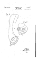
- Fig. 1 shows a handset-in side view-and part 7 of the invention
- Fig.5" shows a sectionof the handset in Fig. 4 according to-line C-D.. I
- Figs. 6 and 7 are side views of still further modifications of construction. I
- the numeral 1 represents the body' of the handset and 2 the ear cap of the telephone,
- the casing body 1 forms a well 3 in its lower end
- the casing body 1 at the part which forms the mouthpiece for the microphone, is provided with holes '7 as an entrance for the sound waves.
- the lower hollow in the handset is. terminated by the dial 8.
- the casing 3 for the dial 8, in addition to the microphone unit 4 and terminals 5, contains the calling key.
- the latter .consists of a set of contact springs 10 and the switch pin 11', actuating them, which is so arranged thatit is permanently depressed as long as the handset rests in its normal position and thus an automatic switching operation is achieved.
- the key and the associated switch member can also, of course, be fitted in the upper casing 2, e. g., in the case of a suspended normal position of the handset. 1 0
- the lower portion of the handle 12 broadens toward the bottom and forms a casing 13 provided with a mouth-piece for the microphone and dial switch.
- the lower opening of the casing 13 is entirely closed by the supporting surface, for example, the table on which it stands so that at the same time, dust is prevented from settling on the dial.
- the lower part differs in construction from that of Fig. 6 in that the dial switch in this case is in the relation to the set as in the construction shown in Fig. l.
- the arrangement offers a particularly comfortable handling, but requires a different construction of the lower casing body in order to obtain a supporting surface.
- a projection 16 is provided at the lower part of the casing body 12 which, together with the flattened portion of the casing 13, furnishes the necessary supporting surface for the handset.
- a handset of such design can be associated with a special base plinth 17, as shown, which forms the support for the handset in its normal position.
- This base plinth can be covered with felt or the like so that the supporting points for the handset need not be damaged by the careless replacement of the handset.
- the base plinth 17 can also be fitted to receive theconnecting cord.
- the microphone and dial are located in a constricted arrangement in a space to the right of line AB drawn through the plane of the ear cap.
- the re sult of this arrangement is that, in contrast to such designs of handsets with dial, in which the r latter is located on the back of the handset orin other arrangementson the front of the upper part of the handset and penetrates into the bordering line AB, operation is very much facilitated.
- a turning round of the handset is necessary in order to dial, which is an unwanted exertion. If the dial, as mentioned, is located in the upper part of the front of the handset it is in the way for the user in the listening position due to its location at the ear cap.
- the dial is located in the upper part of the front of the handset it is in the way for the user in the listening position due to its location at the ear cap.
- the dial receives such a favourable position, as will be seen by the embodiment, that a particularly comfortable operation of the dial is achieved without the handset having to be brought into any one special position.
- a base portion for supporting the hand telephone in an upright position, and an impulse transmitting device in the space surrounded by the material of said pedestal constituting the base portion.
- a base portion for supporting the hand telephone in an upright position, a microphone cell and an impulse transmitting device, respectively, mounted inside the base portion thereof.
- a handle having an upper portion arranged to receive a receiver. unit and having its lower portion bell shaped to form a casing for a microphone unit and impulse transmitting device, said bell-shaped portion also serving as a base for holding the hand tele-' phone in an upright position when not in use.
- a unitary structure comprising a pedestal type hand telephone having a receiver and microphone cell mounted therein, a base for supporting the hand telephone in an upright position, and an impulse transmitting device'lying in a plane at substantially right angles to the receiver normally hidden from view by said base.
- a hand portion serving as a casing, a receiver mounted on one end thereof, an opening in the other end, a transmitter mounted in said opening, an impulse sender mounted in the same opening over the transmitter and closing said opening, and another opening in the hand portion adjacent the transmitter.
- OTTO WEEBER OTTO SOLDAN.
Landscapes
- Engineering & Computer Science (AREA)
- Signal Processing (AREA)
- Telephone Set Structure (AREA)
Applications Claiming Priority (1)
| Application Number | Priority Date | Filing Date | Title |
|---|---|---|---|
| DE612628T | 1930-06-08 |
Publications (1)
| Publication Number | Publication Date |
|---|---|
| US1941237A true US1941237A (en) | 1933-12-26 |
Family
ID=34812886
Family Applications (1)
| Application Number | Title | Priority Date | Filing Date |
|---|---|---|---|
| US521894A Expired - Lifetime US1941237A (en) | 1930-06-08 | 1931-03-12 | Hand telephone |
Country Status (3)
| Country | Link |
|---|---|
| US (1) | US1941237A (fr) |
| DE (2) | DE612628C (fr) |
| FR (1) | FR718324A (fr) |
Cited By (3)
| Publication number | Priority date | Publication date | Assignee | Title |
|---|---|---|---|---|
| US2419388A (en) * | 1941-07-10 | 1947-04-22 | Ericsson Telefon Ab L M | Telephone handset |
| US2506715A (en) * | 1947-08-22 | 1950-05-09 | Automatic Elect Lab | Loud-speaking telephone station set with separate acoustic passages to the receiver and transmitter |
| US2822432A (en) * | 1951-01-25 | 1958-02-04 | Ericsson Telefon Ab L M | Casing for telephone instruments |
Families Citing this family (2)
| Publication number | Priority date | Publication date | Assignee | Title |
|---|---|---|---|---|
| US2490637A (en) * | 1944-04-06 | 1949-12-06 | Ericsson Telefon Ab L M | Handset provided with a sound collecting lid movably mounted before the microphone |
| FR2415394A1 (fr) * | 1978-01-24 | 1979-08-17 | Lepoix Louis | Telephone a commutation manuelle |
-
1930
- 1930-06-08 DE DE1930612628D patent/DE612628C/de not_active Expired
- 1930-07-20 DE DE1930621185D patent/DE621185C/de not_active Expired
-
1931
- 1931-03-12 US US521894A patent/US1941237A/en not_active Expired - Lifetime
- 1931-06-06 FR FR718324D patent/FR718324A/fr not_active Expired
Cited By (3)
| Publication number | Priority date | Publication date | Assignee | Title |
|---|---|---|---|---|
| US2419388A (en) * | 1941-07-10 | 1947-04-22 | Ericsson Telefon Ab L M | Telephone handset |
| US2506715A (en) * | 1947-08-22 | 1950-05-09 | Automatic Elect Lab | Loud-speaking telephone station set with separate acoustic passages to the receiver and transmitter |
| US2822432A (en) * | 1951-01-25 | 1958-02-04 | Ericsson Telefon Ab L M | Casing for telephone instruments |
Also Published As
| Publication number | Publication date |
|---|---|
| DE621185C (de) | 1935-11-06 |
| FR718324A (fr) | 1932-01-23 |
| DE612628C (de) | 1935-04-30 |
Similar Documents
| Publication | Publication Date | Title |
|---|---|---|
| US7286860B2 (en) | Systems and methods for a comfortable wireless communication device | |
| JPH1188483A (ja) | 簡易型携帯電話機 | |
| US2419388A (en) | Telephone handset | |
| US1941237A (en) | Hand telephone | |
| US3384718A (en) | Telephone handset housing | |
| US3483333A (en) | Telephone subscriber set | |
| US6009169A (en) | Inmate phone | |
| US2405543A (en) | Telephone set | |
| USRE26034E (en) | Telephone subset | |
| US3707607A (en) | Hands-free emergency call box | |
| US2410434A (en) | Telephone | |
| GB2087686A (en) | One piece telephones | |
| NO171440B (no) | Mikrotelefon | |
| US2392321A (en) | Desk telephone set | |
| US2657265A (en) | Amplifying device for use with telephone apparatus | |
| NO811274L (no) | Betjeningsapparat for mobilradio. | |
| KR200493095Y1 (ko) | 전화통화 수신음성 문자표시기 | |
| US2485574A (en) | Telephone handset | |
| US3011024A (en) | Telephone set | |
| US925775A (en) | Appliance for use with telephone-transmitters. | |
| US961157A (en) | Telephone attachment. | |
| US2100887A (en) | Interior telephone equipment | |
| US4410771A (en) | Telephone handset receptacle for off-hook placement | |
| US897084A (en) | Appliance for use with telephone-transmitters. | |
| US232159A (en) | Telephone-switch |