US192937A - Improvement in double-acting pumps - Google Patents
Improvement in double-acting pumps Download PDFInfo
- Publication number
- US192937A US192937A US192937DA US192937A US 192937 A US192937 A US 192937A US 192937D A US192937D A US 192937DA US 192937 A US192937 A US 192937A
- Authority
- US
- United States
- Prior art keywords
- valve
- pump
- piston
- chamber
- passage
- Prior art date
- Legal status (The legal status is an assumption and is not a legal conclusion. Google has not performed a legal analysis and makes no representation as to the accuracy of the status listed.)
- Expired - Lifetime
Links
- 238000010276 construction Methods 0.000 description 8
- 238000012856 packing Methods 0.000 description 5
- XLYOFNOQVPJJNP-UHFFFAOYSA-N water Substances O XLYOFNOQVPJJNP-UHFFFAOYSA-N 0.000 description 5
- 239000010985 leather Substances 0.000 description 3
- 239000000463 material Substances 0.000 description 3
- 238000000034 method Methods 0.000 description 3
- 239000002184 metal Substances 0.000 description 2
- 241000252206 Cypriniformes Species 0.000 description 1
- 240000001973 Ficus microcarpa Species 0.000 description 1
- LGDAGYXJBDILKZ-UHFFFAOYSA-N [2-methyl-1,1-dioxo-3-(pyridin-2-ylcarbamoyl)-1$l^{6},2-benzothiazin-4-yl] 2,2-dimethylpropanoate Chemical compound CC(C)(C)C(=O)OC=1C2=CC=CC=C2S(=O)(=O)N(C)C=1C(=O)NC1=CC=CC=N1 LGDAGYXJBDILKZ-UHFFFAOYSA-N 0.000 description 1
- 230000007547 defect Effects 0.000 description 1
- 230000000630 rising effect Effects 0.000 description 1
Images


Classifications
-
- F—MECHANICAL ENGINEERING; LIGHTING; HEATING; WEAPONS; BLASTING
- F04—POSITIVE - DISPLACEMENT MACHINES FOR LIQUIDS; PUMPS FOR LIQUIDS OR ELASTIC FLUIDS
- F04B—POSITIVE-DISPLACEMENT MACHINES FOR LIQUIDS; PUMPS
- F04B53/00—Component parts, details or accessories not provided for in, or of interest apart from, groups F04B1/00 - F04B23/00 or F04B39/00 - F04B47/00
Definitions
- Patented J'u1y10,11877 Patented J'u1y10,11877.
- My invention relates to improvements upon a pump Letters Patent for which wereA granted to me, dated September l, 187 4, and numbered 154,566, saidv patent being for an improvement in double-acting pumps, plicable to ships pumps, but also applicable to draining mines, and for other purposes.
- the object of my' present invention is to render said pump more efficient for use as a ships pump, and for other purposes, by reildering it less liable to choke, by making the of valves ⁇ more easily accessifacilitating the operation of sounding through the pump, and by such changes in the construction of parts as will enable the pump to be worked with less power, and render the pump generally more serviceable.
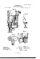
- FIG. 1 in the accompanying drawings is a side elevation of a pump comprising my immore especially approvements.
- Fig. 2 is a top view of the same.
- Fig. 3 is a sectional elevation, the vertical section being on the line a: :i: in Fig. 2.
- Fig. 4 is a horizontal sectiony on the line z zin Fig.
- Fig. 5 is a vertical section on. the line y y in Fig. 2.
- Fig. 7 is a detail view of two connected detachable valves and their connection.
- Fig. 8 is a detail vertical section on the line 'u v in Fig. 2.
- A is the suction-pipe, separated from the lower valvechambei" B by a valve, C.
- a passage, D leads to the ⁇ upper valve-chamber E, from which itis separated by a valve, F.
- G From the lower valve-chamber B a passage, G, leads into the lower part of the piston-chamber H, and from the upper valvey(meunier E a passage, I, leads into 'the upper part 4of the said piston-chamber H.
- the upper' end of the lower valve-chamber 'B is closed by' a valve, J, from which a passage K, leads 'to the head L of the pump.l
- the upper end of the upper valve-chamber E ⁇ is closed by a plate, M, which is held down to its seat by a screw, N, which passes through a screw-hole in the barO, the ends of which are placed beneath lugs P, cast upon the head L.
- Q is the piston, the rod R of ⁇ which passes upV through the valve S, which rests upon the upper end of the piston-chamber H, and serves as a discharge-valve to said chamber.
- the ⁇ pistonrod R is reciprocated by any suitable means, and the pump operates as follows:
- valves O and J were puppet or drop valves, independently-inserted, and requiring separate removal for sounding the pump, which sounding was and now'is done, after removing said valves, through the straight (and after removal of the valves) continuous passage L K B A.
- An improvement upon that construction, which constitutes one feature of my present invention, is a novel connection of said valves together in such manner'that they may be simultaneously inserted into or removed from the pumpba'rre'l, and novel means for securely holding i said valves in the pump-barrel, which at the 4 tion is shown in Figs. 2, 5, 6, and 7.
- valve J and its guide k, Figs. 5 and 7, are attached to a clamping and lifting bar, T, preferably formed in one piece with the guide k.
- a lifting-bar, T', Figs. 5 and 7, also preferably formed in one piece with the clamping and lifting bar T and guide 7c; but the said parts T, T', and k may be separately formed, and afterward conjoined, by any suitable means.
- a bolt, a which also passes down through the valve C.
- Said bolt a is fitted loosely in the end of the liftingbar T', and acts partly as a stem for the valve G.
- the upper end of the clamping and lifting bar T is beveled or inclined, as shown at o, Figs. 5 vand 7, to fit under a lug, d, Fig. 5, when the said bar and the attached valves are placed in the pump.
- To the upper part of the clamping and lifting bar T is pivoted a clamping cross-bar, f, Figs. 5 and 7, which, when placed within the pump-barrel in the position shown in Fig.
- valve-seats when the valves are placed in the pump-barrel, are respectively formed upon shoulders g and h, Fig. 5, formed in the pump-barrel.
- the clamping cross-bar f is pulled upward into the position shown in dotted outline in Fig. 5, the clamping and lifting bar is pushed out from under the lug d, and the said clamping and lifting bar T, valve J, valve-guide lo, lifting-bar T', bolt a, and valve G are all together lifted out of the pumpbarrel.
- the said valves are replaced by putting all the parts so lifted out together back in the pump-barrel, crowding the beveled end of the clamping and lifting bar T under the lug d, and pressing the clamping cross-bar f down against the inner wall of the pump-barrel, as shown in full outline in Fig. 5.
- Another improvement on the original invention consists in the novel construction of and novel method of inserting the valve S in the head of the pump, to cover the top of the piston-chamber H.
- said valve S was a at plate, and had the piston-rod R passed through its center, serving as a guide forsaid valve.
- the said valve in order to have the requisite free play, had to be loosely fitted Vto said piston-rod, such loose tting permitting leakage of air into and impairing the efficiency of the pump.
- valve In the present invention I fit the valve to the piston-rod in such manner that it is practically air-tight around the piston yet it retains all the necessary freedom of motion on the piston-rod.
- valve S may be a centrally-perforated disk or a double flap-valve, made of metal plates attached to a perforated piece of leather, rubber, or other suitable flexible material, or it may be a metal plate packed around said piston-rod, as hereinafter described, and carrying puppet or drop valves; but whatever may be the material or construction of the valve, the method of inserting and holding it in the pump, and packing it around the piston-rod, forming features -of the present invention, are the same, and they will be sufficiently illustrated by the description of the same, as when a double flap-valve is used.
- the valve S is, by bolts or otherwise, attached to the under side of the horizontal part of the said yoke-guide fn, which thus forms a support for said valve, thel seat of the valve being on the 'shoulder 0,1 Figs. 5 and 8, at the top of the piston-chamber H.
- the parts of the valve S lying, respectively, on opposite sides of ,the horizontal part of the yoke n, act together as a double ap-valve.
- the weight of the yoke-guide n is sufficient to hold the valve S in place; but pins may be used, if desired, for this purpose.
- an upturned packing, p, Figs. 2, 5, and 8 to pack the central perforation in said valve, and its supporting-yoke 'n around the piston-rod R; and of a separate piece of similar materialIform a turned-down cup-packing, p', for the same purpose, said packings being interposed and held between the horizontal part of the yoke-guide n and a plate, r, Figs. 5 and 8, bolted or otherwise attached to the said yoke-guide; but the said valve may be packed around the piston-rod in other ways.
- valve F in the chamber E was a simple clapper-valve, which required a special appliance for its removal, in order to open and clear out the passage D after the removal of the plate M, which tightly. closes the top of the said chamber, as hereinbefore described.
- my present invention employ, as animprovement over the former construction, 'a combined double ap and puppet valve, F, which seats on a shoulder, s, Fig. 3, at the top of the passage D.
- the flaps j" f', Figs. 3 and 4, of said valve are hinged to a central T-shaped stem, t, which is fitted loosely in a sleeve, a', Fig. 3, that projects downward from the plate M.
- Said stem t and sleeve a form guides for said valve F, said valve acting under ordinary circumstances as a dapvalve; but when any oating obstruction too large to pass easily through the valve reaches said valve, the whole valve and the stem t rise bodily to permit the passage of such obstruction by and through said valve, and thus prevent'choking of said valve.
- the stem t acts as a convenient handle for lifting out 'the valve F when it is desired to open the passage D.
- the valve C is constructed in like manner, to act both as a double flap and puppet valve, the bolt a acting ,as a stem for said valve, playing vertically in th'e perforated end of the lifting-bar T'.
- valve S having the valve S attached to it, and acting as a guide both for said valve and the pistonrod R, with the vertical guides m, provided inside of the head L of the pump, and itted to the vertical parts of said yoke-guide, substantially as and for the purpose described.
Landscapes
- Engineering & Computer Science (AREA)
- Mechanical Engineering (AREA)
- General Engineering & Computer Science (AREA)
- Details Of Reciprocating Pumps (AREA)
Description
` 2 She ets-S11 e ei 1.
."LRoBERTso'N. DOUBLE-ACTING' PUMP.
No. 192,937. Patented Juv1y,1 o,1e7n7.
MPETERS, PHoTo unicam z sheets-sheen.
J. RoBERTsoN. DOUBLE-ACTING PUMP.
Patented J'u1y10,11877.
figa;
NPEERS, PHOTO-4. THOGRAFHER, WASHINGTON D C Brooklyn, :of New York, have inventedan improvement 1n Pumps 5 and I do hereby declare that the working parts ble by PATENT OFFICE.
J ROBERTSON, OF
BROOKLYN, NEW YORK.
IMPROVEMENT lIN VDOUBLE-'ACTING PUMPS.
Specification forming part of Letters Patent No. 192,937-, dated July 10,?1877 application led June 18, 1877.
To all whom it may concern: 1 Be itknown that I, JAMES ROBERTSON, of in the county of Kings and State following is a full, clear, and exact description of the same, reference being had to the accompanying drawings, forming part of this specification. v
My invention relates to improvements upon a pump Letters Patent for which wereA granted to me, dated September l, 187 4, and numbered 154,566, saidv patent being for an improvement in double-acting pumps, plicable to ships pumps, but also applicable to draining mines, and for other purposes.
The object of my' present invention is to render said pump more efficient for use as a ships pump, and for other purposes, by reildering it less liable to choke, by making the of valves `more easily accessifacilitating the operation of sounding through the pump, and by such changes in the construction of parts as will enable the pump to be worked with less power, and render the pump generally more serviceable.
'Figure 1 in the accompanying drawings is a side elevation of a pump comprising my immore especially approvements. Fig. 2 is a top view of the same.
Fig. 3 is a sectional elevation, the vertical section being on the line a: :i: in Fig. 2. Fig. 4 is a horizontal sectiony on the line z zin Fig.
Fig. 5 isa vertical section on. the line y y in Fig. 2. Fig. Gis achorizjontal section on the line 'w w in Fig. l. Fig. 7 is a detail view of two connected detachable valves and their connection. Fig. 8 is a detail vertical section on the line 'u v in Fig. 2.
The general construction of the pump, as
l.originally constructed, is as follows z. A is the suction-pipe, separated from the lower valvechambei" B by a valve, C. From the tube A a passage, D, leads to the `upper valve-chamber E, from which itis separated by a valve, F. From the lower valve-chamber B a passage, G, leads into the lower part of the piston-chamber H, and from the upper valvey(meunier E a passage, I, leads into 'the upper part 4of the said piston-chamber H. The upper' end of the lower valve-chamber 'B is closed by' a valve, J, from which a passage K, leads 'to the head L of the pump.l The upper end of the upper valve-chamber E` is closed by a plate, M, which is held down to its seat by a screw, N, which passes through a screw-hole in the barO, the ends of which are placed beneath lugs P, cast upon the head L. Q is the piston, the rod R of` which passes upV through the valve S, which rests upon the upper end of the piston-chamber H, and serves as a discharge-valve to said chamber. The `pistonrod R is reciprocated by any suitable means, and the pump operates as follows:
As the piston Q rises, water passes up through the pipe A, raisesthe valve O, passes into the chamber B, and thence through the passage Gr into the piston-chamber H, under the piston Q, whence it is forced out by the next downward stroke of the piston. While rising thepiston Q also lifts the water which lies above it out of the piston-chamber H, through the valve S, into the head L of the pump, whence it ows out .through a spout, B. The downward stroke of the piston Q forces the water out of thechamber H from below said piston, through the chamber B, up through the valve Jy and passage K, into the head of the pump L. At the same time the valve S closes, and a vacuum is produced in' the space above the piston, below said valve S and in the chamber E, communicating with said space by the passage I. To ill this vacuum, water rises through the pipe A, passage D, and valve F, said water being lifted by the next upstroke of the piston Q, through: the valve S, into the head L, whence it flows out through the spout B. l
`In my former invention, of vwhich the general features of construction and operation are above described, the valves O and J were puppet or drop valves, independently-inserted, and requiring separate removal for sounding the pump, which sounding was and now'is done, after removing said valves, through the straight (and after removal of the valves) continuous passage L K B A. An improvement upon that construction, which constitutes one feature of my present invention, is a novel connection of said valves together in such manner'that they may be simultaneously inserted into or removed from the pumpba'rre'l, and novel means for securely holding i said valves in the pump-barrel, which at the 4 tion is shown in Figs. 2, 5, 6, and 7.
The valve J and its guide k, Figs. 5 and 7, are attached to a clamping and lifting bar, T, preferably formed in one piece with the guide k. Below said guide 7c projects downward and inwardly a lifting-bar, T', Figs. 5 and 7, also preferably formed in one piece with the clamping and lifting bar T and guide 7c; but the said parts T, T', and k may be separately formed, and afterward conjoined, by any suitable means.
Through the lower end of the lifting-bar T', I pass a bolt, a, which also passes down through the valve C. Said bolt a is fitted loosely in the end of the liftingbar T', and acts partly as a stem for the valve G. The upper end of the clamping and lifting bar T is beveled or inclined, as shown at o, Figs. 5 vand 7, to fit under a lug, d, Fig. 5, when the said bar and the attached valves are placed in the pump. To the upper part of the clamping and lifting bar T is pivoted a clamping cross-bar, f, Figs. 5 and 7, which, when placed within the pump-barrel in the position shown in Fig. 5, and pressed down against the side of the barrel, firmly presses and clamps thebar T against the opposite side of said barrel. The valve-seats, when the valves are placed in the pump-barrel, are respectively formed upon shoulders g and h, Fig. 5, formed in the pump-barrel.
This construction permits great rapidity in taking out or putting in the valves J and C.
- To take them out the clamping cross-bar f is pulled upward into the position shown in dotted outline in Fig. 5, the clamping and lifting bar is pushed out from under the lug d, and the said clamping and lifting bar T, valve J, valve-guide lo, lifting-bar T', bolt a, and valve G are all together lifted out of the pumpbarrel. The said valves are replaced by putting all the parts so lifted out together back in the pump-barrel, crowding the beveled end of the clamping and lifting bar T under the lug d, and pressing the clamping cross-bar f down against the inner wall of the pump-barrel, as shown in full outline in Fig. 5.
Another improvement on the original invention consists in the novel construction of and novel method of inserting the valve S in the head of the pump, to cover the top of the piston-chamber H.
In the invention for which the Letters Patent above referred to were granted to me,
' said valve S was a at plate, and had the piston-rod R passed through its center, serving as a guide forsaid valve. In this method of constructionjthe said valve, in order to have the requisite free play, had to be loosely fitted Vto said piston-rod, such loose tting permitting leakage of air into and impairing the efficiency of the pump.
In the present invention I fit the valve to the piston-rod in such manner that it is practically air-tight around the piston yet it retains all the necessary freedom of motion on the piston-rod.
Said valve S may be a centrally-perforated disk or a double flap-valve, made of metal plates attached to a perforated piece of leather, rubber, or other suitable flexible material, or it may be a metal plate packed around said piston-rod, as hereinafter described, and carrying puppet or drop valves; but whatever may be the material or construction of the valve, the method of inserting and holding it in the pump, and packing it around the piston-rod, forming features -of the present invention, are the same, and they will be sufficiently illustrated by the description of the same, as when a double flap-valve is used.
On the interior of the head L of ythe pump are formed vertical guides m, Figs. 2 and 8. To said guides is tted the` yoke-guide n for the piston-rod R, the vertical portions of said yoke-guide being externally grooved to fit said guides m, as shown in the top view, Fig. 2, or otherwise tted to said guides and centrally perforated, as shown in Figs. 2 and 8, for the passage and reciprocation through the same of the piston-rod R.
The valve S is, by bolts or otherwise, attached to the under side of the horizontal part of the said yoke-guide fn, which thus forms a support for said valve, thel seat of the valve being on the 'shoulder 0,1 Figs. 5 and 8, at the top of the piston-chamber H. The parts of the valve S, lying, respectively, on opposite sides of ,the horizontal part of the yoke n, act together as a double ap-valve. The weight of the yoke-guide n is sufficient to hold the valve S in place; but pins may be used, if desired, for this purpose.
Either in the leather of the valve S, or in a separate piece of leather, or other suitable material, is formed an upturned packing, p, Figs. 2, 5, and 8, to pack the central perforation in said valve, and its supporting-yoke 'n around the piston-rod R; and of a separate piece of similar materialIform a turned-down cup-packing, p', for the same purpose, said packings being interposed and held between the horizontal part of the yoke-guide n and a plate, r, Figs. 5 and 8, bolted or otherwise attached to the said yoke-guide; but the said valve may be packed around the piston-rod in other ways.
In my former invention the valve F in the chamber E was a simple clapper-valve, which required a special appliance for its removal, in order to open and clear out the passage D after the removal of the plate M, which tightly. closes the top of the said chamber, as hereinbefore described.
In my present invention I employ, as animprovement over the former construction, 'a combined double ap and puppet valve, F, which seats on a shoulder, s, Fig. 3, at the top of the passage D. The flaps j" f', Figs. 3 and 4, of said valve are hinged to a central T-shaped stem, t, which is fitted loosely in a sleeve, a', Fig. 3, that projects downward from the plate M. Said stem t and sleeve a form guides for said valve F, said valve acting under ordinary circumstances as a dapvalve; but when any oating obstruction too large to pass easily through the valve reaches said valve, the whole valve and the stem t rise bodily to permit the passage of such obstruction by and through said valve, and thus prevent'choking of said valve.
The stem t, moreover, acts as a convenient handle for lifting out 'the valve F when it is desired to open the passage D.
By these improvements are removed important defects existing in the former invention,
` and a pump is supplied which it is well nigh impossible to choke, and all the working parts of which are accessible with a much shorter expenditure of time than in other ships pumps heretofore known inthe art-a most important advantage in such pumps, in the use of which a brief stoppage is often a serious disaster. A
The valve C is constructed in like manner, to act both as a double flap and puppet valve, the bolt a acting ,as a stem for said valve, playing vertically in th'e perforated end of the lifting-bar T'.
I claim- 1. The combination, with the clamping and i lifting bar T, having the valve J and its seat attached thereto, of the lug d and the clampforated in thevcenter of its horizontal part, i
having the valve S attached to it, and acting as a guide both for said valve and the pistonrod R, with the vertical guides m, provided inside of the head L of the pump, and itted to the vertical parts of said yoke-guide, substantially as and for the purpose described.
4. The combination, with a pump pistonrod, and a centrally-perforated valve playing on said piston-rod, of packing applied within said valve to prevent passage of air through said valve around the piston-rod, substantially as and for the purpose set forth.
5. The combination, with a pump-barrel, of
a combined ap and puppet valve or valves, substantially as and for the purpose specified.
JAMES ROBERTSON.
Witnesses: y
BENJAMIN W. HOFFMAN, FRED. HAYNES.
Publications (1)
| Publication Number | Publication Date |
|---|---|
| US192937A true US192937A (en) | 1877-07-10 |
Family
ID=2262343
Family Applications (1)
| Application Number | Title | Priority Date | Filing Date |
|---|---|---|---|
| US192937D Expired - Lifetime US192937A (en) | Improvement in double-acting pumps |
Country Status (1)
| Country | Link |
|---|---|
| US (1) | US192937A (en) |
-
0
- US US192937D patent/US192937A/en not_active Expired - Lifetime
Similar Documents
| Publication | Publication Date | Title |
|---|---|---|
| US350761A (en) | Elijah neff | |
| US640488A (en) | Must-pump. | |
| US592235A (en) | Compression-pump for refrigerating apparatus | |
| US410456A (en) | shuls | |
| US1164831A (en) | Pump. | |
| US100449A (en) | William h | |
| US848629A (en) | Pump. | |
| US44272A (en) | Improvement in pumps | |
| US198023A (en) | Improvement in double-acting force-pumps | |
| US1248230A (en) | Pump. | |
| US428238A (en) | The nosris peters co | |
| US1182958A (en) | Pump. | |
| US174904A (en) | Imiprovement in force-pumps | |
| US288697A (en) | Hydraulic jack | |
| US358570A (en) | putnam | |
| US1169707A (en) | Pump. | |
| US53750A (en) | Improvement in pumps | |
| US95943A (en) | Improvement in pumps | |
| US179293A (en) | Improvement in force-pumps | |
| US117019A (en) | Improvement in deep-well pumps | |
| US158287A (en) | Improvement in pumps | |
| US252946A (en) | Thomas m | |
| US165925A (en) | Improvement in pumps | |
| US394065A (en) | Force-pump | |
| US140692A (en) | Improvement in apparatus for raising oil |