US1859954A - Bone-holder - Google Patents
Bone-holder Download PDFInfo
- Publication number
- US1859954A US1859954A US334537A US33453729A US1859954A US 1859954 A US1859954 A US 1859954A US 334537 A US334537 A US 334537A US 33453729 A US33453729 A US 33453729A US 1859954 A US1859954 A US 1859954A
- Authority
- US
- United States
- Prior art keywords
- bolt
- bone
- pivot
- movable
- holder
- Prior art date
- Legal status (The legal status is an assumption and is not a legal conclusion. Google has not performed a legal analysis and makes no representation as to the accuracy of the status listed.)
- Expired - Lifetime
Links
- 210000000988 bone and bone Anatomy 0.000 description 3
- 241000905957 Channa melasoma Species 0.000 description 1
- 241000725101 Clea Species 0.000 description 1
- 208000002740 Muscle Rigidity Diseases 0.000 description 1
- 101150081243 STA1 gene Proteins 0.000 description 1
- 102100029469 WD repeat and HMG-box DNA-binding protein 1 Human genes 0.000 description 1
- 101710097421 WD repeat and HMG-box DNA-binding protein 1 Proteins 0.000 description 1
Images
Classifications
-
- A—HUMAN NECESSITIES
- A22—BUTCHERING; MEAT TREATMENT; PROCESSING POULTRY OR FISH
- A22C—PROCESSING MEAT, POULTRY, OR FISH
- A22C17/00—Other devices for processing meat or bones
- A22C17/02—Apparatus for holding meat or bones while cutting
-
- Y—GENERAL TAGGING OF NEW TECHNOLOGICAL DEVELOPMENTS; GENERAL TAGGING OF CROSS-SECTIONAL TECHNOLOGIES SPANNING OVER SEVERAL SECTIONS OF THE IPC; TECHNICAL SUBJECTS COVERED BY FORMER USPC CROSS-REFERENCE ART COLLECTIONS [XRACs] AND DIGESTS
- Y10—TECHNICAL SUBJECTS COVERED BY FORMER USPC
- Y10S—TECHNICAL SUBJECTS COVERED BY FORMER USPC CROSS-REFERENCE ART COLLECTIONS [XRACs] AND DIGESTS
- Y10S269/00—Work holders
- Y10S269/902—Work holder member with v-shaped notch or groove
-
- Y—GENERAL TAGGING OF NEW TECHNOLOGICAL DEVELOPMENTS; GENERAL TAGGING OF CROSS-SECTIONAL TECHNOLOGIES SPANNING OVER SEVERAL SECTIONS OF THE IPC; TECHNICAL SUBJECTS COVERED BY FORMER USPC CROSS-REFERENCE ART COLLECTIONS [XRACs] AND DIGESTS
- Y10—TECHNICAL SUBJECTS COVERED BY FORMER USPC
- Y10T—TECHNICAL SUBJECTS COVERED BY FORMER US CLASSIFICATION
- Y10T83/00—Cutting
- Y10T83/748—With work immobilizer
Definitions
- the invention relates to devices which are attached to a butchers meat-cutting block for the purpose of holding bones and the like rigidly while they are beingcut with a saw,
- Figure 1 represents a 7 front view of the movable jaw member;
- Figure 2 is an upward view of themovable 2G jaw member taken on Figure 1.
- Figure3 represents a front view ofthe stationary member, or baseplate.
- Figure 4 is an upward view of the stationary baseplate, taken on Figure 3.
- V Figure '5 is a front elevation 0t.
- the movable jaw member is formedofa suitable material of uniformithickness, its
- upper portion,- 12, or jaw being preferably serrated as indicated by drawing in order to L3 efiectively grip the bone.
- The, right band edge otthe bolt is bevelled, asindicated more clearlyin Figure 2.
- V The stationary member,.or base plate, 0011+ sists of a'flat plate, in which'screw holes "9 are provided to permit its being rigidly'fixed 40 to the meat-cutting block; Two lockinglugs. 10 and 11 are integrally formed upon the plate ners.
- the movable jaw memberi is superimposed tionary member with sufficientplooseness and freedom as to permit the movable member to at its upper and lower left handcon" V
Landscapes
- Life Sciences & Earth Sciences (AREA)
- Engineering & Computer Science (AREA)
- Wood Science & Technology (AREA)
- Zoology (AREA)
- Food Science & Technology (AREA)
- Mutual Connection Of Rods And Tubes (AREA)
Description
May 24, 1932.
G. c. BRAUMULLER BONE, HOLDER Fil ed Jan. 23. 1929 Patented May 24, 19 32 GEORGE CHRISTIAN BRAUMULLERQoF NEwA Rk; ew iEItSEY BONE-HOLDER V Application filed January 23,1929; Serial M1334 1 The invention relates to devices which are attached to a butchers meat-cutting block for the purpose of holding bones and the like rigidly while they are beingcut with a saw,
and the object, of the present improvement is to provide such a device with a movable bone-holding jaw which maybe very readily" swung froman operative position to an inoperative position where it-will be out of the 10 way, leaving the block surface entirely clear while the device is not in use, at thesame:
time providing that the jaw, when placed in an operative position, will have allthe rig idity of a non-movable jaw. Further ob jects are durability andcheapness of manu,
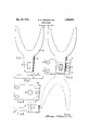
facture. v c In the drawings Figure 1 represents a 7 front view of the movable jaw member; Figure 2 is an upward view of themovable 2G jaw member taken on Figure 1. Figure3 represents a front view ofthe stationary member, or baseplate. Figure 4 is an upward view of the stationary baseplate, taken on Figure 3. V Figure '5 is a front elevation 0t.
the device assembl di The movable jaw member is formedofa suitable material of uniformithickness, its
upper portion,- 12, or jaw, being preferably serrated as indicated by drawing in order to L3 efiectively grip the bone. Its lower portion, or shank, 6, which I shall call the bolt, tapers gradually in width from its upper to lower j extremities, and a slot 7 is formed through its center. The, right band edge otthe bolt is bevelled, asindicated more clearlyinFigure 2. 1 V
V The stationary member,.or base plate, 0011+ sists of a'flat plate, in which'screw holes "9 are provided to permit its being rigidly'fixed 40 to the meat-cutting block; Two lockinglugs. 10 and 11 are integrally formed upon the plate ners.
member, and their left hand edges are undercut at an angle coincidin withthean gle of.
the bevel given tothe e ge otthe tapered 7 bolt 6 of the movable jaw member.
5 V The movable jaw memberiis superimposed tionary member with sufficientplooseness and freedom as to permit the movable member to at its upper and lower left handcon" V As indicated by-Figure 4,'these lugs have a projection from the face of the plate equal to the'thickness of the =movable=jaw upon the stationary baseplate and connected it: i 1 l to it by a headed pivot 8 through the slot 7, so that the movable jaw member has a vertical motion with relation to the stationary I 7 member in addition to its pivoting motionga about the pivot 8.
' When the movable jaw member'israisedto I '7 c its operative position,fitszweight willpause it to dropupon itsflpivot so thatthelower end of the bolt 6 falls slightly below'the upper edge of the lug 11,-? whereby the movable member becomes looked through the wedging action of, the lugs 10 and 11 upon thetapered 1 bolt 6, forcing it against the pivot8; In this V p 7 1 position, absoluteyrigidityr-is securedby-the-fi, 3 combined separate wedging effects of the taper and ofthe bevelled edge of the bolt 6, the taper-taking up the side play between the pivot 8 and the lugslQ and-1 1, by wedging the bolt Gagainst the pivot, while the bevelled edge prevents any twistingot the bolt 6 arising from the play betweenthe pivot '8 j v v andthe slot 7. By this means, it is possible to connect the mov'able;'member tothe sta1..
be thrownintO and outjof, an operjative position very easily and quiokly, at thefsame' time t securing absolute immobility-when the mem bersare engaged-in operative'position. To V 8!! disengage the movable member, itis raised. I p 1 slightly so thatthe lower endof bolt 6,,clea'r-, I V ingthe upper edgebf filleflug 11, describes,
an are between the lugs 10 and Has the'jaw is swung to'lone side and fallsto its inoperatime position, below thesurfac'e'of the, meatcutting block, as indicated by the dottedlines i 'in Figure.5.' Q M 1.-"Afolding benohvise, comprisinga tionary baseplate anda iboltbperativel mounted thereon, said plate'havingsajpivqt pin and two lugs proj ecting" from one face fthereof, the lugs beingvertic'ally spacedlfrom each other and having theirendsllongia tudinally spaced from the pivot pin, said;
nbol -tihaving alongitudinal slot therein '-adj'a-' jcent oneend thereofthro ugh; which the pivot pin projects, saidsl'ot termin'atingi at a dis- "1 1 tance from the en'd'jof the bolt' equaltoless j than the distance :ffomi the pivot pin to the adjacentends of the lugs, the slotted end of the bolt being wedge-shapedrand cooperating I g p with the pivot pin andlugs when in operative position to form a wedging action.
2. A folding bench vise as in claim 1, the ends of the lugs adjacent the pivot ;.pin loeing nndercut=to coincide: with a; ibevel formed upon the edge of the bolt. 7
- GEORGE CHRISTIAN BRAUMULLER.
Priority Applications (1)
| Application Number | Priority Date | Filing Date | Title |
|---|---|---|---|
| US334537A US1859954A (en) | 1929-01-23 | 1929-01-23 | Bone-holder |
Applications Claiming Priority (1)
| Application Number | Priority Date | Filing Date | Title |
|---|---|---|---|
| US334537A US1859954A (en) | 1929-01-23 | 1929-01-23 | Bone-holder |
Publications (1)
| Publication Number | Publication Date |
|---|---|
| US1859954A true US1859954A (en) | 1932-05-24 |
Family
ID=23307683
Family Applications (1)
| Application Number | Title | Priority Date | Filing Date |
|---|---|---|---|
| US334537A Expired - Lifetime US1859954A (en) | 1929-01-23 | 1929-01-23 | Bone-holder |
Country Status (1)
| Country | Link |
|---|---|
| US (1) | US1859954A (en) |
Cited By (2)
| Publication number | Priority date | Publication date | Assignee | Title |
|---|---|---|---|---|
| US5673898A (en) * | 1996-03-27 | 1997-10-07 | American Rescue Technology Incorporated | Hydraulic ram attachment for a rescue tool |
| WO2008008241A3 (en) * | 2006-07-14 | 2008-11-13 | Roy J Couvillion | Method and apparatus for preparing bone grafts |
-
1929
- 1929-01-23 US US334537A patent/US1859954A/en not_active Expired - Lifetime
Cited By (3)
| Publication number | Priority date | Publication date | Assignee | Title |
|---|---|---|---|---|
| US5673898A (en) * | 1996-03-27 | 1997-10-07 | American Rescue Technology Incorporated | Hydraulic ram attachment for a rescue tool |
| US5732932A (en) * | 1996-03-27 | 1998-03-31 | American Rescue Technology Incorporated | Hydraulic ram attachment for a rescue tool |
| WO2008008241A3 (en) * | 2006-07-14 | 2008-11-13 | Roy J Couvillion | Method and apparatus for preparing bone grafts |
Similar Documents
| Publication | Publication Date | Title |
|---|---|---|
| US2299178A (en) | Adjustable boat seat | |
| US1550751A (en) | Portable vise | |
| US1859954A (en) | Bone-holder | |
| DE518237C (en) | Adjustable umbrella holder | |
| US342187A (en) | Clamp | |
| US1629246A (en) | Clamp | |
| US1539857A (en) | Device for cleaning walls and ceilings | |
| US1395308A (en) | Staging-support | |
| US1792024A (en) | Hack saw | |
| US2231646A (en) | Vise | |
| US1912313A (en) | Vise | |
| US1165245A (en) | Knife-sharpener. | |
| US1150962A (en) | Hand-clamp. | |
| US1500795A (en) | Clamp | |
| US2465168A (en) | Hand miter | |
| US1143749A (en) | Saw-holding device. | |
| US1168049A (en) | Post pipe-vise. | |
| DE835242C (en) | Hand saw with adjustable handle | |
| US1220108A (en) | Saw-clamp. | |
| US1482780A (en) | Saw set | |
| US1069448A (en) | Work-bench. | |
| US1871176A (en) | Combination bevel, squaring, and leveling device | |
| US1402001A (en) | Tool holder | |
| US2448200A (en) | Planer | |
| US2288998A (en) | Vise cutter |