US1859912A - Bed wardrobe - Google Patents
Bed wardrobe Download PDFInfo
- Publication number
- US1859912A US1859912A US331408A US33140829A US1859912A US 1859912 A US1859912 A US 1859912A US 331408 A US331408 A US 331408A US 33140829 A US33140829 A US 33140829A US 1859912 A US1859912 A US 1859912A
- Authority
- US
- United States
- Prior art keywords
- bed
- box
- cover
- beneath
- holder
- Prior art date
- Legal status (The legal status is an assumption and is not a legal conclusion. Google has not performed a legal analysis and makes no representation as to the accuracy of the status listed.)
- Expired - Lifetime
Links
- 208000027418 Wounds and injury Diseases 0.000 description 1
- 230000001154 acute effect Effects 0.000 description 1
- 230000006378 damage Effects 0.000 description 1
- 208000014674 injury Diseases 0.000 description 1
- 239000010985 leather Substances 0.000 description 1
- 239000002184 metal Substances 0.000 description 1
- 238000005192 partition Methods 0.000 description 1
Images
Classifications
-
- A—HUMAN NECESSITIES
- A47—FURNITURE; DOMESTIC ARTICLES OR APPLIANCES; COFFEE MILLS; SPICE MILLS; SUCTION CLEANERS IN GENERAL
- A47C—CHAIRS; SOFAS; BEDS
- A47C17/00—Sofas; Couches; Beds
- A47C17/86—Parts or details specially adapted for beds, sofas or couches not fully covered by any single one of groups A47C17/02 - A47C17/84
Definitions
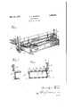
- Fig. l is a perspective view illustrating an embodiment of my invention, the holder or receptacle being shown in full lines partiall ly withdrawn from under the bed to give access to its interior;
- Fig. 2 is a vertical section showing the holder or receptacle in a closed position
- Fig. 8 is a detail view in section of a different embodiment of my invention.
- my invention compreheiids the combination or association with a bed supported on legs so as to provide a space ot' substantial depth from the mattress or springs to the floor, of a movable box or container
- Whose dimensions utilize to thevbest possible advantage the space beneath the bed, and having such form and appearance as to be harmonious with the bed structure and which is capable of movement between a position under the bed to one sutticiently from beneath the bed to give access to its interior for placing therein or removal therefrom of articles of clothing or wearing apparel, or any other objects requiring to be thus temporarily stored away.
- the size and proportions ot' the box or holder may be such as to permit its placing under the bed from the side thereof, and there may be one for each I side of the bed or at the foot; or there could be boxes or receptacles at both sides and the foot Y tical side walls, and atop or (joven-12, the interior of the body being divided by partitions into as many separate compartments as may be desired, and of different dimensions to readilyV hold various articles of apparel.
- the dimensions vertically and longitudinally are such as to be slightly less than the vertical and longitudinal Vdimensions of the-space beneath the bedl and the dimensions'transverselyl are such that fromiffront to back they will not be greater than will allow the complete placing of the box or holder within a vertical plane passing through the outer side of the side rail or the end rail of the bedstead, according to the position of the receptacle or holder with reference to the bed.
- Wheels or casters or domes of silence are applied to the bottom of the body to enable the movement of the receptacle or holder under and from beneath the bed easily edected and without injury to iioor or floor covering.
- the cover, l2 may be hinged or pivoted, but ispreferably horizontally slidable so that it will be unnecessary wholly to withdraw the holder or receptacle for beneath the bed to give access to its interior, which would be necessary if the cover is hinged. And of course, a hinged cover would require ⁇ the proy vision of lsome means to yhold it in lan open wardrobe may match'or harmonize with that of the bed.
- the sliding top or cover has at each end a downwardly extending flange, 13, that overlaps and lies against the upper edge of the box end both for the purpose of keeping the cover'in position against endwise movement and to make a clust-tight joint'and atthe rear it has a similar flange, 14, for the two purposes of making a dust-tight joint and to constitute a stop to torwardmovementv ot the cover whenA it is drawn forward to its closed position.
- On the underside of the while allowing continued movement of the cover is a downwardly extending lug o1 probox. jection, 15, which, when the cover is moved In testimony whereof I hereunto aiix my backward strikes the back wall of the box and signature.
- Automatic closing and unclosing the box by providing devices that cooperate with the bedstead may be and preferably is dsone.
- I attach to the cover at each end a finger, 16, adapted 80 to project upward in position to bear against the inner side of the side rail of the bed, so that when the box is drawn outward from beneath the bed, it will slide outward leaving 90 the cover behind and said iinger, 16, is pivot- B5 ed so thatl it may be swung from a vertical position to a horizontal position where it affords no obstruction to the outward movement of the cover with the box should it not be desired to have the automatic action in 90 which case the cover is moved to open the box by hand.
- the automatic closing of the box is effected 95 by a suitable connection with the bedstead which as shown in Figs. 1 and 2 is a strap or straps, 17, of leather or webbing having a rigid hook, 18, to catch over the edge of the side rail of the bed, and the strap attached 100 at its other end to the cover at or near the rear edge.
- a suitable connection with the bedstead which as shown in Figs. 1 and 2 is a strap or straps, 17, of leather or webbing having a rigid hook, 18, to catch over the edge of the side rail of the bed, and the strap attached 100 at its other end to the cover at or near the rear edge.
- the cover may have at its rear end sheet metal straps, 19, to catch 110 over the side rail of the bed, and thereby the automatic opening and closing of the box be effected because the cover will be restrained from movement both when the box is drawn Y Y outward from beneath the bed and when it is 115 pushed inward. Said straps also prevent the box being moved too ar beneath the bed.
- What I claim is In combination with a bed, a box or holder v5 normally under the bed and movable trom 120 beneath the bed having dimensions vertically and longitudinally that substantially utilize the space beneath the bed, a cover for the box that is movable bodily with the box, means to connect cover and bed that limit move- Y 125 ment of the box when box and cover are moved beneath the bed and coacting disconnected means on cover and bed that stop movement of the cover when cover and box are drawn together from beneath the bed 130
Landscapes
- Health & Medical Sciences (AREA)
- General Health & Medical Sciences (AREA)
- Nursing (AREA)
- Combinations Of Kitchen Furniture (AREA)
- Special Chairs (AREA)
Description
May Z4, 1932. Agi.4 BROKER BED wARDRoE Filed Jan. 1o, 1929 Patented May 24, 1932 Uni-TED STATES PATENT orifice I ANNIE LAURIE BROOKER, 0F RICHMOND, VIRGINIA, ASSIGNOR T0 BOYCE D..BR0OKR,`
0F RICHMOND, VIRGINIA BED WARDROBE Application led January 10, 1929.v Serial No. 331,408.
In these days of small rooms, especially in apartment houses, it is a serious problem to iind storage or holding room or space and the problem is especially acute as to articles such as parts of wearing apparel that require repeated temporary storage. The object of my invention is to meet this situation by utilizing space that otherwise is not utilized or is wasted. Beneath the ordinary bed, as is well known, is a large amount of space and in producing my invention, I make use of that space.
My invention consists in whatever is described by or is included within the terms or scope of the appended claim.
In the drawings: Fig. l is a perspective view illustrating an embodiment of my invention, the holder or receptacle being shown in full lines partiall ly withdrawn from under the bed to give access to its interior;
Fig. 2 is a vertical section showing the holder or receptacle in a closed position;
Fig. 8 is a detail view in section of a different embodiment of my invention.
Generally described, my invention compreheiids the combination or association with a bed supported on legs so as to provide a space ot' substantial depth from the mattress or springs to the floor, of a movable box or container Whose dimensions utilize to thevbest possible advantage the space beneath the bed, and having such form and appearance as to be harmonious with the bed structure and which is capable of movement between a position under the bed to one sutticiently from beneath the bed to give access to its interior for placing therein or removal therefrom of articles of clothing or wearing apparel, or any other objects requiring to be thus temporarily stored away. The size and proportions ot' the box or holder may be such as to permit its placing under the bed from the side thereof, and there may be one for each I side of the bed or at the foot; or there could be boxes or receptacles at both sides and the foot Y tical side walls, and atop or (joven-12, the interior of the body being divided by partitions into as many separate compartments as may be desired, and of different dimensions to readilyV hold various articles of apparel. The dimensions vertically and longitudinally are such as to be slightly less than the vertical and longitudinal Vdimensions of the-space beneath the bedl and the dimensions'transverselyl are such that fromiffront to back they will not be greater than will allow the complete placing of the box or holder within a vertical plane passing through the outer side of the side rail or the end rail of the bedstead, according to the position of the receptacle or holder with reference to the bed.
Wheels or casters or domes of silence are applied to the bottom of the body to enable the movement of the receptacle or holder under and from beneath the bed easily edected and without injury to iioor or floor covering.
The cover, l2, may be hinged or pivoted, but ispreferably horizontally slidable so that it will be unnecessary wholly to withdraw the holder or receptacle for beneath the bed to give access to its interior, which would be necessary if the cover is hinged. And of course, a hinged cover would require` the proy vision of lsome means to yhold it in lan open wardrobe may match'or harmonize with that of the bed.
The sliding top or cover has at each end a downwardly extending flange, 13, that overlaps and lies against the upper edge of the box end both for the purpose of keeping the cover'in position against endwise movement and to make a clust-tight joint'and atthe rear it has a similar flange, 14, for the two purposes of making a dust-tight joint and to constitute a stop to torwardmovementv ot the cover whenA it is drawn forward to its closed position. On the underside of the while allowing continued movement of the cover is a downwardly extending lug o1 probox. jection, 15, which, when the cover is moved In testimony whereof I hereunto aiix my backward strikes the back wall of the box and signature. thus prevents the cover being pushed wholly ANNIE LAURIE BROOKER. 70 off the top of the box, and this stop, 15, may be so located as to leave a substantial portion of the cover at the front still lying over the top of the box and yet not interfere with access to the interior of the box. 7 5
Automatic closing and unclosing the box by providing devices that cooperate with the bedstead may be and preferably is dsone. Thus, as shown in Figs. 1 and 2, I attach to the cover at each end a finger, 16, adapted 80 to project upward in position to bear against the inner side of the side rail of the bed, so that when the box is drawn outward from beneath the bed, it will slide outward leaving 90 the cover behind and said iinger, 16, is pivot- B5 ed so thatl it may be swung from a vertical position to a horizontal position where it affords no obstruction to the outward movement of the cover with the box should it not be desired to have the automatic action in 90 which case the cover is moved to open the box by hand. When the finger, 16, is in position to engage the side rail of the bedstead to hold the cover for moving out-ward with the box, the automatic closing of the box is effected 95 by a suitable connection with the bedstead which as shown in Figs. 1 and 2 is a strap or straps, 17, of leather or webbing having a rigid hook, 18, to catch over the edge of the side rail of the bed, and the strap attached 100 at its other end to the cover at or near the rear edge. When the stop iinger, 16, is not used and the cover moves outward with the box when withdrawn from beneath the bed, 40 the flexible strap will permit that action and y '105 the strap, of course, will serve as a stop to prevent the box being moved too far underv the bed.
As shown in Fig. 3 the cover may have at its rear end sheet metal straps, 19, to catch 110 over the side rail of the bed, and thereby the automatic opening and closing of the box be effected because the cover will be restrained from movement both when the box is drawn Y Y outward from beneath the bed and when it is 115 pushed inward. Said straps also prevent the box being moved too ar beneath the bed.
What I claim is In combination with a bed, a box or holder v5 normally under the bed and movable trom 120 beneath the bed having dimensions vertically and longitudinally that substantially utilize the space beneath the bed, a cover for the box that is movable bodily with the box, means to connect cover and bed that limit move- Y 125 ment of the box when box and cover are moved beneath the bed and coacting disconnected means on cover and bed that stop movement of the cover when cover and box are drawn together from beneath the bed 130
Priority Applications (1)
| Application Number | Priority Date | Filing Date | Title |
|---|---|---|---|
| US331408A US1859912A (en) | 1929-01-10 | 1929-01-10 | Bed wardrobe |
Applications Claiming Priority (1)
| Application Number | Priority Date | Filing Date | Title |
|---|---|---|---|
| US331408A US1859912A (en) | 1929-01-10 | 1929-01-10 | Bed wardrobe |
Publications (1)
| Publication Number | Publication Date |
|---|---|
| US1859912A true US1859912A (en) | 1932-05-24 |
Family
ID=23293828
Family Applications (1)
| Application Number | Title | Priority Date | Filing Date |
|---|---|---|---|
| US331408A Expired - Lifetime US1859912A (en) | 1929-01-10 | 1929-01-10 | Bed wardrobe |
Country Status (1)
| Country | Link |
|---|---|
| US (1) | US1859912A (en) |
Cited By (6)
| Publication number | Priority date | Publication date | Assignee | Title |
|---|---|---|---|---|
| US4490864A (en) * | 1983-02-14 | 1985-01-01 | Wicker Jr Roy W | Shelter bed |
| US4937902A (en) * | 1988-06-15 | 1990-07-03 | Kathy Ceike Shapiro | Crib structure with slidable steps providing storage compartments |
| US6293055B1 (en) * | 1999-07-19 | 2001-09-25 | Dale D. Watson | Combined bed and shelter device |
| US7917977B1 (en) * | 2008-02-05 | 2011-04-05 | Steven Remis | Box spring safe |
| ITPN20110018A1 (en) * | 2011-03-21 | 2012-09-22 | Dielle S P A | REMOVABLE DRAWER FOR FURNITURE |
| US20180220803A1 (en) * | 2017-01-06 | 2018-08-09 | Kenneth Blueford | Multi-function shelter system |
-
1929
- 1929-01-10 US US331408A patent/US1859912A/en not_active Expired - Lifetime
Cited By (6)
| Publication number | Priority date | Publication date | Assignee | Title |
|---|---|---|---|---|
| US4490864A (en) * | 1983-02-14 | 1985-01-01 | Wicker Jr Roy W | Shelter bed |
| US4937902A (en) * | 1988-06-15 | 1990-07-03 | Kathy Ceike Shapiro | Crib structure with slidable steps providing storage compartments |
| US6293055B1 (en) * | 1999-07-19 | 2001-09-25 | Dale D. Watson | Combined bed and shelter device |
| US7917977B1 (en) * | 2008-02-05 | 2011-04-05 | Steven Remis | Box spring safe |
| ITPN20110018A1 (en) * | 2011-03-21 | 2012-09-22 | Dielle S P A | REMOVABLE DRAWER FOR FURNITURE |
| US20180220803A1 (en) * | 2017-01-06 | 2018-08-09 | Kenneth Blueford | Multi-function shelter system |
Similar Documents
| Publication | Publication Date | Title |
|---|---|---|
| US2357555A (en) | First-aid kit | |
| US1859912A (en) | Bed wardrobe | |
| US1861802A (en) | Combination toilet tank cover and cabinet | |
| US2265671A (en) | Cabinet | |
| US1994857A (en) | Portable bar | |
| US1456247A (en) | Seat box for ford sedans | |
| US2301856A (en) | Cabinet | |
| US2222318A (en) | Combination packing case and desk | |
| US313768A (en) | pringle | |
| US1694470A (en) | Combination trunk | |
| US2201354A (en) | Attachment for arm rest for furniture | |
| US1631780A (en) | Display chest for silverware | |
| US1458024A (en) | Coal box | |
| US1593176A (en) | Convertible furniture | |
| US1452117A (en) | Convertible furniture | |
| US1980210A (en) | Baby carriage | |
| US1714115A (en) | Article of furniture | |
| US1381874A (en) | Traveling-suitette | |
| JPS5921866A (en) | underground storage equipment | |
| US1689737A (en) | Convertible bed | |
| US509197A (en) | Will c | |
| US1166988A (en) | Combination trunk and dressing-table. | |
| US898549A (en) | Trunk. | |
| US1344257A (en) | Folding bed, dresser, and washstand | |
| US898598A (en) | Folding cot and bath-tub cabinet. |