US1859903A - Folded box - Google Patents
Folded box Download PDFInfo
- Publication number
- US1859903A US1859903A US369536A US36953629A US1859903A US 1859903 A US1859903 A US 1859903A US 369536 A US369536 A US 369536A US 36953629 A US36953629 A US 36953629A US 1859903 A US1859903 A US 1859903A
- Authority
- US
- United States
- Prior art keywords
- box
- tabs
- cuts
- folded
- panel
- Prior art date
- Legal status (The legal status is an assumption and is not a legal conclusion. Google has not performed a legal analysis and makes no representation as to the accuracy of the status listed.)
- Expired - Lifetime
Links
- 238000009740 moulding (composite fabrication) Methods 0.000 description 9
- 238000003490 calendering Methods 0.000 description 4
- 239000000463 material Substances 0.000 description 2
- 241000726103 Atta Species 0.000 description 1
- 230000015572 biosynthetic process Effects 0.000 description 1
- 238000010276 construction Methods 0.000 description 1
- 230000007423 decrease Effects 0.000 description 1
- 239000003292 glue Substances 0.000 description 1
- VKYKSIONXSXAKP-UHFFFAOYSA-N hexamethylenetetramine Chemical compound C1N(C2)CN3CN1CN2C3 VKYKSIONXSXAKP-UHFFFAOYSA-N 0.000 description 1
- 230000008520 organization Effects 0.000 description 1
- 238000006467 substitution reaction Methods 0.000 description 1
- 239000002699 waste material Substances 0.000 description 1
Images
Classifications
-
- B—PERFORMING OPERATIONS; TRANSPORTING
- B65—CONVEYING; PACKING; STORING; HANDLING THIN OR FILAMENTARY MATERIAL
- B65D—CONTAINERS FOR STORAGE OR TRANSPORT OF ARTICLES OR MATERIALS, e.g. BAGS, BARRELS, BOTTLES, BOXES, CANS, CARTONS, CRATES, DRUMS, JARS, TANKS, HOPPERS, FORWARDING CONTAINERS; ACCESSORIES, CLOSURES, OR FITTINGS THEREFOR; PACKAGING ELEMENTS; PACKAGES
- B65D5/00—Rigid or semi-rigid containers of polygonal cross-section, e.g. boxes, cartons or trays, formed by folding or erecting one or more blanks made of paper
- B65D5/42—Details of containers or of foldable or erectable container blanks
- B65D5/44—Integral, inserted or attached portions forming internal or external fittings
- B65D5/52—External stands or display elements for contents
- B65D5/522—Containers provided with decoration or information elements which are displaced to display the contents
- B65D5/5246—Containers provided with decoration or information elements which are displaced to display the contents formed separately from the container or lid
Definitions
- This invention relates to folded boxes, and more particularly to'a' new and improved fastening device for' attaching thevarious' ,ing this element parts of a boxformedf-rom a folded blank.
- the invention relates. specifically to a folded box havinga detachable cover or ad:- vertising display card, and means for attachto the box and locking the parts in position. This is accomplished by' providing a tongue having infolded tabs associated therewith which are adapted tolock the parts when in extended position.
- the invention provides means: for saving 2 material in the formation of the box, particularly when the sides" of the cover are ofless depth than the box itself; and eliminates the waste of material which would be present if the entire assembly were formed of a one piece blank.
- a display card to a box and for forming the display card togetherwith the box blank in a a single operation and claimed.
- the invention also provides for attaching
- Back -12 isprovided with a'pair of parallel-slits 18 formin therebetween 'a strap 14 fforxa purpose tovb e described;
- the cover member be formed from a blank suitably cut and scored to' provide top 15, side flap 16;" end attaching panel 18. Flaps I6 and 17Jmay be bent; downwardly 'at right anglesto 't-op'15 as shown in Fig. 1 and se cured in any convenientmanner.
- Panel-18is providedwith cutsl20 and/21 as shown in Fig. 2 may I and creases 22 which are.preferablyinclined I I to theibottom triangular tabs 23 of saidpa nel whereby the between creases 22 and cuts 21 are substantially equilateral.
- Cuts 20 form extensions of creasesr22- and lie -outside of a a a w In attachingthe'cover ihembertothefoldabout creases. 22-as shown in Fig? 4a to form Thisflmember is insertedaadownwardly until strap 14: enterscuts 20 asf shown in Fig. 5. .Tabs 23 are then bentou twardly 190' edbox triangular tabs' 23 arebent inwardly a. a pointedmemberL-which "is inserted under v strap. 14.
- an advertising or display card can be formed in amanner similar to the cover member and secured to the box as desired.
- the advertising card is formed with a display surface 30 and an attaching. panel 31.
- the attacha ingpanel is provided with slots20 and 21 against being raised by strap 14 contacting and creases 22 in the-manner pointed out in connection with-the cover member.
- a plurality of flaps 32:1nay be formed by making arcuate cuts, 33 in. the back of said 1 box.
- the lower portion thereof may be inserted under flaps 32 and securely locked thereby.- In this position the panel is locked with'cuts 21 and isprevented from being low- .ered by tabs 32. It is-therefore positively attached to the box and danger ofaccidental removal is eliminated.
- the panel is formed asa separate piece and may be turned with the calendered surface to the front before it is attached tothe box in the manner above pointed out.
- a back member having a pair of parallel cuts therein to form a strap therebetween, a separable J element having folded-tabs, said tabs being arranged tobe folded into overlapping position to 'permit said element to be insertedunder said strap and to be unfolded into extended position to lock said element against withdrawal.
- a separable 3 member therefor having anattaching panel, a pair of diagonally extending creases form ing a V at the bottom of said panel, a pair of cuts formed on an extension of said creases,
- a second pair oficuts extending from said said panel to be se- 7 parallel cuts forming a strap theretendingcreases forming a V at the bottom of Y said panel, a pair of cuts formed on an ex- I tension of said creases, a second pair of cuts extending from said first cuts at microwavele triangular tabs, said tabs being adapted to'be'folded'about said relationship to perfor attaching purposes.
- a back member having a pair of parallel cuts" forming a strap therebetween, a separable member therefor having an attaching panel, a pair of diagonally extending creases. forming a -V atthe bottom of said panel, a pair of cuts formed on an extension of said creases, a second pair of cuts extending from. said first mentioned cuts at an angle with saidcreases to form triangular'tabs, said tabs being adapted to be folded about said creases into overlapping relationsh p whereby they may be inserted. under said strap for attaching purposes, said strap engaging with said first mentioned cuts to permit sald tabs to be unfolded into extended position and engaging with said second mentioned cuts'to rable member.
- a back member having a pair of parallel cuts forminga strap therepre'vent removal of said sepabetween, a separable member therefor hava ing an attaching panel, a pair of diagonally extending creases forming a V at the bottom f of said panel, a pair of cuts formed on an extension of said creases, a second pair of cuts extending from said first cuts at an angle with said creases to form triangular I tabs, said tabs being adapted to be folded about said creases into overlapping relationship to permit said tabs to be inserted under said strap for attaching purposes, said back a I member having an upwardly extending .flap adapted to engage said panel to prevent withdrawal thereof.
- a back member having a pair of parallel cuts therein to form a strap therebetween, a separable element having folded tabs, said tabs being arranged to be folded into overlapping position to permit said element to be inserted under said strap and to be unfolded into extended position to lock said element against withdrawal, said back member having an upwardly extending a flap for engaging said element and limiting the movement thereof.
Landscapes
- Engineering & Computer Science (AREA)
- Mechanical Engineering (AREA)
- Cartons (AREA)
Description
P. WELLMAN' 1,859,903
FOLDED BOX Filed June 10, 1929 2 Sheets-Sheet 2 20 @IIAZfNTOR. W Q21 g m )n.
ATTO VEY CHARLES P. wELILMAiT,
Patented May 24, 1932, v
or wEs'r Melanesia irAssAc HusErrrs, As'sIGivon or m ses 1 ro GHAMPE s. animiaws,oFcH TTANwGA,TEN ESSE Application filed June 10,
This invention relates to folded boxes, and more particularly to'a' new and improved fastening device for' attaching thevarious' ,ing this element parts of a boxformedf-rom a folded blank.
The invention relates. specifically to a folded box havinga detachable cover or ad:- vertising display card, and means for attachto the box and locking the parts in position. This is accomplished by' providing a tongue having infolded tabs associated therewith which are adapted tolock the parts when in extended position.
The invention provides means: for saving 2 material in the formation of the box, particularly when the sides" of the cover are ofless depth than the box itself; and eliminates the waste of material which would be present if the entire assembly were formed of a one piece blank.
a display card to a box and for forming the display card togetherwith the box blank in a a single operation and claimed.
a The invention also provides for attaching;
The invention also consistsin certain new and original features f construction and comblnations of parts hereinafter set forth Although the novel features whichare believed to-be characteristic of this invention will be particularly pointed out-in the claims appended hereto, the invention itself, as to Fig. 4 isan: end e1 the mode of its operation-and the man'nerof its organization may be better understood by referring to the itsobjects and advantages,
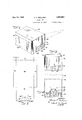
following description taken connection with the accompanyingdrawings forming a part thereof, in which Q a p p Fig. 1- is a perspectiveview showing the box and cover in closed position Fig. 2 is a plan view of the'bla'nk from which the cover is formed; a V V I p f. 4 Fig, 3 is aperspective view of the box with thecoverremoved; 1 y I v 1 V evation of theboxshowing the means for attachingthe cover;'} 7, Fig; 5 is an 'endvelevation of the box and cover showing a furtherstep in thelattache members '10,- front 6 1s an end elevatioriiof the boxand FOLDED BOX 1929. Ser iaFNm 369,536. 1
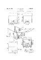
"covershowing the cover-attached and locked n PQSltiOn; "-Fig. 7 isa and isplay card atta h d; v
FigQ'B "s a plan viewof, the blank from brokenperspective of the box Whichthe display cardisforme'dj and- Fig. 9 is'a section takenon'theline 99 Of-FigP'Z. V 7 Likereference in-the several figures of "the drawingsp: 1
characters denote like parts V a In the following description and inthe claims parts will be names'for convenience, but they areintended to" be as generic in their application to; similar parts-asthe artwill'perrnit- Referring identified by specific 05: to the drawings, and more particul'arly' to Fig'snl and the invention'is I shown asapplied to a box comprisingside 11" and back 12 which may be formed together: with a bottom member (not shown) from a blank and'folded into box form in any convenient manner. Back -12 isprovided with a'pair of parallel-slits 18 formin therebetween 'a strap 14 fforxa purpose tovb e described; The cover member be formed from a blank suitably cut and scored to' provide top 15, side flap 16;" end attaching panel 18. Flaps I6 and 17Jmay be bent; downwardly 'at right anglesto 't-op'15 as shown in Fig. 1 and se cured in any convenientmanner. 2 1 Panel-18is providedwith cutsl20 and/21 as shown in Fig. 2 may I and creases 22 which are.preferablyinclined I I to theibottom triangular tabs 23 of saidpa nel whereby the between creases 22 and cuts 21 are substantially equilateral. Cuts 20 form extensions of creasesr22- and lie -outside of a a a w In attachingthe'cover ihembertothefoldabout creases. 22-as shown in Fig? 4a to form Thisflmember is insertedaadownwardly until strap 14: enterscuts 20 asf shown in Fig. 5. .Tabs 23 are then bentou twardly 190' edbox triangular tabs' 23 arebent inwardly a. a pointedmemberL-which "is inserted under v strap. 14.
into their original position and fthe panel 1 raised until strap 14' Tengages' the cuts; 2- 1*as f shown in Fig.
- cover is securelyfattached, cannot be res figWheninthis position the H a 1Q? Y- moved without again folding triangular tabs 23 and reversing the attaching operation. The tabs 23 provide an eflicient lock and areheld in extended position by meansof strap 14. It is to be noted that they cannot again'bebroughtinto folded position until panel 18 is slipped downwardlyjto'the position shown in Fig. 5. This movement is pretently detached.
vented by thecover itself when the box is in closed position. Consequently there is no possibility of the cover becoming 'inadver-' An advertising or display card can be formed in amanner similar to the cover member and secured to the box as desired. As more fully shown inFigs; 7,to 9, the advertising card is formed with a display surface 30 and an attaching. panel 31. The attacha ingpanel is provided with slots20 and 21 against being raised by strap 14 contacting and creases 22 in the-manner pointed out in connection with-the cover member. In case it is-desired to prevent the panel from extending to the bottom of the back 12 of the box, a plurality of flaps 32:1nay be formed by making arcuate cuts, 33 in. the back of said 1 box. After the panel has been attached in the mannerpointed out in connection with Figs. 4 to 6, the lower portion thereof may be inserted under flaps 32 and securely locked thereby.- In this position the panel is locked with'cuts 21 and isprevented from being low- .ered by tabs 32. It is-therefore positively attached to the box and danger ofaccidental removal is eliminated.
In forming a box and advertlsing card 1t is frequently desirable, in the interest of economy,'to provide the same with one calendered and one .uncalendered surface. If'the card were formed integrally' with the box and folded into display position the calendered surface would appear. on the outside of the box and'at the rear of the card. Obviously fordisplaypurposes it is preferable to have the calendered or printed surface of the card appear on the front, facing the contents of the box to be displayed. The presentin vention permits this to be accomplished and the box and panel to be formed and printed of the folded box,
in a single operation, since the panel is formed asa separate piece and may be turned with the calendered surface to the front before it is attached tothe box in the manner above pointed out. I
.The .present invention in addition to'ef- .fectingthe saving in stock and in the printing operations as above pointed. out, eliminates the use of attaching means such as glue, rivets, etcQand thereby, decreases the g cost of assembling. a
r vIt is obvious that the above disclosed'lock can be used forthe securing of various portions and is not limited tothe particular embodiment which has been disclosed for purposes of illustration. It may triangular tabs,
with said creases to form creases into overlapping 'mit said tabs to be'inserted under saidstrap be used in general in any location wherein is desired to secure two elements of a flexible blank.-
While certain novel features of the invention have been shown and described and are pointed out in, the annexed claims, it will be understood that various omissions,.substitutions and changes in theforms and details of the device. illustrated and in its operation may be made by those skilled in the art without departing from the spirit of the invention.
i What is claimed is:
1. In a folded box, a back member having a pair of parallel cuts therein to form a strap therebetween, a separable J element having folded-tabs, said tabs being arranged tobe folded into overlapping position to 'permit said element to be insertedunder said strap and to be unfolded into extended position to lock said element against withdrawal. 7
2. In combination with a box, a separable 3 member therefor having anattaching panel, a pair of diagonally extending creases form ing a V at the bottom of said panel, a pair of cuts formed on an extension of said creases,
a second pair oficuts extending from said said panel to be se- 7 parallel cuts forming a strap theretendingcreases forming a V at the bottom of Y said panel, a pair of cuts formed on an ex- I tension of said creases, a second pair of cuts extending from said first cuts atanfangle triangular tabs, said tabs being adapted to'be'folded'about said relationship to perfor attaching purposes. r
4., Ina folded box, a back member having a pair of parallel cuts" forming a strap therebetween, a separable member therefor having an attaching panel, a pair of diagonally extending creases. forming a -V atthe bottom of said panel, a pair of cuts formed on an extension of said creases, a second pair of cuts extending from. said first mentioned cuts at an angle with saidcreases to form triangular'tabs, said tabs being adapted to be folded about said creases into overlapping relationsh p whereby they may be inserted. under said strap for attaching purposes, said strap engaging with said first mentioned cuts to permit sald tabs to be unfolded into extended position and engaging with said second mentioned cuts'to rable member.
5. In a folded box, a back member having a pair of parallel cuts forminga strap therepre'vent removal of said sepabetween, a separable member therefor hava ing an attaching panel, a pair of diagonally extending creases forming a V at the bottom f of said panel, a pair of cuts formed on an extension of said creases, a second pair of cuts extending from said first cuts at an angle with said creases to form triangular I tabs, said tabs being adapted to be folded about said creases into overlapping relationship to permit said tabs to be inserted under said strap for attaching purposes, said back a I member having an upwardly extending .flap adapted to engage said panel to prevent withdrawal thereof.
6. Ina folded box, a back member having a pair of parallel cuts therein to form a strap therebetween, a separable element having folded tabs, said tabs being arranged to be folded into overlapping position to permit said element to be inserted under said strap and to be unfolded into extended position to lock said element against withdrawal, said back member having an upwardly extending a flap for engaging said element and limiting the movement thereof. a
In testimony whereof I have hereunto set;
CHARLES P. WELLMAN,
my hand.
Priority Applications (1)
| Application Number | Priority Date | Filing Date | Title |
|---|---|---|---|
| US369536A US1859903A (en) | 1929-06-10 | 1929-06-10 | Folded box |
Applications Claiming Priority (1)
| Application Number | Priority Date | Filing Date | Title |
|---|---|---|---|
| US369536A US1859903A (en) | 1929-06-10 | 1929-06-10 | Folded box |
Publications (1)
| Publication Number | Publication Date |
|---|---|
| US1859903A true US1859903A (en) | 1932-05-24 |
Family
ID=23455870
Family Applications (1)
| Application Number | Title | Priority Date | Filing Date |
|---|---|---|---|
| US369536A Expired - Lifetime US1859903A (en) | 1929-06-10 | 1929-06-10 | Folded box |
Country Status (1)
| Country | Link |
|---|---|
| US (1) | US1859903A (en) |
Cited By (8)
| Publication number | Priority date | Publication date | Assignee | Title |
|---|---|---|---|---|
| US2663487A (en) * | 1948-04-17 | 1953-12-22 | Richard E Paige | Expansible carton and detachable cover |
| US3417861A (en) * | 1967-07-06 | 1968-12-24 | Levy Milton | Display container |
| US4477015A (en) * | 1983-05-19 | 1984-10-16 | Container Corporation Of America | Two-piece, self-locking container |
| US5398868A (en) * | 1994-05-31 | 1995-03-21 | Densen; Mark S. | Foldable knock-down storage box with detachable hingeable cover |
| EP0919477A1 (en) * | 1997-11-25 | 1999-06-02 | The Quaker Oats Company | Improved shipping container and display box |
| US20060102707A1 (en) * | 2004-11-12 | 2006-05-18 | Kristin Issler | Shoe box |
| US20090050589A1 (en) * | 2007-08-21 | 2009-02-26 | David James Pedler | Quick Assembly Retail Product Display System and Method for Shipping and Display of Retail Products |
| US8292095B2 (en) | 2009-04-29 | 2012-10-23 | Rock-Tenn Shared Services, Llc | Expandable display system |
-
1929
- 1929-06-10 US US369536A patent/US1859903A/en not_active Expired - Lifetime
Cited By (9)
| Publication number | Priority date | Publication date | Assignee | Title |
|---|---|---|---|---|
| US2663487A (en) * | 1948-04-17 | 1953-12-22 | Richard E Paige | Expansible carton and detachable cover |
| US3417861A (en) * | 1967-07-06 | 1968-12-24 | Levy Milton | Display container |
| US4477015A (en) * | 1983-05-19 | 1984-10-16 | Container Corporation Of America | Two-piece, self-locking container |
| US5398868A (en) * | 1994-05-31 | 1995-03-21 | Densen; Mark S. | Foldable knock-down storage box with detachable hingeable cover |
| EP0919477A1 (en) * | 1997-11-25 | 1999-06-02 | The Quaker Oats Company | Improved shipping container and display box |
| US20060102707A1 (en) * | 2004-11-12 | 2006-05-18 | Kristin Issler | Shoe box |
| US7392931B2 (en) * | 2004-11-12 | 2008-07-01 | Columbia Insurance Company | Shoe box |
| US20090050589A1 (en) * | 2007-08-21 | 2009-02-26 | David James Pedler | Quick Assembly Retail Product Display System and Method for Shipping and Display of Retail Products |
| US8292095B2 (en) | 2009-04-29 | 2012-10-23 | Rock-Tenn Shared Services, Llc | Expandable display system |
Similar Documents
| Publication | Publication Date | Title |
|---|---|---|
| US2973086A (en) | Cartons | |
| US1576672A (en) | Advertising display easel | |
| US2701089A (en) | Carton construction | |
| US3224660A (en) | Stabilized cartons | |
| US1669139A (en) | Collapsible box | |
| US1859903A (en) | Folded box | |
| US1837602A (en) | Securing means for closures | |
| US2503379A (en) | Article holding and display container | |
| US2304362A (en) | Interlocking means for boxes | |
| US439993A (en) | bailey | |
| US2730232A (en) | Display carton | |
| US1821960A (en) | Display box | |
| US1776134A (en) | Folding box | |
| US2079370A (en) | Display | |
| US1909473A (en) | Display box | |
| GB291329A (en) | Improvements in cardboard and the like boxes | |
| US2314304A (en) | Display box | |
| US2346596A (en) | Fan mailing card folder | |
| US1310765A (en) | Paper box | |
| US2149959A (en) | Knock-down display device | |
| US1767734A (en) | Foldable box | |
| US276962A (en) | Feldt | |
| US3380181A (en) | Advertisement attachment for gable-top containers | |
| US2141011A (en) | Carton retaining band | |
| US1515338A (en) | Collapsible display device |