US1857710A - Rotating steam generator - Google Patents
Rotating steam generator Download PDFInfo
- Publication number
- US1857710A US1857710A US490076A US49007630A US1857710A US 1857710 A US1857710 A US 1857710A US 490076 A US490076 A US 490076A US 49007630 A US49007630 A US 49007630A US 1857710 A US1857710 A US 1857710A
- Authority
- US
- United States
- Prior art keywords
- rotor
- water
- steam
- steam generator
- rotating steam
- Prior art date
- Legal status (The legal status is an assumption and is not a legal conclusion. Google has not performed a legal analysis and makes no representation as to the accuracy of the status listed.)
- Expired - Lifetime
Links
- XLYOFNOQVPJJNP-UHFFFAOYSA-N water Substances O XLYOFNOQVPJJNP-UHFFFAOYSA-N 0.000 description 17
- 238000005192 partition Methods 0.000 description 9
- 238000010276 construction Methods 0.000 description 2
- 230000001419 dependent effect Effects 0.000 description 2
- 238000004326 stimulated echo acquisition mode for imaging Methods 0.000 description 2
- 230000001066 destructive effect Effects 0.000 description 1
- 238000001704 evaporation Methods 0.000 description 1
- 230000008020 evaporation Effects 0.000 description 1
- 238000010438 heat treatment Methods 0.000 description 1
- 230000003137 locomotive effect Effects 0.000 description 1
- 230000000979 retarding effect Effects 0.000 description 1
Images
Classifications
-
- F—MECHANICAL ENGINEERING; LIGHTING; HEATING; WEAPONS; BLASTING
- F22—STEAM GENERATION
- F22B—METHODS OF STEAM GENERATION; STEAM BOILERS
- F22B5/00—Steam boilers of drum type, i.e. without internal furnace or fire tubes, the boiler body being contacted externally by flue gas
- F22B5/005—Steam boilers of drum type, i.e. without internal furnace or fire tubes, the boiler body being contacted externally by flue gas with rotating drums
Definitions
- the invention has for its object to make it possible to use the generator as a locomotive boiler, in which case it will 1 be subjected to strong accelerative or retardative actions tending to cause the water level to deviate from the horizontal plane and forcing the main bulk of water towards one end or the other of the boiler,the correct circulation of the water through the rotor bevery much disturbed thereby, and the 1n ro t or will tend to be damaged by burning.
- the rotor is provided interiorly with transverse partition walls suitably intere spaced and provided with a central aperture for the passage of the steam.
- the water level within the rotor is substantially horizontal and extends a little above the lower edges of the apertures in the partition chambers thus formed .withinthe rotor are Now, if for instance a retardation of the train occurs, the water in the chambers is thrown forwardly in the direction of running, and a part of the water is forced into the foremost chambers T which are filled more or less according to their position in axial direction, the water level within the rear chambers taking a position inclining to the horizontal, such inclination being dependent on the amount of retardation. If no partition walls were at walls, so that all compartments or vex-yrs rong; ie-
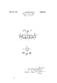
- Fig. 1 shows a longitudinal section
- Fig. 2 a cross section of the rotor according to the invention.
- the feed water is introduced through the pipe 1, and by the hollow pivot 2 it is admitted to the rotor 3.
- the generated steam, and eventually also a certain amount of the water fed in, are delivered through the opposite hollow pivot 4, so as therefrom by means of the pipe 5 to be passed either directly to the place of consumption or at first to a super-heater in'the conventional manner.
- the water inlet and the steam outlet may also be provided in the same pivot and other deviations from the construction described may be used without influence on the invention itself.
- the rotor 3 is subdivided into a convenient number of compartments by means of transverse partition walls 6 positioned at suitable distance'from each other, each of such walls beingprovided with a central aperture ,7, the lower edge of which is positioned a little below the lowest normal water level in the rotor.
- a tubular steam generating element rotatably mounted in asition, means for feeding water into the generating element and means for delivery of steam therefrom, a plurality of transverse partition Walls positioned at suitable interdistances along the Whole length of the tubular steam generating element and extend-- ing to the shell plate around'the whole circumference thereof, and permanentlyopen' central apertures positioned in the partition Walls so that their lower edges area little below the lowest normal water level in the steam generating element only, in order that said apertures shall in part form permanently open communication means between the difierent partitions of the boiler!
Landscapes
- Engineering & Computer Science (AREA)
- Physics & Mathematics (AREA)
- Thermal Sciences (AREA)
- Mechanical Engineering (AREA)
- General Engineering & Computer Science (AREA)
- Muffle Furnaces And Rotary Kilns (AREA)
Description
y 1932 J. v. BLOMQUIST ET AL 7,710
ROTATING STEAM GENERATOR Filed Opt. 20, 1930 of the very partially filled with water.
Patented May 10, 1932 UNITED STATES JOHAN VIKTOR BLOMQUIST AND TORSTEN ASSIGNOR-S TO AKTIEBOLAGET ATMOS, 0
OF SWEDEN ROTATING STEAM Application filed October 20, 1930, Serial Ila/490 Our present invention refers to improvements in steam generators provided with one or more rotating steam generating elements mounted in a fire-place and charged with a quantity of water which does not take part in the rotation so that the water level in each steam generating element or rotor takes a substantially horizontal position. In, view great specific evaporation obtained in steam generators of this kind, it is of the greatest importance that the inner face of the rotor shell is alwayswetted with a sufficient quantity of water throughout, as otherwise the heating will result in stresses which are destructive to the rotor construction.
In spite hereof, the invention has for its object to make it possible to use the generator as a locomotive boiler, in which case it will 1 be subjected to strong accelerative or retardative actions tending to cause the water level to deviate from the horizontal plane and forcing the main bulk of water towards one end or the other of the boiler,the correct circulation of the water through the rotor bevery much disturbed thereby, and the 1n ro t or will tend to be damaged by burning.
In order to do away with these inconveniences and risks the rotor, according to the invention, is provided interiorly with transverse partition walls suitably intere spaced and provided with a central aperture for the passage of the steam. When running at a substantially constant speed on a horizontal track, the water level within the rotor is substantially horizontal and extends a little above the lower edges of the apertures in the partition chambers thus formed .withinthe rotor are Now, if for instance a retardation of the train occurs, the water in the chambers is thrown forwardly in the direction of running, and a part of the water is forced into the foremost chambers T which are filled more or less according to their position in axial direction, the water level within the rear chambers taking a position inclining to the horizontal, such inclination being dependent on the amount of retardation. If no partition walls were at walls, so that all compartments or vex-yrs rong; ie-
handirthieiavateiq 1n: cas
' "I-ntoiand filln.
themes ndtfo lie'imtonTheE rear en f U enterta erleftzemptyea etd m due to dryness. By using the said partition walls it is possible to obtain that the whole interior face of the rotor shellis sufficiently wetted throughout.
The invention is illustrated in the accompanying diagrammatical drawings, wherein Fig. 1 shows a longitudinal section and Fig. 2 a cross section of the rotor according to the invention.
It is to be understood that the invention is independent of the number of rotors comprisingthe whole boiler set in each case, as
all of them are constructed in a similar manner, and the number of partition walls is also variable and mainly dependent on the length of each rotor. 1
Referring to Fig. 1, the feed water is introduced through the pipe 1, and by the hollow pivot 2 it is admitted to the rotor 3. The generated steam, and eventually also a certain amount of the water fed in, are delivered through the opposite hollow pivot 4, so as therefrom by means of the pipe 5 to be passed either directly to the place of consumption or at first to a super-heater in'the conventional manner.
The water inlet and the steam outlet may also be provided in the same pivot and other deviations from the construction described may be used without influence on the invention itself. p
According to the invention, the rotor 3 is subdivided into a convenient number of compartments by means of transverse partition walls 6 positioned at suitable distance'from each other, each of such walls beingprovided with a central aperture ,7, the lower edge of which is positioned a little below the lowest normal water level in the rotor.
What we claim and desire to secure by Letters Patent is In a rotating steam boiler, a tubular steam generating element rotatably mounted in asition, means for feeding water into the generating element and means for delivery of steam therefrom, a plurality of transverse partition Walls positioned at suitable interdistances along the Whole length of the tubular steam generating element and extend-- ing to the shell plate around'the whole circumference thereof, and permanentlyopen' central apertures positioned in the partition Walls so that their lower edges area little below the lowest normal water level in the steam generating element only, in order that said apertures shall in part form permanently open communication means between the difierent partitions of the boiler! In testimony whereof we have signed our names to this-specification.
JOHAN VIKTOR BLoMQUIsT. 1 TORSTEN ANDER-S BLOMEN.
Applications Claiming Priority (1)
| Application Number | Priority Date | Filing Date | Title |
|---|---|---|---|
| SE1857710X | 1929-10-24 |
Publications (1)
| Publication Number | Publication Date |
|---|---|
| US1857710A true US1857710A (en) | 1932-05-10 |
Family
ID=20423805
Family Applications (1)
| Application Number | Title | Priority Date | Filing Date |
|---|---|---|---|
| US490076A Expired - Lifetime US1857710A (en) | 1929-10-24 | 1930-10-20 | Rotating steam generator |
Country Status (1)
| Country | Link |
|---|---|
| US (1) | US1857710A (en) |
-
1930
- 1930-10-20 US US490076A patent/US1857710A/en not_active Expired - Lifetime
Similar Documents
| Publication | Publication Date | Title |
|---|---|---|
| US1857710A (en) | Rotating steam generator | |
| US2289969A (en) | Fluid heat exchange apparatus | |
| US2010859A (en) | Water tube boiler | |
| US1003776A (en) | Steam-boiler. | |
| US1846428A (en) | Vertical tube boiler for waste heat, especially from water gas | |
| US2056598A (en) | Steam generating plant | |
| US271482A (en) | Method of setting steam-boilers | |
| US1252444A (en) | Steam-boiler. | |
| US1333653A (en) | Steam-generator | |
| US2015338A (en) | Boiler installation | |
| US553700A (en) | Marine boiler | |
| US660145A (en) | Steam-boiler. | |
| US1789037A (en) | Locomotive boiler | |
| US657912A (en) | Steam-boiler. | |
| US1726234A (en) | Water-tube boiler | |
| US879056A (en) | Boiler. | |
| US2028036A (en) | Steam boiler | |
| US868475A (en) | Rotary drying-machine. | |
| US1832064A (en) | Boiler | |
| US689491A (en) | Steam-generator. | |
| US1744089A (en) | Ball mill | |
| US165222A (en) | Improvement in steam-generators | |
| US729738A (en) | Water-tube boiler. | |
| US2876749A (en) | Steam washer condenser | |
| US1626625A (en) | Steam-separating apparatus for steam generators |