US1857573A - Stamped sheet-metal lever - Google Patents
Stamped sheet-metal lever Download PDFInfo
- Publication number
- US1857573A US1857573A US291410A US29141028A US1857573A US 1857573 A US1857573 A US 1857573A US 291410 A US291410 A US 291410A US 29141028 A US29141028 A US 29141028A US 1857573 A US1857573 A US 1857573A
- Authority
- US
- United States
- Prior art keywords
- arms
- lever
- sheet metal
- tube
- rod
- Prior art date
- Legal status (The legal status is an assumption and is not a legal conclusion. Google has not performed a legal analysis and makes no representation as to the accuracy of the status listed.)
- Expired - Lifetime
Links
- 239000002184 metal Substances 0.000 title description 14
- 238000005452 bending Methods 0.000 description 1
- 230000006835 compression Effects 0.000 description 1
- 238000007906 compression Methods 0.000 description 1
- 238000010276 construction Methods 0.000 description 1
- 210000005069 ears Anatomy 0.000 description 1
Images

Classifications
-
- F—MECHANICAL ENGINEERING; LIGHTING; HEATING; WEAPONS; BLASTING
- F16—ENGINEERING ELEMENTS AND UNITS; GENERAL MEASURES FOR PRODUCING AND MAINTAINING EFFECTIVE FUNCTIONING OF MACHINES OR INSTALLATIONS; THERMAL INSULATION IN GENERAL
- F16H—GEARING
- F16H51/00—Levers of gearing mechanisms
-
- Y—GENERAL TAGGING OF NEW TECHNOLOGICAL DEVELOPMENTS; GENERAL TAGGING OF CROSS-SECTIONAL TECHNOLOGIES SPANNING OVER SEVERAL SECTIONS OF THE IPC; TECHNICAL SUBJECTS COVERED BY FORMER USPC CROSS-REFERENCE ART COLLECTIONS [XRACs] AND DIGESTS
- Y10—TECHNICAL SUBJECTS COVERED BY FORMER USPC
- Y10T—TECHNICAL SUBJECTS COVERED BY FORMER US CLASSIFICATION
- Y10T74/00—Machine element or mechanism
- Y10T74/20—Control lever and linkage systems
- Y10T74/20576—Elements
- Y10T74/20882—Rocker arms
Definitions
- This invention is a novel improvement in sheet metal levers designed to be'attached to 'rods or tubesfor. the purpose of actuating same or being actuated thereby; and particularly in levers which are usable in automobile control assemblies to enable the spark ignition, choke, etc. to be controlled from and through the steering post.
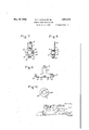
- Fig. 1 is a top view of one form of sheet metal stamped lever.
- Fig. 2 is a side view ofFig. 1, and
- Fig. 3. is a plan view of the sheet metal blank from which the lever shown in Figs. 1
- Fig. 4 is a top tion of the lever.
- Fig. 5 is a side view of the lever shown in Fig. 4, and V I Fig. 6 is a plan view of the sheet metal view of a slight modificastamping from-which the lever shown in first cut or stamped out of flat sheet metal.
- Said blank ha s ashank portion 1 and outwardly projecting'arms 1a and 1b extending from one end of the shank.
- the shan'k 1' is then bent at right angles to the arms, approximately along the dotted line 10, Fig. 3, to'bring the arms 1a, lb into parallelism, and the opposite arms are curved adjacent the shank, as at 1d to embrace a rod or tube that can be inserted between them; and the arms extend beyond these curved parts, forming ears whichjare provided with perforations 1e, lf for the passage of a fastening boltB and nut N (indicated in dotted lines in Figs.
- the lever can besecurely' clamped to a rod or tube.
- the outer end of the arm 1b is bent as shown in Fig 1 forming a limit stoplg to prevent excess ve compression or distortion of thearms.
- the shank 1 is preferably perforated a s'at lb for the attachment of a link or other device to operate the lever, or to be operated thereby, accordingto the connection in which the lever is used.
- the lever shown in Figs. 4 and 5 is made in a similar manner from an approximately Y-shaped blank, which has a shank, 1 and two spaced apart arms 1am and lbw these arms being parallel and connected with the shank byintegral sections 1 and 170.
- the arms 1am and lbw are bent' approximately along thedotted lineslkw and lie Fig. 6 atv right angles to the shank 1, which brings these arms. 1am and lbw into. spaced. apart pagallelism, like the arms lav-1b in Figs.-1 an 2.
- the inner surface of the curved portions M! can be serrated or roughened. indicated at 18 in Figs. .1, 3, .4c and 6, to 'increase the binding eifectof the arms on the rod or tube, but such levers can be tightly clamped to the rod or tube even Without such serrations, but the latter can be easily formed in the arms in the operation of stamping the blank from the sheet metal, and are useful when the leveris to beapplied to very hard and smooth finished rods or tubes. 7
- each of the levers is made by first stamping out of sheet metal a suitable blank, and then bending the blank so that the shank is at right angles to the arms.
- the shank forms the lever proper, and the two arms'form a clamp member on the end of the lever by which it may be fastened'to a rod or tube.
- Said arms are preferably perforated for the passage of an ordinary bolt by which the arms may be caused to rigidly clamp the-tube or rod.
- the 'length of the shanks can be readily varied according to the desired length of the actual operative portion of the lever, or the distance'it is desired to have such lever project from the tube or rod.
- the length of the arms of the blank can be varied in accordance 'With the diameter of the rod or tube with'which the lever is to be engaged.
- a stamped sheet metal lever comprising a shank portion and opposite arms bent at right angles to the shank portion, said arms extending in line with the shank portion and beyond the adjacent end thereof and adapted to embrace a rod or tube, and provided with means to prevent excessive closure of the 3 arms.
- a stamped sheet metal lever comprising a shank portion, opposite spaced arms bent at right angles to the shank portion and extending beyond the adjacent end of the shank portion and curved adjacent the shank to embrace a rod or tube, said arms also having perforations for engagement of clamping devices and-lugs to prevent excessive closure of the arms.
- Astamped sheet metal lever comprising a shank portion and opposite arms bent at right anglesto the shank portion and adapted to embrace a rod or tube, saidarms being provided with lugsfor engagement, With a Washer.
- a stamped sheet metal lever comprising a shank portion and opposite spaced arms bent at right angles to the shank portion and curved to embrace a rod or tube, said arms being 1 provided with lugs for engagement with a Washer, and extending beyond their curved parts for engagement of clamping devices.
- a stamped sheet metal lever comprising a shank portion and opposite armsbent at right angles to the shank portion and adapted to embrace a rod or tube, said arms being provided With lugs for engagement with a Washer, and provided with means to prevent excessive closure of the arms.
Landscapes
- Engineering & Computer Science (AREA)
- General Engineering & Computer Science (AREA)
- Mechanical Engineering (AREA)
- Clamps And Clips (AREA)
Description
y 10, 1932- M. F. STREBE ET AL 1,857,573
STAMPED SHEET METAL LEVER Filed July 9, 1928 2 Sheets-Sheet l May 10, l932- M. F. STREBE ET AL STAMPED SHEET METAL LEVER:
Filed July 9, 1928 2 Sheets-Sheet 2 Patented May 10, 1932 UNITED STATES Pare NT! OFFICE MELVILL E F. STR-EBE' AND CARROLL K. LENNINGg oF LA FAYETTE, INDIANA, AND
FRED W. ZINK OF DETROIT, MICHIGAN, ASSIGNORS TO ROSS GEAR & TOOL COM PANY, OF LA FAYETTE, INDIANA, A CORPORATION, INDIANA V i STAMPED SHEET-METAL LEVER j Application filed Llnly 9,
This invention is a novel improvement in sheet metal levers designed to be'attached to 'rods or tubesfor. the purpose of actuating same or being actuated thereby; and particularly in levers which are usable in automobile control assemblies to enable the spark ignition, choke, etc. to be controlled from and through the steering post. The invention enables levers to be stamped out of sheet metal, and yet made efiicient and provided with ample means for clamping same to a tube or rod, and in the accompanying drawingsv we have shown several forms of the levers, and methods of constructing same, and will explain the invention with reference to said drawings to enable others to adopt and use the invention; but it should be understood that the invention is not restricted to the specific forms illustrated as these can be varied within the scope of the invention according to the desired forms of the levers, and the purposes for which they areto be used. The essentials of the invention and novel features for which protection is desired are summarized in the claims.
In said drawings:
Fig. 1 is a top view of one form of sheet metal stamped lever.
Fig. 2 is a side view ofFig. 1, and
Fig. 3.is a plan view of the sheet metal blank from which the lever shown in Figs. 1
and 2 is formed. I
Fig. 4 is a top tion of the lever. I
Fig. 5 is a side view of the lever shown in Fig. 4, and V I Fig. 6 is a plan view of the sheet metal view of a slight modificastamping from-which the lever shown in first cut or stamped out of flat sheet metal.
192s. Serial No."2a1,410.
. Said blank ha s ashank portion 1 and outwardly projecting'arms 1a and 1b extending from one end of the shank. The shan'k 1' is then bent at right angles to the arms, approximately along the dotted line 10, Fig. 3, to'bring the arms 1a, lb into parallelism, and the opposite arms are curved adjacent the shank, as at 1d to embrace a rod or tube that can be inserted between them; and the arms extend beyond these curved parts, forming ears whichjare provided with perforations 1e, lf for the passage of a fastening boltB and nut N (indicated in dotted lines in Figs.
1 and) by'which the lever can besecurely' clamped to a rod or tube. ;Preferably; the outer end of the arm 1b is bent as shown in Fig 1 forming a limit stoplg to prevent excess ve compression or distortion of thearms. i
The shank 1 is preferably perforated a s'at lb for the attachment of a link or other device to operate the lever, or to be operated thereby, accordingto the connection in which the lever is used.
The lever shown in Figs. 4 and 5 is made in a similar manner from an approximately Y-shaped blank, which has a shank, 1 and two spaced apart arms 1am and lbw these arms being parallel and connected with the shank byintegral sections 1 and 170. i The arms 1am and lbw are bent' approximately along thedotted lineslkw and lie Fig. 6 atv right angles to the shank 1, which brings these arms. 1am and lbw into. spaced. apart pagallelism, like the arms lav-1b in Figs.-1 an 2.
Except for the difi'erences noted the lever shown in Figs. 4 and 5 is otherwise constructed similar to Figs-1 and 2, ;like partsbeingl.
similarly lettered and the parts ofthelever shown in Figs. 4 and 5 correspondingto the levers shown in Figs. 1 and 2 are similarly lettered, andas to these parts the description of one applies to both. In the construction shown in Figs. 7-10 the leveris constructed os' shown in Figs; 1 and 2 but the lug 1g is omitted and the arms 1a and 1b may beprovided on their edges with projecting lugs 1m which are adapted. to engage notches 2m in washers2 (which may be frictional Washers, or any other type) which it may, be desired v circumstances.
or on bothedges of the arm -as'indicated at 1m (and In in dotted lines in Fig- 8) If desired the inner surface of the curved portions M! can be serrated or roughened. indicated at 18 in Figs. .1, 3, .4c and 6, to 'increase the binding eifectof the arms on the rod or tube, but such levers can be tightly clamped to the rod or tube even Without such serrations, but the latter can be easily formed in the arms in the operation of stamping the blank from the sheet metal, and are useful when the leveris to beapplied to very hard and smooth finished rods or tubes. 7
Itwill be seen each of the levers is made by first stamping out of sheet metal a suitable blank, and then bending the blank so that the shank is at right angles to the arms. In each the shank forms the lever proper, and the two arms'form a clamp member on the end of the lever by which it may be fastened'to a rod or tube. Said arms are preferably perforated for the passage of an ordinary bolt by which the arms may be caused to rigidly clamp the-tube or rod. r a
r The 'length of the shanks can be readily varied according to the desired length of the actual operative portion of the lever, or the distance'it is desired to have such lever project from the tube or rod. The length of the arms of the blank can be varied in accordance 'With the diameter of the rod or tube with'which the lever is to be engaged. We do not'consider our invention limited to any of the specific forms herein shown, as the levers may be varied insize, relative proportions'of parts and appearance, ithin the scope of theinvention. 1
' jlVe claim 2- I a 1. A stamped sheet metal lever comprising a shank portion and opposite arms bent at right angles to the shank portion, said arms extending in line with the shank portion and beyond the adjacent end thereof and adapted to embrace a rod or tube, and provided with means to prevent excessive closure of the 3 arms.
2. A stamped sheet metal lever comprising a shank portion, opposite spaced arms bent at right angles to the shank portion and extending beyond the adjacent end of the shank portion and curved adjacent the shank to embrace a rod or tube, said arms also having perforations for engagement of clamping devices and-lugs to prevent excessive closure of the arms. I a
3. Astamped sheet metal lever comprising a shank portion and opposite arms bent at right anglesto the shank portion and adapted to embrace a rod or tube, saidarms being provided with lugsfor engagement, With a Washer.
4. A stamped sheet metal lever comprising a shank portion and opposite spaced arms bent at right angles to the shank portion and curved to embrace a rod or tube, said arms being 1 provided with lugs for engagement with a Washer, and extending beyond their curved parts for engagement of clamping devices.v
5. A stamped sheet metal lever comprising a shank portion and opposite armsbent at right angles to the shank portion and adapted to embrace a rod or tube, said arms being provided With lugs for engagement with a Washer, and provided with means to prevent excessive closure of the arms.
' M. F. STREBE. CARROLL K. LENNING; FRED WV. ZINK.
Priority Applications (1)
| Application Number | Priority Date | Filing Date | Title |
|---|---|---|---|
| US291410A US1857573A (en) | 1928-07-09 | 1928-07-09 | Stamped sheet-metal lever |
Applications Claiming Priority (1)
| Application Number | Priority Date | Filing Date | Title |
|---|---|---|---|
| US291410A US1857573A (en) | 1928-07-09 | 1928-07-09 | Stamped sheet-metal lever |
Publications (1)
| Publication Number | Publication Date |
|---|---|
| US1857573A true US1857573A (en) | 1932-05-10 |
Family
ID=23120179
Family Applications (1)
| Application Number | Title | Priority Date | Filing Date |
|---|---|---|---|
| US291410A Expired - Lifetime US1857573A (en) | 1928-07-09 | 1928-07-09 | Stamped sheet-metal lever |
Country Status (1)
| Country | Link |
|---|---|
| US (1) | US1857573A (en) |
Cited By (2)
| Publication number | Priority date | Publication date | Assignee | Title |
|---|---|---|---|---|
| US2505648A (en) * | 1945-11-05 | 1950-04-25 | Ewald F Pawsat | Steering post and method of manufacture |
| US3276586A (en) * | 1963-08-30 | 1966-10-04 | Rosaen Filter Co | Indicating means for fluid filters |
-
1928
- 1928-07-09 US US291410A patent/US1857573A/en not_active Expired - Lifetime
Cited By (2)
| Publication number | Priority date | Publication date | Assignee | Title |
|---|---|---|---|---|
| US2505648A (en) * | 1945-11-05 | 1950-04-25 | Ewald F Pawsat | Steering post and method of manufacture |
| US3276586A (en) * | 1963-08-30 | 1966-10-04 | Rosaen Filter Co | Indicating means for fluid filters |
Similar Documents
| Publication | Publication Date | Title |
|---|---|---|
| US2713186A (en) | Molding-anchorage device for securing trim-molding strips | |
| US2933970A (en) | U-shaped washers having retaining tabs | |
| US1857573A (en) | Stamped sheet-metal lever | |
| US1502133A (en) | Process of forming turnbuckles | |
| US1669934A (en) | Metallic collar and the like | |
| US3147832A (en) | Mounting means and tool therefor | |
| US1348767A (en) | Threadless rod or bolt | |
| US3254387A (en) | Pipe clamp lug with band gripping jaws | |
| US1628119A (en) | Safety lock for brake-rod pins | |
| US1641038A (en) | Rod clamp and clevis | |
| US1557099A (en) | Shaft and detachable gear | |
| US3253843A (en) | Clamp | |
| GB560526A (en) | Improvements relating to fastening devices for clamping articles together | |
| US1398122A (en) | Pedal-lock | |
| US1566377A (en) | Clamping device | |
| US2090167A (en) | Attaching clip for metal moldings | |
| US1735346A (en) | Band clip | |
| US894693A (en) | Nut-lock. | |
| US1698490A (en) | Control device | |
| DE1580436C3 (en) | Clutch release plate for motor vehicle friction disc clutches | |
| US1902569A (en) | Operating device | |
| US1242819A (en) | Extension attachment for automobile-pedals. | |
| US1605417A (en) | Brake-rod jaw | |
| US536934A (en) | Nut-lock | |
| US1598087A (en) | Belt-retaining hook |