US1856947A - Rotary engine - Google Patents
Rotary engine Download PDFInfo
- Publication number
- US1856947A US1856947A US274508A US27450828A US1856947A US 1856947 A US1856947 A US 1856947A US 274508 A US274508 A US 274508A US 27450828 A US27450828 A US 27450828A US 1856947 A US1856947 A US 1856947A
- Authority
- US
- United States
- Prior art keywords
- cylinders
- bearings
- pistons
- plates
- plate
- Prior art date
- Legal status (The legal status is an assumption and is not a legal conclusion. Google has not performed a legal analysis and makes no representation as to the accuracy of the status listed.)
- Expired - Lifetime
Links
- 210000000038 chest Anatomy 0.000 description 29
- 241000239290 Araneae Species 0.000 description 6
- 229910000906 Bronze Inorganic materials 0.000 description 4
- 239000010974 bronze Substances 0.000 description 4
- KUNSUQLRTQLHQQ-UHFFFAOYSA-N copper tin Chemical compound [Cu].[Sn] KUNSUQLRTQLHQQ-UHFFFAOYSA-N 0.000 description 4
- 230000007775 late Effects 0.000 description 4
- 229910000831 Steel Inorganic materials 0.000 description 3
- 239000012530 fluid Substances 0.000 description 3
- 239000000463 material Substances 0.000 description 3
- 239000010959 steel Substances 0.000 description 3
- 229910001018 Cast iron Inorganic materials 0.000 description 2
- 229910001361 White metal Inorganic materials 0.000 description 2
- 230000004888 barrier function Effects 0.000 description 2
- 239000010969 white metal Substances 0.000 description 2
- RYGMFSIKBFXOCR-UHFFFAOYSA-N Copper Chemical compound [Cu] RYGMFSIKBFXOCR-UHFFFAOYSA-N 0.000 description 1
- 208000029152 Small face Diseases 0.000 description 1
- 229910045601 alloy Inorganic materials 0.000 description 1
- 239000000956 alloy Substances 0.000 description 1
- 230000005540 biological transmission Effects 0.000 description 1
- 229910052802 copper Inorganic materials 0.000 description 1
- 239000010949 copper Substances 0.000 description 1
- 238000006073 displacement reaction Methods 0.000 description 1
- 239000010985 leather Substances 0.000 description 1
- 239000002184 metal Substances 0.000 description 1
- 229910052751 metal Inorganic materials 0.000 description 1
- 238000003466 welding Methods 0.000 description 1
Images
Classifications
-
- F—MECHANICAL ENGINEERING; LIGHTING; HEATING; WEAPONS; BLASTING
- F01—MACHINES OR ENGINES IN GENERAL; ENGINE PLANTS IN GENERAL; STEAM ENGINES
- F01B—MACHINES OR ENGINES, IN GENERAL OR OF POSITIVE-DISPLACEMENT TYPE, e.g. STEAM ENGINES
- F01B13/00—Reciprocating-piston machines or engines with rotating cylinders in order to obtain the reciprocating-piston motion
- F01B13/04—Reciprocating-piston machines or engines with rotating cylinders in order to obtain the reciprocating-piston motion with more than one cylinder
- F01B13/06—Reciprocating-piston machines or engines with rotating cylinders in order to obtain the reciprocating-piston motion with more than one cylinder in star arrangement
-
- F—MECHANICAL ENGINEERING; LIGHTING; HEATING; WEAPONS; BLASTING
- F03—MACHINES OR ENGINES FOR LIQUIDS; WIND, SPRING, OR WEIGHT MOTORS; PRODUCING MECHANICAL POWER OR A REACTIVE PROPULSIVE THRUST, NOT OTHERWISE PROVIDED FOR
- F03C—POSITIVE-DISPLACEMENT ENGINES DRIVEN BY LIQUIDS
- F03C1/00—Reciprocating-piston liquid engines
- F03C1/02—Reciprocating-piston liquid engines with multiple-cylinders, characterised by the number or arrangement of cylinders
- F03C1/04—Reciprocating-piston liquid engines with multiple-cylinders, characterised by the number or arrangement of cylinders with cylinders in star or fan arrangement
- F03C1/0403—Details, component parts specially adapted of such engines
- F03C1/0435—Particularities relating to the distribution members
Definitions
- the present invention is relative to a device with cylinders, the stroke volume of which can be modified, reversed or annulled during the working of the device or when it is stopping, the device comprising two centers of rotation and four cylinders.
- the present invention consists in substantial improvements in a rotary engine comprising spaced bearings, the one eccentric with relation to the other, a shaft journalled in eachfof said bearings, a rotary element supported by each of said shafts, said rotors be- 'ing arranged side by side and located between said bearings; said rotors are supporting cylinders, allsaid cylinders being arranged or rotation in the same plane; the pistons reciprocating in said cylinders are adapted to a floating spider element located between said rotors; the pistons are rigidly secured and maintained in fixed relation to one another by said floating spider element.
- the improvements consist in having one or both bearings movable with relation to each other, said bearings being used as distributing elements for the purpose of admission or exhaust, of. the cylinders.
- Fig. 1 is a front view of the device, a distribution chest and a bearing having been left out;
- Figs. 1 and 2 are similar views to Figs. 1 and 2, illustrating the device in a clearer and more diagrammatic manner;
- Fig. 4 is a horizontal section of a movable distribution box
- Figs. 5 and 6 are front and side views of the same chest
- Figs. 7 and 8 are front and'plan views, partially in section, of a xed distribution chest
- Fig. 9 is a side view'of the same chest.
- Figs. 10 to 13 illustrate diagrammatically the relative position of the several cylinders and their respective pistons at diierent cyclesy l of operation of the engine.
- 1, 1', 1" illustrate diagrammatically the relative position of the several cylinders and their respective pistons at diierent cyclesy l of operation of the engine.
- the four cylinders are all identical for what concerns their length and diameter; they are mountedv on the opposite ends of a diameter and at equal distance from the center of two rotary discs 3, 3', their axis be- M ing parallel to the diametral line of said plates.
- the space between plates 3, 3 depends on the .space occupied by the floating spider.
- the cylinders can be cast together with the plate 3, 3 or mounted so as to termv part with them.
- each cylinder Near the outer bottom of each cylinder is provided a port 5l.
- The, inner bottom of each cylinder provides tight passage for the piston rods formed by the arms of the spider'l 4; near said inner bottom of each cylinder is also provided a port 50.
- the plates comprise in their central portion, a projecting portion of conical shape and concentric with the shafts 31, 31'; the cavity comprisedinside said projecting portion is to be engaged by or to form part of a movable distribution chest, which will be described in detail hereafter.
- the two plates 3, 3' have their spindles 31, 31 in the same plane, either in alinement or parallel to each other and at a certain distance apart; said distance multiplied by two will give the stroke of the pistons in the cyl-l inders during the rotation of the device.
- the lates 3, 3 will be placed facing each other, t 1e spindles 31 extending towards the outside, in such a manner as to have the axes of cylinders'l and 1 and those of cylindersl l and 1 exactly in the same plane and intersecting at right angles. This posit ".on will be 'ven quite naturally b the intervention of t e cross member 4 whic will be hereafter described.
- the bearings 2 and 2 are ordinary bearings, in which tit, for turning purposes, the rotary spindles 31 in bearing 2 and 3l in bearing 2'; the rotation in the bearings can be operated by lubricated friction, by bear-- ing linings of bronze or other alloys, by ball bearings or any other means; bearing 2 is intended to support late 3 and bearing 2 to support plate 3', t e two ⁇ plates having no other su port than that of their rotary spindles in t e bearings.
- the axes of bearings 2 and 2 are in the same lane and either the one in alinement with tlhe other or at a certain distance from each other, in any direction whatever.
- a slide 90 has been contrived on the base 9 of said ibearings, the direction in which the slide moves being at right angles to the axes of the bearings.
- the slide 90 can for instance be moved by-means of a fixed but rotary mounted threaded spindle engaging the foot of the bearing by a corresponding threaded assage, said spindle beingr driven endwise y a crank and bevel wheel transmission.
- the bearings 2 and 2' have a prominent portion about their rotary axis, which fits in the cavity of the plates 3, 3 against the inner face of the centrai portion of said chassis lates, so as to prevent the latter from movmg backward.
- the outer periphery of. said portion will have the shape of a cone and will form the fixed distribution chest 7 cast together with the bearing 2 and which will be hereafter described.
- the cross-shaped member 4 generally made of very good steel can, under certain circumstances, be made of any other material suitable for the services for which it is intended. It has the shape of a rigid cross will follow the corresponding arm in all its ⁇ shiftings.
- the arms of the cross-shaped :nember 4 While serving as piston rod in each of the cylinders, the arms of the cross-shaped :nember 4, by their position at right angles to each other, maintain the axial line of the cylinders 1 and 1 perfectly at right angles to the axial line of cylinders 1 and 1', whenthe apparatus is working or stopping and maintain these axial lines in a plane at right angles to the axes of spindles 31 and 31.
- the pistons 5, 5', 5, 5 made of cast iron, i
- barsof the cross 4 can consist of screws, nuts, rivets, welding or any other appropriate means.
- Two fixed distribution chests 7 and 7 are made use of; they are cast in bronze orwhite metal, having to make a good joint while at y the same time to avoid a too hard friction.
- Each channel communicates by means of a lateral opening with a piping for the fluid inlet or outlet, such port or opening 60 being contrived inthe greater bank or radial side of the trapezoid; one of the channels is connected to the inlet piping, the other to the outlet piping.
- the section of the. channel of said chests 7, 7 will have to be suicient to give way to the quantities of iiuid necessary .to the admission or exhaust, without causing pinchings or constrictions.
- the chests 7 and 7 are to engage respectively in the fixed distribution chests 6 and 6.
- the movable distribution chests 6 and 6 have the shape of a conical ring, the cross section of which has the shape of a parallelogramme.
- This ring can be of steel, bronze, white metal or other material according to the needs, the thickness and height to be determined according to the opening surfaces of the fluid ports, to the surfaces forming joint and to the pressure efforts to which they are subjected.-
- the portions of the inner surface in contact withfixed chest 7 of said rings are perfectly polished on the edges of the small banks of the channel of chests 7 and 7, so as to form a smooth friction joint and to resist to the pressures.
- Ports 7 0 are contrived through the thickness othe rings 6 and 6', arranged at the opposite ends of a diameter of the ring and over a circumferential length to be determined by the opening and closing times of the inlet and outlet.
- the movable distribution chest 6 is to engage in the conical concave central portion of the plate 3, on the same side as the rotary spindle 31 and is secuged in such a manner as to form part and to turn integrally with the plate 3 about the xed chest 6 which forms joint withthe corresponding movable chest.
- the pipes 8, ⁇ 8', etc. connect the port of the movable distribution chest 6 with, at one end, the bottom of a cylinder, as shown at 50, and at the othenend vthe contrary bottom of the other cylinder mounted on the same plate, as shown at 51.
- the four pipes, mounted per pairs on each plate 3 operate thus the connection between the noncorresponding heads of two opposite cylinders mounted on the same plate.
- the base-frame 9 of the engine in cast iron, can have the shape of a frame outward- 1y surrounding the device or the shape of a ⁇ tray with an opening allowing the device, i. e. two complete plates 3, 3' and the crossshaped member It, to have the necessary roomv for rotating in their bearings without touching the frame 9.
- Two slides 90, alongwhich'the bearings 2 i I can slide, can be rovided on the frame 9, so
- the frame 9 can be made of two separate pieces allowing of the shift in g of bearings 2 which, in this case, can be fixed to the frame.
- the stroke volume is determined by multiplying the surface of the piston by the length of the stroke of the pistons in the cylinders.
- The. two chassis plates 3 and which rol tate with spindles 31 and 31 iirbearings 2 and 2 respectively, are indepelidentof each other and mounted on the base frame 9, so as to face each other and a certain distance apart from each other, so as to leave between them suiiicient space for the cross-shaped member 4.
- the rotary spindles 31', 31 dis osed towards the outside of the device an fitted in bearings 2 .and 2 mounted on the base frame.
- the device will 'then be at the dead center. In these conditions, the device can be rotated or a pressure can be introduced in the cylinders without causing the shifting of the pistons.
- bearings 2 could be shifted on slides 90 provided on the frame 9.
- the cylinders 1 and 1 have remained in the vertical position and the pistons 5 and 5 have remained at half stroke in the cylinders in which they move; these cylinders having remained in their position along with bearing 2, have-their axial line now nearer to cylinder 1" than to cylinder 1".
- pistons 5 and 'mounted in cylinders 1 and 1 and integral with cross-shaped member 4 have remained in their position without moving with respect to the cylinders 1 and 1', but that, cylinders-.1" and 1" having shifted with plate 3 to the left, pistons 5" and 5"' occupy a different position with relation to cylinders 1 and 1".
- the fixed distribution chest receiving the uids on one side, transmits these fluids through the channel of trapezoidal section and the passage port of the movable distribution chest to the pipings 8 and to the noncorresponding heads of two cylinders mounted on a same plate.V At the same time, the outletiluids are expelled on the other ride of the fixeddistribution chest after having passed through the piping, the passage port of movable chest 6 and the trapezoidal channel of chest 7.
- a rotary engine of the type set forth the combination of a frame, two spaced and parallel shafts, bearings for said shafts supported by and slidable on said frame, a rotary element at the end of each shaft and having opposite and coaxial cylinders, pistons in said cylinders, a floating spider intermediate the shafts and rigidly connecting all the pistons, an axially arranged distributing chamber in each bearing, an admission and an exhaust pipe ending in each distributing chamber.
Landscapes
- Engineering & Computer Science (AREA)
- Mechanical Engineering (AREA)
- General Engineering & Computer Science (AREA)
- Chemical & Material Sciences (AREA)
- Combustion & Propulsion (AREA)
- Reciprocating Pumps (AREA)
Description
F. D AUVRAIN l May 3, 1932.
ROTARY ENGINE Filed May 2, 1928 2 Sheets-Sheet May 3, 1932.
F. nAuvRAlN IROTARY ENGINE Filed May 2, 1928 2 Sheets-Sheet `2 jfagxf.
Patented May 3, 1932 UNITED STATES EBNAND `IDA'IJ'VRAIN', OF BRUSSELS, BELGIUM ROTARY ENGINE i Application 'iled Iay 2, 1928, Serial No. 274,508., and in Belgium May 6, 1927.
The present invention is relative to a device with cylinders, the stroke volume of which can be modified, reversed or annulled during the working of the device or when it is stopping, the device comprising two centers of rotation and four cylinders.
The present invention consists in substantial improvements in a rotary engine comprising spaced bearings, the one eccentric with relation to the other, a shaft journalled in eachfof said bearings, a rotary element supported by each of said shafts, said rotors be- 'ing arranged side by side and located between said bearings; said rotors are supporting cylinders, allsaid cylinders being arranged or rotation in the same plane; the pistons reciprocating in said cylinders are adapted to a floating spider element located between said rotors; the pistons are rigidly secured and maintained in fixed relation to one another by said floating spider element.
The improvements consist in having one or both bearings movable with relation to each other, said bearings being used as distributing elements for the purpose of admission or exhaust, of. the cylinders. i
The invention will be hereinafter described with reference to the accompanying-'drawings which illustrate, merely by way of an example, an embodiment of the same.
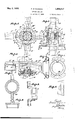
Fig. 1 is a front view of the device, a distribution chest and a bearing having been left out;
Figs. 1 and 2 are similar views to Figs. 1 and 2, illustrating the device in a clearer and more diagrammatic manner;
Fig. 2 is a side view, partially in section, of the. device; a Fig. 3 is a plan view of the device;
Fig. 4 is a horizontal section of a movable distribution box; Y p
Figs. 5 and 6 are front and side views of the same chest;
Figs. 7 and 8 are front and'plan views, partially in section, of a xed distribution chest;
Fig. 9 is a side view'of the same chest.
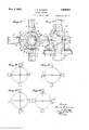
Figs. 10 to 13 illustrate diagrammatically the relative position of the several cylinders and their respective pistons at diierent cyclesy l of operation of the engine. With reference to these figures, 1, 1', 1"
and 1 indicate the four cylinders; 2 and 2 bearings; 3 and 3 the two rotary plates; 4 55.
a rigid spider; 5, 5, 5, 5 four pistons; 6
and 6 two rotating distribution chests; 7 and 7 two fixed distribution chests; 8, 8, 8" and 8 four distribution conduits giving connection with the cylinders; 9 a base plate.
The four cylinders are all identical for what concerns their length and diameter; they are mountedv on the opposite ends of a diameter and at equal distance from the center of two rotary discs 3, 3', their axis be- M ing parallel to the diametral line of said plates.
The space between plates 3, 3 depends on the .space occupied by the floating spider.
The cylinders can be cast together with the plate 3, 3 or mounted so as to termv part with them.
Near the outer bottom of each cylinder is provided a port 5l. The, inner bottom of each cylinder provides tight passage for the piston rods formed by the arms of the spider'l 4; near said inner bottom of each cylinder is also provided a port 50.
The rotation axes of the ' rotary plates 3, 3 cut at ri ht angles and at equal distance so `from the oy 'riders the axial line of the cylinders 1 and 1 and of cylinders 1" and 1, res eotively, the cylinders turning integrally wit the plates 3, 3 above the centers of the v plates. Si;
f: The Shafts of plates 3, 3 indicated at 31'- and 31' will be exactly perpendicular to the plane of said plates.
The plates comprise in their central portion, a projecting portion of conical shape and concentric with the shafts 31, 31'; the cavity comprisedinside said projecting portion is to be engaged by or to form part of a movable distribution chest, which will be described in detail hereafter. 95
Supported by the plates 3, 3 and outside the conical cavity of said plates, are mounted the connecting tubes 8 and 8 on plate 3 and the tubes 8 and 8 on the plate 3. These In conduits are connected approximately along inders. Rectangular ports 70 con rived through the wall ofv the conical Tportioii of the plates 3, 3', establish the connection between the movable distribution chests G, 6 which fits inside the conical cav1ty of chassis plate 3, and the inside of cham; 'bers 8. l
The two plates 3, 3' have their spindles 31, 31 in the same plane, either in alinement or parallel to each other and at a certain distance apart; said distance multiplied by two will give the stroke of the pistons in the cyl-l inders during the rotation of the device.
The lates 3, 3 will be placed facing each other, t 1e spindles 31 extending towards the outside, in such a manner as to have the axes of cylinders'l and 1 and those of cylindersl l and 1 exactly in the same plane and intersecting at right angles. This posit ".on will be 'ven quite naturally b the intervention of t e cross member 4 whic will be hereafter described.
The bearings 2 and 2 are ordinary bearings, in which tit, for turning purposes, the rotary spindles 31 in bearing 2 and 3l in bearing 2'; the rotation in the bearings can be operated by lubricated friction, by bear-- ing linings of bronze or other alloys, by ball bearings or any other means; bearing 2 is intended to support late 3 and bearing 2 to support plate 3', t e two` plates having no other su port than that of their rotary spindles in t e bearings.
The axes of bearings 2 and 2 are in the same lane and either the one in alinement with tlhe other or at a certain distance from each other, in any direction whatever. With a view of allowing the axes of bearings 2 and 2 to be brought nearer or farther apart or to be brought in alinement, a slide 90 has been contrived on the base 9 of said ibearings, the direction in which the slide moves being at right angles to the axes of the bearings. The slide 90 can for instance be moved by-means of a fixed but rotary mounted threaded spindle engaging the foot of the bearing by a corresponding threaded assage, said spindle beingr driven endwise y a crank and bevel wheel transmission.
The bearings 2 and 2' have a prominent portion about their rotary axis, which fits in the cavity of the plates 3, 3 against the inner face of the centrai portion of said chassis lates, so as to prevent the latter from movmg backward. The outer periphery of. said portion will have the shape of a cone and will form the fixed distribution chest 7 cast together with the bearing 2 and which will be hereafter described.
The cross-shaped member 4, generally made of very good steel can, under certain circumstances, be made of any other material suitable for the services for which it is intended. It has the shape of a rigid cross will follow the corresponding arm in all its` shiftings.
While serving as piston rod in each of the cylinders, the arms of the cross-shaped :nember 4, by their position at right angles to each other, maintain the axial line of the cylinders 1 and 1 perfectly at right angles to the axial line of cylinders 1 and 1', whenthe apparatus is working or stopping and maintain these axial lines in a plane at right angles to the axes of spindles 31 and 31. This is the principal function lof the cross-member 4 in the device.
The pistons 5, 5', 5, 5 made of cast iron, i
steel, copper, bronze, White metal, leather or other material which may be useful in certain circumstances, have, as a rule, the shape of regular cylinders, with or without rings; itmust be noticed, however, that any shape can be made use of,according to needs.
` The means of securing the pistons on the..
barsof the cross 4 can consist of screws, nuts, rivets, welding or any other appropriate means.'
The shifting of pistons 5 in cylinders 1 produces a volume which is determined by multiplying the surface of-piston 5 by the length of its displacement; this is the value that I call stroke volume. y
Two fixed distribution chests 7 and 7 are made use of; they are cast in bronze orwhite metal, having to make a good joint while at y the same time to avoid a too hard friction.
They have the shape of a ring, outwardly conical and inwardly cylindrical. The cross section of said ring forms a trapezoidal channel, the greater base of which is turned towards the outside of the ring and is disposed obliquely with relation to the small base, which forms the inner cylindrical portion of the ring; the two small faces of the trapezoid, at right angles to the above-mentioned bases, form the banks ofthe channel (Figs. 7 and 8) This channel is contrived all around the ring of chests 7, 7 but is completely interrupted in two places, arranged at the opposite endslof a diameter of the ring, by "a Atransverse dam or barrier, having a circumferential length to be determined by the closing and opening times of the inlet and outlet. These two dams or barriers leave thus in the ring of chests 7, 7 two channels i tribution chest 6, said joints resisting to the pressure efforts. v
Each channel communicates by means of a lateral opening with a piping for the fluid inlet or outlet, such port or opening 60 being contrived inthe greater bank or radial side of the trapezoid; one of the channels is connected to the inlet piping, the other to the outlet piping.
The section of the. channel of said chests 7, 7 will have to be suicient to give way to the quantities of iiuid necessary .to the admission or exhaust, without causing pinchings or constrictions.
`The chests 7 and 7 are to engage respectively in the fixed distribution chests 6 and 6.
Theselxed distribution chests 7, 7 consisting of a separate element or cast 'together with the bearings 2, 2', of which they completely surround the prominent portion, which is fitted in the conical cavity of the plates 3, 3', are mediums of the distribution device between the fixed portion and the movable portion of said device.
The movable distribution chests 6 and 6 have the shape of a conical ring, the cross section of which has the shape of a parallelogramme. This ring can be of steel, bronze, white metal or other material according to the needs, the thickness and height to be determined according to the opening surfaces of the fluid ports, to the surfaces forming joint and to the pressure efforts to which they are subjected.- The portions of the inner surface in contact withfixed chest 7 of said rings are perfectly polished on the edges of the small banks of the channel of chests 7 and 7, so as to form a smooth friction joint and to resist to the pressures.
Ports 7 0 are contrived through the thickness othe rings 6 and 6', arranged at the opposite ends of a diameter of the ring and over a circumferential length to be determined by the opening and closing times of the inlet and outlet.
The movable distribution chest 6 is to engage in the conical concave central portion of the plate 3, on the same side as the rotary spindle 31 and is secuged in such a manner as to form part and to turn integrally with the plate 3 about the xed chest 6 which forms joint withthe corresponding movable chest.
The pipes 8,` 8', etc., connect the port of the movable distribution chest 6 with, at one end, the bottom of a cylinder, as shown at 50, and at the othenend vthe contrary bottom of the other cylinder mounted on the same plate, as shown at 51. The four pipes, mounted per pairs on each plate 3 operate thus the connection between the noncorresponding heads of two opposite cylinders mounted on the same plate.
The base-frame 9 of the engine, in cast iron, can have the shape of a frame outward- 1y surrounding the device or the shape of a` tray with an opening allowing the device, i. e. two complete plates 3, 3' and the crossshaped member It, to have the necessary roomv for rotating in their bearings without touching the frame 9.
Two slides 90, alongwhich'the bearings 2 i I can slide, can be rovided on the frame 9, so
as to allow the dlstance between the parallel axes of the rotary spindles 314 to be altered.l If preferred, the frame 9 can be made of two separate pieces allowing of the shift in g of bearings 2 which, in this case, can be fixed to the frame.
The working of the device is as follows: the stroke volume is determined by multiplying the surface of the piston by the length of the stroke of the pistons in the cylinders.
The diameters of cylinders and pistons remain constant and for a same piston stroke, the stroke volume will always remain the same, but, in modifying the piston stroke, the stroke volume will also be modified,- that is to say that, for a reduction of the piston stroke, a reduction of the stroke volume will be obtained and conversely, for an increase:
fication that the modiiiable stroke volume,
obtained either during the working or when stopping in the above-describedl device, is
based. x
The. two chassis plates 3 and which rol tate with spindles 31 and 31 iirbearings 2 and 2 respectively, are indepelidentof each other and mounted on the base frame 9, so as to face each other and a certain distance apart from each other, so as to leave between them suiiicient space for the cross-shaped member 4. The rotary spindles 31', 31 dis osed towards the outside of the device an fitted in bearings 2 .and 2 mounted on the base frame.
lVhen these two plates have the axes of their spindles 31 and 31 in alinement of each other, the centenof the cross shaped member 4 will be on thisalinement, i. e. thfef-,two cen.
ters of the plates and the center lo'f the cross 4 willbe on the same straight line; the bearings 2 having their axis in alinement, the center of the cross-member 4 being o'n this axial line and the four cylinders being at equal distance from this line, and the our pistons being at half stroke intheir respective cylinders, the device will 'then be at the dead center. In these conditions, the device can be rotated or a pressure can be introduced in the cylinders without causing the shifting of the pistons.
It has been said that bearings 2 could be shifted on slides 90 provided on the frame 9.
Let us consider the frame 9 placed horizontally; the bearings 2 can then be shifted in a direction at right angles to their axes,.
inv part with the rotary spindles 31, 31' fitted in the bearings 2, 2 also to shift.
For a clear understanding, let us consider the device when stopped and let us look at it from the lett side, so as to see one of the bearings, 2', on the left hand side and the other bearing, 2, on the right hand'side, i. e. when placing ourselves on the left side of the device, we shall have the plate 3 on our right with its driving spindle 31 in the bearing 2, and the other plate 3' on our left with its driving spindle 31 in the bearing 2.
Considering the two cylinders 1 and 1', mounted on the plate 3, with their axis along the vertical line, the two'cylinders l" and 1"', mounted on the late 3', will be seen on end, since the cross-s aped member 4 places' the axial lines of each pair of cylinders at right angles to each other.
In the present conditions, if we shift the bearing 2'con our left hand side along its slide (without causing the device to turn), the spindle 31 maintained in said bearing will be shifted with it, as also the plate 3 and the cylinders 1" and 1"', in the same direction and along the same distance; pistons 5 and 5' have not followed this movement.
Let us now ass in front of the device and consider the ront elevation view. We see now, as a result of the shifting of bearing 2', which is behind the chassis plate 3 in the back ground and which is located on our left hand side, that the axes of spindles 31 and 31', which were in alinement, with the center of cross member 4 on said alinement, are now out of alinement, the axis of bearing 2 being to the right of that of bearing 2', and that the center of cross member 4 is no longer on the axis of bearing 2', but has remained on the axis of bearing 2.
The cylinders 1 and 1 have remained in the vertical position and the pistons 5 and 5 have remained at half stroke in the cylinders in which they move; these cylinders having remained in their position along with bearing 2, have-their axial line now nearer to cylinder 1" than to cylinder 1".
It will now be understood that pistons 5 and 'mounted in cylinders 1 and 1 and integral with cross-shaped member 4 have remained in their position without moving with respect to the cylinders 1 and 1', but that, cylinders-.1" and 1" having shifted with plate 3 to the left, pistons 5" and 5"' occupy a different position with relation to cylinders 1 and 1".
Suppose we have shifted the vbearing 2 3 cm. to the left, which would be its maximum shifting; in these conditions the pistons 5 and 5 of plate 3 have remained at halt` stroke between the heads of cylinders 1 and l', the axis of the latter having remained valong the vertical line.
The pistons 5" and 5"' of plate 3' although they have not moved, are brought 3 cm. to-
along the horizontal line, since the bearing 2', the plate 3 and the cylinders 1" and 1' have shifted 3 cm. towards the left.
Let us now rotate thechassis plates of a quarter revolution towards the left about their axes, i; e. not in a clockwise direction.
The cylinders 1 and 1' of plates 3 have now left the vertical position and their axial line now occupies a horizontal position (Fig. 11). The arms of cross-shaped member 4 fitted in cylinders 1 and 1 mounted on plate 3, have passed from the vertical to the horizontal position and the arms of cross-shaped member 4 mounted in cylinders 1" and 1"' of chassis plate 3' have passed with said cylinders 1" and 1"' to a vertical position.
For every quarter revolution of the device, the axial line of cylinders 1" and 1' will pass from the vertical to the horizontal, then from the horizontal tothe vertical position; the cross-shaped member 4, the bars of which are fitted in said cylinders, will follow these movements and move with them the plate 3 and the cylinders 1 and 1', which will thus also pass from the horizontal to the vertical and from the vertical to the horizontal for every quarter revolution (Figs. 10 to 13) It must be noticed that each time a pair of cylinders mounted on a plate asses with its axial line on the vertical line, by rotating about its rotation axis, the pistons mounted on the cross-shaped member 4 are at half stroke in said cylinders.
This position of the pistons at half stroke in the cylinders, when the axes of the latter pass along the vertical line, is given by the rigidness of cross-shaped member 4 which, having a bar fitted in every cylinder, keeps its center always on the intersection of the axiallines of said cylinders.
Let us now consider the four istons the one after the other starting from t c horizontal position, on the left of the spindles 31 and 31'; we shall notice then that at this moment they all start a stroke.
The fixed distribution chest receiving the uids on one side, transmits these fluids through the channel of trapezoidal section and the passage port of the movable distribution chest to the pipings 8 and to the noncorresponding heads of two cylinders mounted on a same plate.V At the same time, the outletiluids are expelled on the other ride of the fixeddistribution chest after having passed through the piping, the passage port of movable chest 6 and the trapezoidal channel of chest 7.
It has been said that the rotary spindles 31 and 31 could be placed apart from each other in any direction whatever, always keeping their axes parallel to each other. The results of this is that all the phases which have been described would be displaced in the same proportions if the spindles 31 and 31f were placed apart otherwise than in the horizontal plane.
From what has been described it Will be understood that the piston stroke can be adjusted by varying the distance between the rotary spindles. The movement of the pistons can even by inverted by inverting the relative positions of said rotary spindles.
I claim:
In a rotary engine of the type set forth, the combination of a frame, two spaced and parallel shafts, bearings for said shafts supported by and slidable on said frame, a rotary element at the end of each shaft and having opposite and coaxial cylinders, pistons in said cylinders, a floating spider intermediate the shafts and rigidly connecting all the pistons, an axially arranged distributing chamber in each bearing, an admission and an exhaust pipe ending in each distributing chamber. two distributing conduits on each rotary element, two diametrically opposed ports in the distributing chamber registering respectively with the distributing conduits, ports provided in the cylinders on either side ofthe piston and communicating respectively with the conduits ot the corresponding rotary element, the rear part of each cylinder communicating With the front part of the opposite cylinder.
In testimony whereof I signed hereunto my name.
F. DAUVRAIN.
Applications Claiming Priority (1)
| Application Number | Priority Date | Filing Date | Title |
|---|---|---|---|
| BE1856947X | 1927-05-06 |
Publications (1)
| Publication Number | Publication Date |
|---|---|
| US1856947A true US1856947A (en) | 1932-05-03 |
Family
ID=3895252
Family Applications (1)
| Application Number | Title | Priority Date | Filing Date |
|---|---|---|---|
| US274508A Expired - Lifetime US1856947A (en) | 1927-05-06 | 1928-05-02 | Rotary engine |
Country Status (1)
| Country | Link |
|---|---|
| US (1) | US1856947A (en) |
-
1928
- 1928-05-02 US US274508A patent/US1856947A/en not_active Expired - Lifetime
Similar Documents
| Publication | Publication Date | Title |
|---|---|---|
| US2972962A (en) | Hydraulic thrust bearing | |
| US1136363A (en) | Hydraulic transmission. | |
| US1910876A (en) | Rotary pump | |
| US1152729A (en) | Variable-stroke motor or pump. | |
| US2238252A (en) | Multiple plunger variable delivery pump | |
| US1856947A (en) | Rotary engine | |
| US2501998A (en) | Roto-volumetric pump | |
| US3369458A (en) | Hydraulic apparatus | |
| US924787A (en) | Variable-speed-transmission device. | |
| US1332516A (en) | Rotary pump | |
| US3036558A (en) | Wobble plate fluid motor and single valve means | |
| US1428876A (en) | Pump of variable capacity | |
| US2307719A (en) | Hydraulic pump construction | |
| US511044A (en) | cooper | |
| US2103474A (en) | Reversible planetary piston pump | |
| US1312962A (en) | Valveless pump | |
| US1794946A (en) | Hydraulic pump, motor, and the like | |
| US2889783A (en) | Pump or motor having four cylinders arranged in one plane | |
| US1678049A (en) | Fluid-control device | |
| US3180274A (en) | Silent variable delivery hydraulic pump | |
| US1240211A (en) | Pump. | |
| US1697924A (en) | Pump or hydraulic power-transmission machine | |
| US2663264A (en) | Rotary pump | |
| US2130298A (en) | Pump or motor | |
| US149059A (en) | Improvement in fluid-meters |