US1856835A - Power-transferring mechanism - Google Patents
Power-transferring mechanism Download PDFInfo
- Publication number
- US1856835A US1856835A US216769A US21676927A US1856835A US 1856835 A US1856835 A US 1856835A US 216769 A US216769 A US 216769A US 21676927 A US21676927 A US 21676927A US 1856835 A US1856835 A US 1856835A
- Authority
- US
- United States
- Prior art keywords
- shaft
- juice
- power
- housing
- head
- Prior art date
- Legal status (The legal status is an assumption and is not a legal conclusion. Google has not performed a legal analysis and makes no representation as to the accuracy of the status listed.)
- Expired - Lifetime
Links
- 230000007246 mechanism Effects 0.000 title description 19
- 235000011389 fruit/vegetable juice Nutrition 0.000 description 18
- 230000009471 action Effects 0.000 description 6
- 235000013399 edible fruits Nutrition 0.000 description 5
- 239000007788 liquid Substances 0.000 description 4
- 239000002253 acid Substances 0.000 description 2
- 150000007513 acids Chemical class 0.000 description 2
- 235000020971 citrus fruits Nutrition 0.000 description 2
- 230000000694 effects Effects 0.000 description 2
- 230000002093 peripheral effect Effects 0.000 description 2
- 229910000831 Steel Inorganic materials 0.000 description 1
- 102000004338 Transferrin Human genes 0.000 description 1
- 108090000901 Transferrin Proteins 0.000 description 1
- 208000027418 Wounds and injury Diseases 0.000 description 1
- 230000001413 cellular effect Effects 0.000 description 1
- 230000002596 correlated effect Effects 0.000 description 1
- 230000006378 damage Effects 0.000 description 1
- 238000000605 extraction Methods 0.000 description 1
- 235000015203 fruit juice Nutrition 0.000 description 1
- 239000011521 glass Substances 0.000 description 1
- 208000014674 injury Diseases 0.000 description 1
- 238000004519 manufacturing process Methods 0.000 description 1
- 235000013372 meat Nutrition 0.000 description 1
- 229910052751 metal Inorganic materials 0.000 description 1
- 239000002184 metal Substances 0.000 description 1
- 150000002739 metals Chemical class 0.000 description 1
- 238000000034 method Methods 0.000 description 1
- 238000003825 pressing Methods 0.000 description 1
- 230000008569 process Effects 0.000 description 1
- 239000010959 steel Substances 0.000 description 1
- -1 steel Chemical class 0.000 description 1
- 230000001954 sterilising effect Effects 0.000 description 1
- 239000012581 transferrin Substances 0.000 description 1
- 238000004804 winding Methods 0.000 description 1
Images

Classifications
-
- A—HUMAN NECESSITIES
- A47—FURNITURE; DOMESTIC ARTICLES OR APPLIANCES; COFFEE MILLS; SPICE MILLS; SUCTION CLEANERS IN GENERAL
- A47J—KITCHEN EQUIPMENT; COFFEE MILLS; SPICE MILLS; APPARATUS FOR MAKING BEVERAGES
- A47J19/00—Household machines for straining foodstuffs; Household implements for mashing or straining foodstuffs
- A47J19/02—Citrus fruit squeezers; Other fruit juice extracting devices
Definitions
- My invention relates to power-transferring mechanisms and means to 'be driven thereby. Notwithstanding the fact that 'I have brought about a new, novel, and useful combination of driving and driven mechanisms, respectively, that are suitable for a particular or very desirable. purpose, I do not wish to be limited as regards the urpose to which the invention is to be put, an therefore, the invention is essentially directed to new, novel and useful means whereby the transferring mechanism can be quickly correlated to the mechanism to be driven in ways that will effectively complete the powertransferring train between both of said mechanisms.
- my invention is directed to juice extractors for citrus fruits and has for one of its objects the provision of reliable means for preventing the metallic instrumentalities ofthe driven. motor from being attacked by the acids contained in the juice in the course of extraction.
- a further object resides in the provision of means for preventing loss of the juice during the extracting process and for conducting the extracted juice to a suitable receptacle.
- a further object of the invention is to provide means in conjunction with the juice extractor that will deliver the entrapped-juice to a place separate from the main point of discharge of the extracted juice.
- a further object of the invention is to provide a mechanism of this type which will be simple, light of weight, strong and durable and of a type that will be inexpensive of manufacture.
- a still furtherobject of the invention is to provide a mechanism of this type which is extremely compact.
- a still further object of the invention is to provide a power-transferring mechanism in eluding a shaft, the latter arranged in association with a fruit juice extractor of the type adapted to operate against the fruit when pressure of the hand is applied against the latter, and means for resisting the effect as of manual force applied against the power plant in line with the shaft during the extracting operation, thereby holding the entirety of working devices against sliding movement away from the operator.
- a still further object of the invention is to provide .a novel combination of mechanism of the character set forth in which the parts thereof can be knocked'down conveniently and subjected to a sterilizing or cleansing bath in order that they can be maintained in a sanitary condition.
- a still further object of the invention is to provide a novel form of strainer between the bowl of the extractor and the receptacle, into which latter the juice is adapted to be caught as it flows from the bowl.
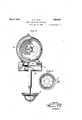
- Figure 1 is a view in side elevation, with parts in section and parts broken away, of a power-transferring mechanism in association with a driven mechanism;
- Figure 2 is a view partly in front elevation and partly in section
- Figure 3 is a section on line 3-3 of Figure 1;
- a power plant 10 which is preferably of the electrically operated type whose rotor shaft 11 extends to one side of the housing for the rotor.
- the shaft 11 is horizontally disposed, but it may be arranged at an angle to the horizontal by simply mounting the power plant at the angle selected.
- This housing is provided with elastic feet 13 adaptedto rest upon a counter or other suitable support A. Carried by the housing is a bracket 1 having a vertical flange adapted to come against the forward edge of the counter A where it will co-act therewith to resist .the action of: force when applied manually to the power plant 9' 4 axially of the shaft 11,hall for a purpose which will appear as e description continues.
- the bracket 14 carries an integral depending branch 15 which-threadedly accommodates'for vertical adjustment a shelf '16 having a drip bowl 17 and a plate or disk, the latter serving as a rest for a glass B or other receptacle.
- the power plant 10 is a power-transferring mechanism broadly, and secured to one face of the rotor housing is an annular support and centering means 18 for a hollow body 19 which encloses a driven mechanism.
- This driven mechanism may be a juice extractor fo'r citrus fruit, as illustrated, or I may elect to employ said power-transferring mechanism 1n association with other means to which power may be transferred for commercial purposes.
- the means 18 includes a head 20 through the center of which is extended the hexagonal end 21 of said shaft 11.
- the hollow body 19 comprises a collar 22 and a bowl 23, secured to the collar, and the means 18 removably accommodates the collar so that said means therefore centers the bowl with respect to the shaft 11 and so that the end 21 of the latter is axially positioned within the said bowl.
- the front of the bowl is formed with a large opening 24 which is designed to permitthe hand of the operator to enter therethrough and enable manual force to be applied against the fruit and effect its forced co-active presentation to the driven mechanism shown as a juice-extracting burr 25.
- This burr carries a hub 27 whose socket mates with the end of the shaft 11. I find that partly through the specific shapes of the shaft end 21 and the socket in the hub 27,
- the burr can be guided into position upon the shaft quickly and with great convenience.
- the collar 22 carries a forwardly extending hollow tube 28 which extends around the hub 27 in spaced relation thereto and completes the means for guiding the hub to its shaft-engagin position.
- the base 0 the bowl 23 is formed with a hollow depending branch 29-which serves as an outlet for the extracted juice, and, as shown, this branch r'emovably accommodates one or more expansive convolutions at the upper end of a substantially conical strainer 31, the same, in this instance, formed from a single piece of wire having its windings spaced apart from one another.
- This strainer has its apex positioned directly above the receptacle B so that the. flowing juice will be caught. thereby when the mechanism is in operation.
- the convolutions thereof can be expanded,.and cause their quick embracing connection with the branch 29.
- the acids contained in cit'-. rus fruits attack various metals, particularly steel, such as the bearings'of the power plant 10 and other essential parts thereof, and to avoid all possibilitisof injury incident to the action of such aci I employ the means 0 herein illustrated.
- the said means C consists of a bafile disk or centrifugal guard 32, the same secured to the shaft 11 at a point between the head 20 and the crown wall 33, the latter formed as part of the collar 22. This collar is spaced from the head 20 so that the two define a chamber D which communicates at 34 with the chamber E produced by the walls of the means 18.
- Said means 18 has an escape opening 35 so that as the juice caught by the disk 32 is thrown by centrifugal act1on into the chamber D, the same will finally take a course through the chamber E, thence through the opening 35.
- a ring 36 which functions the same as the disk 32. In this manner, I am able to trap all juice that flows along the shaft 11 and interrupt its flow before it has had an opportunity to elllter the casing of the aforementioned power p ant.
- the fruit from which the juice is to be extracted is held within the hand of the operator and applied with pressure against the burr 25 so as to break down cellular tissues of the meat of the fruit and thereby and by reason of induced suction cause the juice to be expelled into the bowl 23, where it is discharged into the receptacle B as it fl'ows from the strainer 31. Any juice that is expelled toward the shaft 11 is first and to some extent arrested by the tube 28.
- a motor having a power transferrin shaft rovided with a free extremity om w 'ch power may be distributed to' an object to be driven, a housing for said motor, an annular support secured to the housing of the motor and including a head through which said extremity of the shaft extends, the housing having an openin at a point below the ,longitudmal axis 0 the shaft through which liquidentering the housing is free to escape therefrom, and a disk carried by the shaft and positioned in advance of the aforementioned head, the head having an orifice positioned with respect to the peripheral edge of the disk so that liquid discharged from the disk by the action of centrifugal force will be directed to the orifice from which it ma find egress through the aforemention opening.
- a motor having a power transferring shaft rovided with a free extremity mm W ich power may be distributed to an object to be driven, a housing for said motor, an annular Y support secured to the housing of the motor and including a head through which said extremity of the shaft extends, the housing having an opening at a oint below the longitudinal axis of the she through which liquid entering the housin is free to escape therefrom, a disk carried by the shaft and positioned in advance of the aforementioned head, the head having an orifice positioned with respect to the peripheral edge of the disk so that liquid discharged from the disk by the action of centrifugal force will be directed to the orifice from which it may find egress through the aforementioned opening, and a ring embracing the shaft at a point inwardly of the said head and adapted to retard the flow of liquid along the shaft and to s5 discharge same by the action of centrifugal force in the direction of the said openin I DONA
Landscapes
- Engineering & Computer Science (AREA)
- Food Science & Technology (AREA)
- Food-Manufacturing Devices (AREA)
Description
May 3, 1932.
D s. HAYS POWER TRANSFERRING MECHANISM Filed Aug. 51.. 1927-; z 'sheets -sheejg ,"1-
' INVENTOR fllnah Q.
' ATTORNEYS May 3, 1932. D. s. HAYS POWER TRANSFERRING MEHANIsM 2 Sheets-Sheet 2 Filed Aug. 51. 1927 Emit-murmur INVENT'OR Donald 61%;,
ATTORNEYS Patented May 3, 1932 UNITED STATES PATENT OFFICE Application filed August 81, 1927. Serial No. 216,769.
My invention relates to power-transferring mechanisms and means to 'be driven thereby. Notwithstanding the fact that 'I have brought about a new, novel, and useful combination of driving and driven mechanisms, respectively, that are suitable for a particular or very desirable. purpose, I do not wish to be limited as regards the urpose to which the invention is to be put, an therefore, the invention is essentially directed to new, novel and useful means whereby the transferring mechanism can be quickly correlated to the mechanism to be driven in ways that will effectively complete the powertransferring train between both of said mechanisms.
More specifically, my invention is directed to juice extractors for citrus fruits and has for one of its objects the provision of reliable means for preventing the metallic instrumentalities ofthe driven. motor from being attacked by the acids contained in the juice in the course of extraction.
A further object resides in the provision of means for preventing loss of the juice during the extracting process and for conducting the extracted juice to a suitable receptacle.
A still further object of the invention is to provide a power=transferring shaft which oins a power plant with the juice-extracting urr, and means on the shaft operating as a bafiie or trap that will positively prevent the flow of the juice by capillary attraction or ofihefszwise beyond a certain point upon the s a A further object of the invention is to provide means in conjunction with the juice extractor that will deliver the entrapped-juice to a place separate from the main point of discharge of the extracted juice.
, A further object of the invention is to provide a mechanism of this type which will be simple, light of weight, strong and durable and of a type that will be inexpensive of manufacture.
A still furtherobject of the invention is to provide a mechanism of this type which is extremely compact.
A still further object of the invention is to provide a power-transferring mechanism in eluding a shaft, the latter arranged in association with a fruit juice extractor of the type adapted to operate against the fruit when pressure of the hand is applied against the latter, and means for resisting the effect as of manual force applied against the power plant in line with the shaft during the extracting operation, thereby holding the entirety of working devices against sliding movement away from the operator.
. A still further object of the invention is to provide .a novel combination of mechanism of the character set forth in which the parts thereof can be knocked'down conveniently and subjected to a sterilizing or cleansing bath in order that they can be maintained in a sanitary condition.
A still further object of the invention is to provide a novel form of strainer between the bowl of the extractor and the receptacle, into which latter the juice is adapted to be caught as it flows from the bowl.
Other objects and advantages will more fully appear as the description proceeds.
In the accompanying drawings, j
' Figure 1 is a view in side elevation, with parts in section and parts broken away, of a power-transferring mechanism in association with a driven mechanism;
Figure 2 is a view partly in front elevation and partly in section;
Figure 3 is a section on line 3-3 of Figure 1; and
4-4 of Fig- Figure' 4 is a sectionwon line are 1. a
In practice, useis made of a power plant 10 which is preferably of the electrically operated type whose rotor shaft 11 extends to one side of the housing for the rotor. In this instance, the shaft 11 is horizontally disposed, but it may be arranged at an angle to the horizontal by simply mounting the power plant at the angle selected. This housing is provided with elastic feet 13 adaptedto rest upon a counter or other suitable support A. Carried by the housing is a bracket 1 having a vertical flange adapted to come against the forward edge of the counter A where it will co-act therewith to resist .the action of: force when applied manually to the power plant 9' 4 axially of the shaft 11,hall for a purpose which will appear as e description continues. In the present example the bracket 14 carries an integral depending branch 15 which-threadedly accommodates'for vertical adjustment a shelf '16 having a drip bowl 17 and a plate or disk, the latter serving as a rest for a glass B or other receptacle.
The power plant 10 is a power-transferring mechanism broadly, and secured to one face of the rotor housing is an annular support and centering means 18 for a hollow body 19 which encloses a driven mechanism. This driven mechanism may be a juice extractor fo'r citrus fruit, as illustrated, or I may elect to employ said power-transferring mechanism 1n association with other means to which power may be transferred for commercial purposes. However, it will be appreciated that the means 18 includes a head 20 through the center of which is extended the hexagonal end 21 of said shaft 11.
The hollow body 19 comprises a collar 22 and a bowl 23, secured to the collar, and the means 18 removably accommodates the collar so that said means therefore centers the bowl with respect to the shaft 11 and so that the end 21 of the latter is axially positioned within the said bowl. The front of the bowl is formed with a large opening 24 which is designed to permitthe hand of the operator to enter therethrough and enable manual force to be applied against the fruit and effect its forced co-active presentation to the driven mechanism shown as a juice-extracting burr 25. This burr carries a hub 27 whose socket mates with the end of the shaft 11. I find that partly through the specific shapes of the shaft end 21 and the socket in the hub 27,
the burr can be guided into position upon the shaft quickly and with great convenience.
' The collar 22 carries a forwardly extending hollow tube 28 which extends around the hub 27 in spaced relation thereto and completes the means for guiding the hub to its shaft-engagin position.
The base 0 the bowl 23 is formed with a hollow depending branch 29-which serves as an outlet for the extracted juice, and, as shown, this branch r'emovably accommodates one or more expansive convolutions at the upper end of a substantially conical strainer 31, the same, in this instance, formed from a single piece of wire having its windings spaced apart from one another. This strainer has its apex positioned directly above the receptacle B so that the. flowing juice will be caught. thereby when the mechanism is in operation. By simply pressing against the diametrically opposlte sldes of thelarge end of the-strainer, the convolutions thereof can be expanded,.and cause their quick embracing connection with the branch 29.
It is known that the acids contained in cit'-. rus fruits attack various metals, particularly steel, such as the bearings'of the power plant 10 and other essential parts thereof, and to avoid all possibilitisof injury incident to the action of such aci I employ the means 0 herein illustrated. The said means C consists of a bafile disk or centrifugal guard 32, the same secured to the shaft 11 at a point between the head 20 and the crown wall 33, the latter formed as part of the collar 22. This collar is spaced from the head 20 so that the two define a chamber D which communicates at 34 with the chamber E produced by the walls of the means 18. Said means 18 has an escape opening 35 so that as the juice caught by the disk 32 is thrown by centrifugal act1on into the chamber D, the same will finally take a course through the chamber E, thence through the opening 35. To the rear of the head 20 and embracing-the shaft 11 is a ring 36 which functions the same as the disk 32. In this manner, I am able to trap all juice that flows along the shaft 11 and interrupt its flow before it has had an opportunity to elllter the casing of the aforementioned power p ant.
In operation, the fruit from which the juice is to be extracted is held within the hand of the operator and applied with pressure against the burr 25 so as to break down cellular tissues of the meat of the fruit and thereby and by reason of induced suction cause the juice to be expelled into the bowl 23, where it is discharged into the receptacle B as it fl'ows from the strainer 31. Any juice that is expelled toward the shaft 11 is first and to some extent arrested by the tube 28. Any juice that passes through the tube 28 finds exit at the centrifugal guard'32, which takes it up and distributes it by centrifugal force into the chamber D, and from this chamber the entrapped juice flows to the chamberE and finally escapes from the latter tionof the power plant, it will be caught by the ring and b the action of centrifu al force thrown there om into the chamber from which it is free to be expelled through the opening 35. 1 y
I claim as my invention:
1. In a device of the class described, a motor having a power transferrin shaft rovided with a free extremity om w 'ch power may be distributed to' an object to be driven, a housing for said motor, an annular support secured to the housing of the motor and including a head through which said extremity of the shaft extends, the housing having an openin at a point below the ,longitudmal axis 0 the shaft through which liquidentering the housing is free to escape therefrom, and a disk carried by the shaft and positioned in advance of the aforementioned head, the head having an orifice positioned with respect to the peripheral edge of the disk so that liquid discharged from the disk by the action of centrifugal force will be directed to the orifice from which it ma find egress through the aforemention opening. I
2. In a device of the class described, a motor having a power transferring shaft rovided with a free extremity mm W ich power may be distributed to an object to be driven, a housing for said motor, an annular Y support secured to the housing of the motor and including a head through which said extremity of the shaft extends, the housing having an opening at a oint below the longitudinal axis of the she through which liquid entering the housin is free to escape therefrom, a disk carried by the shaft and positioned in advance of the aforementioned head, the head having an orifice positioned with respect to the peripheral edge of the disk so that liquid discharged from the disk by the action of centrifugal force will be directed to the orifice from which it may find egress through the aforementioned opening, and a ring embracing the shaft at a point inwardly of the said head and adapted to retard the flow of liquid along the shaft and to s5 discharge same by the action of centrifugal force in the direction of the said openin I DONALD S. HAY
Priority Applications (1)
| Application Number | Priority Date | Filing Date | Title |
|---|---|---|---|
| US216769A US1856835A (en) | 1927-08-31 | 1927-08-31 | Power-transferring mechanism |
Applications Claiming Priority (1)
| Application Number | Priority Date | Filing Date | Title |
|---|---|---|---|
| US216769A US1856835A (en) | 1927-08-31 | 1927-08-31 | Power-transferring mechanism |
Publications (1)
| Publication Number | Publication Date |
|---|---|
| US1856835A true US1856835A (en) | 1932-05-03 |
Family
ID=22808435
Family Applications (1)
| Application Number | Title | Priority Date | Filing Date |
|---|---|---|---|
| US216769A Expired - Lifetime US1856835A (en) | 1927-08-31 | 1927-08-31 | Power-transferring mechanism |
Country Status (1)
| Country | Link |
|---|---|
| US (1) | US1856835A (en) |
Cited By (2)
| Publication number | Priority date | Publication date | Assignee | Title |
|---|---|---|---|---|
| US2655318A (en) * | 1950-06-29 | 1953-10-13 | Herbert G Beyer | Ice shaving machine |
| US4440074A (en) * | 1982-01-25 | 1984-04-03 | Tokyo Denki Kabushiki Kaisha | Juice extractor |
-
1927
- 1927-08-31 US US216769A patent/US1856835A/en not_active Expired - Lifetime
Cited By (2)
| Publication number | Priority date | Publication date | Assignee | Title |
|---|---|---|---|---|
| US2655318A (en) * | 1950-06-29 | 1953-10-13 | Herbert G Beyer | Ice shaving machine |
| US4440074A (en) * | 1982-01-25 | 1984-04-03 | Tokyo Denki Kabushiki Kaisha | Juice extractor |
Similar Documents
| Publication | Publication Date | Title |
|---|---|---|
| US1856835A (en) | Power-transferring mechanism | |
| US2930325A (en) | Elevated discharge sump pump | |
| GB639901A (en) | Improvements in or relating to suction cleaners | |
| NO144723B (en) | AVBOEYNINGSENHET. | |
| US1968515A (en) | Means for disposing of garbage | |
| GB983689A (en) | Vacuum separator | |
| US3203343A (en) | Juice extractor | |
| US1557620A (en) | Eyecup | |
| US1954105A (en) | Faucet connection | |
| US2057564A (en) | Fruit juice extractor | |
| US1855369A (en) | Preserve fruit squeezer | |
| US1871590A (en) | Apparatus for extracting juice from fruits | |
| CN112824511A (en) | Rose essential oil extraction equipment capable of improving extraction rate | |
| JPS5951325B2 (en) | Separation device | |
| US1981767A (en) | Propeller type air circulating fan | |
| US2679253A (en) | Apparatus for cleaning dishes prior to washing having means for separating tableware and garbage | |
| CN209577065U (en) | A kind of net newborn device of dairy products pretreatment using cavitation effect cleaning | |
| CN206934865U (en) | Chinese traditional medicine purification device | |
| US2705452A (en) | Fruit juicers | |
| US2228822A (en) | Juice extractor | |
| US1719132A (en) | Centrifugal apparatus | |
| GB1069606A (en) | Improvements in or relating to liquid cleaners | |
| US1661522A (en) | Fruit-juice extractor | |
| CN211462662U (en) | Gas-liquid separator for isobutyraldehyde processing | |
| US2006908A (en) | Sprayer |