US1856724A - Apparatus for making apertured pieces from strips of material - Google Patents
Apparatus for making apertured pieces from strips of material Download PDFInfo
- Publication number
- US1856724A US1856724A US452935A US45293530A US1856724A US 1856724 A US1856724 A US 1856724A US 452935 A US452935 A US 452935A US 45293530 A US45293530 A US 45293530A US 1856724 A US1856724 A US 1856724A
- Authority
- US
- United States
- Prior art keywords
- strip
- making
- block
- hole
- strips
- Prior art date
- Legal status (The legal status is an assumption and is not a legal conclusion. Google has not performed a legal analysis and makes no representation as to the accuracy of the status listed.)
- Expired - Lifetime
Links
- 239000000463 material Substances 0.000 title description 14
- 238000005520 cutting process Methods 0.000 description 8
- 238000010276 construction Methods 0.000 description 1
- 238000005553 drilling Methods 0.000 description 1
- 239000002184 metal Substances 0.000 description 1
- 238000000034 method Methods 0.000 description 1
- 238000000926 separation method Methods 0.000 description 1
Images
Classifications
-
- B—PERFORMING OPERATIONS; TRANSPORTING
- B21—MECHANICAL METAL-WORKING WITHOUT ESSENTIALLY REMOVING MATERIAL; PUNCHING METAL
- B21D—WORKING OR PROCESSING OF SHEET METAL OR METAL TUBES, RODS OR PROFILES WITHOUT ESSENTIALLY REMOVING MATERIAL; PUNCHING METAL
- B21D53/00—Making other particular articles
-
- B—PERFORMING OPERATIONS; TRANSPORTING
- B23—MACHINE TOOLS; METAL-WORKING NOT OTHERWISE PROVIDED FOR
- B23D—PLANING; SLOTTING; SHEARING; BROACHING; SAWING; FILING; SCRAPING; LIKE OPERATIONS FOR WORKING METAL BY REMOVING MATERIAL, NOT OTHERWISE PROVIDED FOR
- B23D45/00—Sawing machines or sawing devices with circular saw blades or with friction saw discs
- B23D45/02—Sawing machines or sawing devices with circular saw blades or with friction saw discs with a circular saw blade or the stock mounted on a carriage
-
- Y—GENERAL TAGGING OF NEW TECHNOLOGICAL DEVELOPMENTS; GENERAL TAGGING OF CROSS-SECTIONAL TECHNOLOGIES SPANNING OVER SEVERAL SECTIONS OF THE IPC; TECHNICAL SUBJECTS COVERED BY FORMER USPC CROSS-REFERENCE ART COLLECTIONS [XRACs] AND DIGESTS
- Y10—TECHNICAL SUBJECTS COVERED BY FORMER USPC
- Y10T—TECHNICAL SUBJECTS COVERED BY FORMER US CLASSIFICATION
- Y10T29/00—Metal working
- Y10T29/51—Plural diverse manufacturing apparatus including means for metal shaping or assembling
- Y10T29/5197—Multiple stations working strip material
Definitions
- This invention relates to apparatus for making holes in a strip of material and for cutting the strip between the holes so asto make articles, each of which is provided with a hole.
- this aim is accomplished by providing certain attachments to a punch press by means of which the hole making and strip cutting operations are performed.
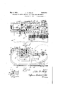
- Fig. 1 is a plan view of a machine em bodying the present invention and is partly in section taken on the line 11 of Fig. 2.
- Fig. 2 is a side elevation of the machine and is viewed in the direction of arrow 2 of Fig. 1 and is partly in section, the section being taken on the line 2--2 of Fig. 1.
- Fig. 2a is a fragmentary perspective View of a strip of material operated upon by the present machine.
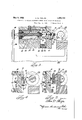
- Figs. 3, 4 and are fragmentary sectional views taken on lines 33, %4 and 5-5 respectively of Fig. 1 and are drawn to a larger scale than Figs. 1 and 2.
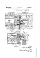
- Fig. 6 is a fragmentary sectional view taken on line 6-6 of Fig. 2 and is drawn to the same scale as Figs. 3, 4 and 5.
- Fig. 7 is a fragmentary sectional View on the line 7-7 of Fig. 6. i V
- the apparatus comprises a punch press having a frame supported in a horizontal position by a table 21.
- Frame 20 supports bearing 22 in which a crank shaft 23 is journalled having a crank 24 connected by connecting rod 25 with a cross head 26 which slides horizontally between ways 27 provided by the frame 20.
- the bed plate 30 of the punch press is shaped so as to provide an aperture 31 for receiving a cylindrical body 32 which is secured in place by a set 1930. Serial No. 452,935.
- the bed 30 guides for horizontal, sliding movement four screws 40 each threadedly connected with a work supporting block 4] which is yieldingly urged away from the bed 30 by springs 42 each surrounding a screw 40. Separation of the block 41 from the bed 30 is limited by the head 43 of each screw striking an annular shoulder 44 provided by the bed 30.
- the block 41 is provided with a groove 45 for receiving a hard metal wear piece 46 which is shaped so as to guide the work. Since the disclosed embodiment of the present invention is particularly adapted to operate upon a material strip A having flanges B and C meeting at right angles, the wear piece 46 is provided with a groove 47 for receiving the flange C. The flange B slides along the outer surface of the wear piece 46.
- the strip A is fed into the machine until the end in the machine engages a stop screw 50 which is threadedly adjustable through a so block 51 attached in any suitable manner to the block 41.
- the cutting operation is performed by a rotary cutter or saw carried by shaft 71 journalled in a bearing bracket 7 2 attached to the cross head 26 and carrying a pulley 73 which receives a driving belt 7 4 operating in any suitable manner as by an electric motor (not shown).
- the method of operating the machine is as follows:
- the punch press head 26 operates continuously. During movement of the head 26 toward the right as viewed in the drawings, the operator pushes the strip A against the inner end of the stop screw 50 and holds it in that position while the head 26 moves toward the left.
- the first thing that happens during movement of the head 26 toward theleft is that the pressure block 52 is caused to clamp the work between the block 52 and the wear piece 46.
- the drill 39 is caused to drill through the strip A in order to form a hole 90.
- the saw 70 cuts away the material between the lines abc and def thereby cutting from the strip A an article D having a hole 90 in its flange B, said hole 90 having been formed in the preceding operation of the machine.
- the piece D has been severed from the strip A it is thrown downwardly as indicated at D in Fig. 4 due to the rotation of the'saw in a counterclockwise direction as indicated by the arrows 91.
- Apparatus for making apertured pieces from a strip of material comprising in combination, a strip holder, a hole making means located on one side of the strip holder, a rotary saw located on the other side of the strip holder, and means for causing relative movements to take place between the strip holder and saw and between the strip holder and hole making means in order that the saw and hole making means may operate upon the strip.
- Apparatus for making apertured pieces from a strip of material comprising in combination, a strip holder, hole making means and strip cutting means located respectively on opposite sides of the strip holder, and mechanism for causing the strip cutter to engage the strip and the strip holder to move toward the hole making means.
- Apparatus for making apertured pieces from a strip of material comprising, in combination, a hole making tool and a support therefor, a strip holder mounted on the support and guided for lateral movement relative to the support, a reciprocating member movable toward the strip holder and toolsupport and away from them, a strip cutter carried by the member, and means for causing the cutter to engage the strip and the member to engage the strip holder and to move the strip holder toward the hole making tool.
- Apparatus for making apertured pieces from a. strip of material comprising in combination, a strip holder, a drill locatedon one side of the strip holder, a rotary saw located on the opposite side of the strip holder, and means for causing relative movement between the rotary saw and the strip holder, and means for causing relative movement between the saw and strip holder so moved and the drill.
- Apparatus for making apertured pieces from a strip of material comprising in combination, a strip holder, hole making means located on one side of said strip holder, strip cutting means located on the. opposite side of a strip holder, and means for causing relative movement to take place between the strip holder and strip cutting means, and thence concurrent movement 7 of the strip holder means and strip cutting means relative to the hole making means.
Landscapes
- Engineering & Computer Science (AREA)
- Mechanical Engineering (AREA)
- Perforating, Stamping-Out Or Severing By Means Other Than Cutting (AREA)
Description
y 1932. A. w. PHELPS l;856,724
APPARATUS FOR MAKING APERTURED PIECES FROM STRIPS OF MATERIAL Filed May 16, 1930 3 Sheets-Sheet l A. W. PH ELPS May 3, 1932.
APPARATUS FOR MAKING APERTURED PIECES FROM STRIPS OF MATERIAL Filed May 16, 1930 3 Sheets-Sheet 2 3/ 5a 30 35 La o 4240 4/ A. W. PHELPS APPARATUS FOR MAKING APERTURED PIECES FROM STRIPS OF MATERIAL 3 Sheets-Sheet 5 Filed May 1 1930 E 42 4a 41 57 5O .75 M I 81 072 0 W4 6"; I 70 v I 55 :9 Id 65 ,7 6 I p Patented May 3, 1932 UNITED STATES PATENT OFFICE ALVA W. PHELPS, OF ANDERSON, INDIANA, ASSIGNOR T DELCO-REMY CORPORATION,
OF ANDERSON, INDIANA, A CORPORATION OF DELAWARE APPARATUS FOR MAKING APERTURED PIECES FROM STRIPS 0F MATERIAL Application filed May 16,
This invention relates to apparatus for making holes in a strip of material and for cutting the strip between the holes so asto make articles, each of which is provided with a hole.
It is an object of the present invention to provide a machine which is simple in construction and which can be produced at low cost. In the disclosed embodiment of the invention, this aim is accomplished by providing certain attachments to a punch press by means of which the hole making and strip cutting operations are performed.
Further objects and advantages of the present invention will be apparent from the following description, reference being had to the accompanying drawings wherein a preferred embodiment of one form of the present invention is clearly shown.
In the drawings:
Fig. 1 is a plan view of a machine em bodying the present invention and is partly in section taken on the line 11 of Fig. 2.
Fig. 2 is a side elevation of the machine and is viewed in the direction of arrow 2 of Fig. 1 and is partly in section, the section being taken on the line 2--2 of Fig. 1.
Fig. 2a is a fragmentary perspective View of a strip of material operated upon by the present machine.
Figs. 3, 4 and are fragmentary sectional views taken on lines 33, %4 and 5-5 respectively of Fig. 1 and are drawn to a larger scale than Figs. 1 and 2.
Fig. 6 is a fragmentary sectional view taken on line 6-6 of Fig. 2 and is drawn to the same scale as Figs. 3, 4 and 5.
Fig. 7 is a fragmentary sectional View on the line 7-7 of Fig. 6. i V
The apparatus comprises a punch press having a frame supported in a horizontal position by a table 21. Frame 20 supports bearing 22 in which a crank shaft 23 is journalled having a crank 24 connected by connecting rod 25 with a cross head 26 which slides horizontally between ways 27 provided by the frame 20. The bed plate 30 of the punch press is shaped so as to provide an aperture 31 for receiving a cylindrical body 32 which is secured in place by a set 1930. Serial No. 452,935.
The bed 30 guides for horizontal, sliding movement four screws 40 each threadedly connected with a work supporting block 4] which is yieldingly urged away from the bed 30 by springs 42 each surrounding a screw 40. Separation of the block 41 from the bed 30 is limited by the head 43 of each screw striking an annular shoulder 44 provided by the bed 30. The block 41 is provided with a groove 45 for receiving a hard metal wear piece 46 which is shaped so as to guide the work. Since the disclosed embodiment of the present invention is particularly adapted to operate upon a material strip A having flanges B and C meeting at right angles, the wear piece 46 is provided with a groove 47 for receiving the flange C. The flange B slides along the outer surface of the wear piece 46. The strip A is fed into the machine until the end in the machine engages a stop screw 50 which is threadedly adjustable through a so block 51 attached in any suitable manner to the block 41.
While the strip A isbeing operated upon it is clamped against the wear piece 46 by a pressure block 52 supported by bolts 53 which are received by holes 54' provided by a bracket 55 integral with the cross head 26 of the punch press. Springs 56 each surrounding a bolt 53 tend to urge the pressure block 52 away from the bracket 55 until the 99 heads of the boltsengage a surface of the bracket. The drilling operation upon the strip A is performed by the drill 39 which is received by. a hole 60 in the block 41 and is guided by a busl'ling 61 press fitted into the block 41. The drill 39 is located so as to be received by a hole 62 in the wear piece 46 and by a hole 63 in the pressure block 52, said hole 63 being in alignment with the hole 62. I
LOG
The cutting operation is performed by a rotary cutter or saw carried by shaft 71 journalled in a bearing bracket 7 2 attached to the cross head 26 and carrying a pulley 73 which receives a driving belt 7 4 operating in any suitable manner as by an electric motor (not shown).
The method of operating the machine is as follows: The punch press head 26 operates continuously. During movement of the head 26 toward the right as viewed in the drawings, the operator pushes the strip A against the inner end of the stop screw 50 and holds it in that position while the head 26 moves toward the left. The first thing that happens during movement of the head 26 toward theleft is that the pressure block 52 is caused to clamp the work between the block 52 and the wear piece 46. During further movement of the head 26 toward the moves toward the left untilit strikes a block 80 attached to the block 41, and at the same time the bracket 72 strikes the head of a screw 81 threaded through the block 4 1 and locked in adjusted position by lock nuts 82 in order that the distance between the head of the screw 81 and the bracket 7 2 will be equal to the distance between the block 80 and the adjacent surface of the cross head 26. After the cross head 26 has engaged the block 80, and the bracket 7 2 thescrew 81, the parts 26, 52 and, 41 will move together toward the left. lVhile the bracket 72 is moving toward the left relative to the work supporting block 71, the saw 70 operates to sever that portion of the strip lying between the saw and the stop screw 50. During movement of the block 41 toward the bed 30 the drill 39 is caused to drill through the strip A in order to form a hole 90. Referring to Fig. 2a, the saw 70 cuts away the material between the lines abc and def thereby cutting from the strip A an article D having a hole 90 in its flange B, said hole 90 having been formed in the preceding operation of the machine. As soon as the piece D has been severed from the strip A it is thrown downwardly as indicated at D in Fig. 4 due to the rotation of the'saw in a counterclockwise direction as indicated by the arrows 91.
While the form of embodiment of the present invention as herein disclosed, constitutes a preferred form, it is to be understood that other forms might be adopted, all coming within the scope of the claims which follow.
What is claimed is as follows:
1. Apparatus for making apertured pieces from a strip of material comprising in combination, a strip holder, a hole making means located on one side of the strip holder, a rotary saw located on the other side of the strip holder, and means for causing relative movements to take place between the strip holder and saw and between the strip holder and hole making means in order that the saw and hole making means may operate upon the strip.
2. Apparatus for making apertured pieces from a strip of material comprising in combination, a strip holder, hole making means and strip cutting means located respectively on opposite sides of the strip holder, and mechanism for causing the strip cutter to engage the strip and the strip holder to move toward the hole making means.
3. Apparatus for making apertured pieces from a strip of material, comprising, in combination, a hole making tool and a support therefor, a strip holder mounted on the support and guided for lateral movement relative to the support, a reciprocating member movable toward the strip holder and toolsupport and away from them, a strip cutter carried by the member, and means for causing the cutter to engage the strip and the member to engage the strip holder and to move the strip holder toward the hole making tool.
4. Apparatus according to claim 3 in which the reciprocating member carries a clamp which is spring urged against the strip while the reciprocating member is moving the strip holder toward the hole-making tool.
5. Apparatus for making apertured pieces from a. strip of material comprising in combination, a strip holder, a drill locatedon one side of the strip holder, a rotary saw located on the opposite side of the strip holder, and means for causing relative movement between the rotary saw and the strip holder, and means for causing relative movement between the saw and strip holder so moved and the drill.
, 6. Apparatus for making apertured pieces from a strip of material comprising in combination, a strip holder, hole making means located on one side of said strip holder, strip cutting means located on the. opposite side of a strip holder, and means for causing relative movement to take place between the strip holder and strip cutting means, and thence concurrent movement 7 of the strip holder means and strip cutting means relative to the hole making means.
In testimony whereof I hereto aiiix my signature. I
ALVA 1V. PHELPS.
Priority Applications (1)
| Application Number | Priority Date | Filing Date | Title |
|---|---|---|---|
| US452935A US1856724A (en) | 1930-05-16 | 1930-05-16 | Apparatus for making apertured pieces from strips of material |
Applications Claiming Priority (1)
| Application Number | Priority Date | Filing Date | Title |
|---|---|---|---|
| US452935A US1856724A (en) | 1930-05-16 | 1930-05-16 | Apparatus for making apertured pieces from strips of material |
Publications (1)
| Publication Number | Publication Date |
|---|---|
| US1856724A true US1856724A (en) | 1932-05-03 |
Family
ID=23798564
Family Applications (1)
| Application Number | Title | Priority Date | Filing Date |
|---|---|---|---|
| US452935A Expired - Lifetime US1856724A (en) | 1930-05-16 | 1930-05-16 | Apparatus for making apertured pieces from strips of material |
Country Status (1)
| Country | Link |
|---|---|
| US (1) | US1856724A (en) |
Cited By (1)
| Publication number | Priority date | Publication date | Assignee | Title |
|---|---|---|---|---|
| US3178667A (en) * | 1962-07-13 | 1965-04-13 | Morse Milton | Manually releasable grounding electrical plug |
-
1930
- 1930-05-16 US US452935A patent/US1856724A/en not_active Expired - Lifetime
Cited By (1)
| Publication number | Priority date | Publication date | Assignee | Title |
|---|---|---|---|---|
| US3178667A (en) * | 1962-07-13 | 1965-04-13 | Morse Milton | Manually releasable grounding electrical plug |
Similar Documents
| Publication | Publication Date | Title |
|---|---|---|
| USRE30025E (en) | Universal double cut die set | |
| CN104589061A (en) | Bar part cutting and drilling integrated machine | |
| US4143571A (en) | Assemblies for workpiece positioning | |
| CN105729125A (en) | Strip steel punching and shearing line | |
| CN204235126U (en) | Brill machining center cut by rod class part | |
| US2071201A (en) | Workshop unit | |
| US2230292A (en) | Machine tool | |
| US1856724A (en) | Apparatus for making apertured pieces from strips of material | |
| KR20170111016A (en) | Tap-working apparatus for a long shaft with solid section | |
| US2404149A (en) | Contouring machine | |
| US3481236A (en) | Means for guiding the punch in nibbling machines and the like | |
| CN212682549U (en) | A horizontal milling machine | |
| CN109719329A (en) | A kind of slotter for elongated shaft milling through slot | |
| CN206588683U (en) | A kind of blanking bullet of automatic gas cutting machine send device and cutting structure | |
| US3459104A (en) | Router attachment apparatus | |
| CN210614805U (en) | Automatic feeding punching and shearing machine | |
| US2266847A (en) | Power driven ripsaw | |
| CN215467646U (en) | Feeding device suitable for straight knife and arc knife | |
| CN210677055U (en) | Drilling machine for workpiece machining | |
| US874183A (en) | Power-punch. | |
| CN111300054B (en) | Workpiece punching and turning-milling all-in-one machine | |
| US2615483A (en) | Shaper-saw power feed device | |
| SU950185A3 (en) | Device for bevel cutting of workpieces | |
| CN110919389A (en) | Multifunctional angle steel processing all-in-one machine | |
| US782238A (en) | Steady-rest for metal-working machines. |