US1856494A - Hair waving device - Google Patents
Hair waving device Download PDFInfo
- Publication number
- US1856494A US1856494A US488882A US48888230A US1856494A US 1856494 A US1856494 A US 1856494A US 488882 A US488882 A US 488882A US 48888230 A US48888230 A US 48888230A US 1856494 A US1856494 A US 1856494A
- Authority
- US
- United States
- Prior art keywords
- hair
- leg
- pin
- heaters
- wound
- Prior art date
- Legal status (The legal status is an assumption and is not a legal conclusion. Google has not performed a legal analysis and makes no representation as to the accuracy of the status listed.)
- Expired - Lifetime
Links
Images
Classifications
-
- A—HUMAN NECESSITIES
- A45—HAND OR TRAVELLING ARTICLES
- A45D—HAIRDRESSING OR SHAVING EQUIPMENT; EQUIPMENT FOR COSMETICS OR COSMETIC TREATMENTS, e.g. FOR MANICURING OR PEDICURING
- A45D4/00—Separate devices designed for heating hair curlers or hair-wavers
- A45D4/08—Separate devices designed for heating hair curlers or hair-wavers for flat curling, e.g. with means for decreasing the heat
- A45D4/12—Separate devices designed for heating hair curlers or hair-wavers for flat curling, e.g. with means for decreasing the heat heated by electricity
Definitions
- My invention relates to curling hair and has for its object to provide a new and efficient device for curling the hair in a permanent wave.
- a further object is to provide a permanent waving machine which will place a wave in the hair which is more natural than the usual wave and which wave will hold the curl in the hair longer and more permanently than any 19 wave heretofore used.
- a still further object is to provide a per manent wave which when placed in the hair will not need to be set by water waving or other similar means but which wave will re- 15 main in the hair until the hair has grown out and is cut oif.
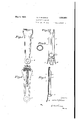
- Figure 1 is a plan view of the heater element.
- Figure 2 is a side elevation thereof.
- Figure 8 is a section on line 33 of Figure 2.
- Figure 4 is a. section of the 7 heating elements with the hair shown wound onthe pin and with the hair pin and protector shown in elevation.
- Figure 5 is a section on line Jr-4 of Figure 1, sectioning only one heater.
- Figure 6 is a plan view of a heat transmitter used around the pin when separate 'heatings are used.
- Figure 7 is a side elevation of the separateheaters used on the heat transmitter with the pin, hair and protector shown used therewith.
- Figure 8 is a side elevation of the heat transmitter.
- Figure'9 is a section on line 9-9 of Figure 10.
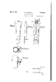
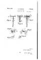
- Figure lO is a plan view of the heaters.
- Figure 11 is a. plan view ofthe hair winding pin.
- Figure; 12 is a'vertical section of the pins.
- Figure 13 is a section of'a modified form of constructing the pins.
- Figure 1 1 is a plan view of the protector used with the device.
- Figure 15 is an end view thereof.
- Figure 16 is a section on line 16-16 of Figure 14:.
- Figure 17 is a plan view of the protector shown partially opened.
- the heater A is made in two hingedly connected members 1 and 2, hinged together by a hinge, and held normally closed by the spring, with handles 4a to open and close the elements.
- the inner face of the two heaters 1 and 2 is curved to fit the outer surface of a heat transmitting member 5.
- Each heater is provided with a heating electrical element B formed therein and connected with a source of. electrical energy by wires B1 and B2.
- the transmitters 5 are formed of two curved sheets of metal formed as shown in the drawings with a cross area and a leg area joined together by a curved area.
- the two transmitters 5 are hingedly connected together by the hinge 6 and handles are extended back from the outer sides of each heater by which they may be opened when placing them on the hair.
- the other type of heaters designated as C are made of two pieces of sheet metal 9 and 10 secured together by crimping the inner face 10 around the edges of the sheet 9. Insulation is placed within the space between the two sheets of metal and a heating element 11 is carried therein to heat the heaters.
- WVires 12 and 13 connect the elements with a source of electrical energy.
- hinge 14 connects the two heaters together and handles 15 extended from the sheets of metal 9 provide means of opening the heaters to allow them to be placed around the hair.
- a spring 15 holds the two heaters normally closed.
- the said spring is wound around 9 the pivot pin 16 of the hinge 1 1.
- the pin on which the hair is wound is designated as D and is made in a T-shape having the top or cross 18 of the T formed with the walls thereof concave or curved inwardly toward the medial portion and a bore 19 is formed medially of the cross 18 in which a holding bolt 20 is secured.
- a larger bore 21 is formed in the top 18 around the bolt 20, and the leg i -23 ofthe pinis carried around the bolt with one end inserted into said bore 21.
- the end i 24 of the leg 23 is formed with teeth 25 therearound adapted to be engaged by a dog 26 which. dog is carried in a hole 27 said hole.
- the dog '26. and the teeth are formed so thatthe leg maybe rotated in only one direction.
- the end of the leg 23 is formed with a larger hole to allow the head of the bolt 20 to be retained therein and the outer end of the hole is threaded to receive a tapered extension leg 33 said leg having the outer'diameter of the large end the same diameter as the end of the leg 23.
- the leg 33 is tapered toward the lower end and the extreme end is formed'either hexagonal or square to allow a wrench to. be placed thereon so that the entire combination leg 25 may be rotated by turningthe end of the leg 33.
- the combination leg 34 is composed of the two legs 23 and 33 when secured together.
- the ends of'the bar 18 are slotted at 18a toprovide means to lock the pins vertical;
- the modified form of pin shown in Figure13 is made with the cross top 33 bored with a medial two diameteredhole 36 withabolt 37 screwed into the smaller bore and with one end of a v leg-38 carried in the-larger bore 11.
- the leg'28 is centrally bored to surround the bolt 45 37 and the outer end of the bore 'is'enlarged to'form a hole 39 in which the head-of the .bolt37 is carried.
- the central bore of the I leg ismade larger near the endwhich is inserted into the top 35 and a springAO is 'carriedtherein' to normallyhold the leg spacedfrom the end of thelarger bore 41.
- the end oftheibore or-hole 39 is formed as I teeth '42 andthe under sidej of the head 15 I ofthe bolt 37 is formed into teeth 43 with the i teeth 42 to engage the teeth 43 and adapted to allow the leg 38 to berotated therearound in one-direction and'prevent rotation in the opposite direction.
- Theend of the leg may be formed'hexagonal' to allow a 'wrench tobe placed thereon to'rotate the leg or it may T be'made as shown in the drawings with the end of the hole 39 formed hexagonal therein tool'mightbe placed therein passed therebetween.
- rotatable is to provide means for tightening the hair on the pin by rotation thereby giving the necessary stretch to. the hair to provide for curling thereof when the hair is subjected to heat.
- the head protector used in conjunction with my device is formedof a bar 47 of some nolrconducting material such as bakelite and is slotted on the ends to allow for hinge bars to beinserted therein.
- the top side of the hard? is cut-away to form a longitudinal groove 48therealong adjacent one edge thereof in which the'hair and pin may rest when in use.
- a hingebar 9 ispivoted in one end of the bar 47 by a pin 50 and the, other end is pivoted in a slot in one end of another smaller andrnarrower'bar of similar material,
- a locking bar 52 is pivoted in the optherebetween but will have suflicient force.
- U-shaped locking bars 64 are inserted into the ends of the bar 4:? to lockxthe position by engaging in the slots 18a. i
- the operation of my invention is as followsz 'f j
- The'hair is wound around the top of'the pin and then down around the leg and is i secured thereonfby theusual method of winding wool 'therearound.
- the protector is clamped around the'hair between the head 'and thepin and the leg of the pin is then rotated to stretch the hair wound therearound I.
- a hair curling device In a hair curling device the combination of two hingedly connected heat transmitters; spring held heaters adapted to encompass the outer surface of said transmitters from one side thereof to transmit heat through said heaters to the hair thereunder; a T-shaped pin on which the hair is wound; means to rotate the leg of the pin to stretch the hair wound thereon; means to lock said leg from rotation; a guard to protect the head; and means to lock said pin in a vertical position from said guard.
- a hair curling device the combination of a hingedly connected head guard formed of two bars hingedly connected together having strips of rubber carried in each bar adapted to be brought into contact with the hair when passed therethrough; a curved groove in the top side of said guard; a T-shaped pin on which the hair is Wound adapted to fit into said groove when the hair has been wound thereon; hingedly connected heat transmitters to encompass said hair and pin; heaters to engage said transmitters to provide heat for curling the hair; and means in the leg of said T-shaped pin by which the leg may be rotated to stretch the hair when it is Wound thereon.
Landscapes
- Hair Curling (AREA)
Description
May 3, 1932-.
D, F. MCGINNIS 1,856,494
HAIR WAVING DEVICE Filed Oct. 15, 1930 3 Sheets-Sheet l May 3, 1 932. F MC I M 1,856,494
HAIR WAVING DEVICE Filed Oct. 15, 1950 3 Sheets-Sheet 2 glwwntoz y 1932- D. F. MCGINNIS 1,856,494
HAIR WAVING DEVICE Filed Oct. 15, 1930' .3 Sheets-Sheet 3 Patented May 3, 1 932 PATENT OFFICE DELIA I. MCGINN'IS, 0F BIG PINEY, WYOMING HAIR WAVING- DEVICE Application filed October 15, 1930. Serial No. 488,882.
My invention relates to curling hair and has for its object to provide a new and efficient device for curling the hair in a permanent wave.
5 A further object is to provide a permanent waving machine which will place a wave in the hair which is more natural than the usual wave and which wave will hold the curl in the hair longer and more permanently than any 19 wave heretofore used.
A still further object is to provide a per manent wave which when placed in the hair will not need to be set by water waving or other similar means but which wave will re- 15 main in the hair until the hair has grown out and is cut oif.
' A still further object vis to provide a wind for the hair on a new shaped pin to provide a curl for the ends of the hair which will be 29 more natural and which end curl will stay in the hair as long as desired.
These objects I accomplish with the device illustrated in the accompanying drawings in which similar numerals and letters of reference indicate like parts throughout the several views and as described in the specification forming a part of this application and pointed out in the appended claims.
In the drawings in which I have shown the best and most preferred manner of building my invention Figure 1 is a plan view of the heater element. Figure 2 is a side elevation thereof. Figure 8 is a section on line 33 of Figure 2. Figure 4 is a. section of the 7 heating elements with the hair shown wound onthe pin and with the hair pin and protector shown in elevation. Figure 5 is a section on line Jr-4 of Figure 1, sectioning only one heater. Figure 6 is a plan view of a heat transmitter used around the pin when separate 'heatings are used. Figure 7 is a side elevation of the separateheaters used on the heat transmitter with the pin, hair and protector shown used therewith. Figure 8 is a side elevation of the heat transmitter. Figure'9 is a section on line 9-9 of Figure 10.
Figure lOis a plan view of the heaters. Figure 11 is a. plan view ofthe hair winding pin.
Figure; 12 is a'vertical section of the pins.
Figure 13 is a section of'a modified form of constructing the pins. Figure 1 1 is a plan view of the protector used with the device. Figure 15 is an end view thereof. Figure 16 is a section on line 16-16 of Figure 14:. Figure 17 is a plan view of the protector shown partially opened.
In the drawings I have shown the two types of heating elements, one of which uses the transmitter and the other uses the heater made in the form of transmitter and heater combined. In the form used as a transmitter the heater A is made in two hingedly connected members 1 and 2, hinged together by a hinge, and held normally closed by the spring, with handles 4a to open and close the elements. The inner face of the two heaters 1 and 2 is curved to fit the outer surface of a heat transmitting member 5. Each heater is provided with a heating electrical element B formed therein and connected with a source of. electrical energy by wires B1 and B2. The transmitters 5 are formed of two curved sheets of metal formed as shown in the drawings with a cross area and a leg area joined together by a curved area. The two transmitters 5 are hingedly connected together by the hinge 6 and handles are extended back from the outer sides of each heater by which they may be opened when placing them on the hair. The other type of heaters designated as C are made of two pieces of sheet metal 9 and 10 secured together by crimping the inner face 10 around the edges of the sheet 9. Insulation is placed within the space between the two sheets of metal and a heating element 11 is carried therein to heat the heaters. WVires 12 and 13 connect the elements with a source of electrical energy. A
being bored from one end of the top 18 into the bore 21. The outer end of the bore 27 is threaded to receive a centrallyperforated plug 28 andthe dog 26 is formed with a spring guiding shaft 29 formed on the back side thereof with the extreme end of the shaft extending into the central perforation 3001'? the plu'g'28. A spring -3l is' carried around the shaft 29 between the end of the i .so that aninsert v 7170 rotate the handle'orleg 38. f r 5. "The reason for making the legsof the pins dogand the plug to normally hold the dog in engagement with the teeth of the leg 23.
The dog '26. and the teeth are formed so thatthe leg maybe rotated in only one direction. The end of the leg 23 is formed with a larger hole to allow the head of the bolt 20 to be retained therein and the outer end of the hole is threaded to receive a tapered extension leg 33 said leg having the outer'diameter of the large end the same diameter as the end of the leg 23. The leg 33 is tapered toward the lower end and the extreme end is formed'either hexagonal or square to allow a wrench to. be placed thereon so that the entire combination leg 25 may be rotated by turningthe end of the leg 33. The combination leg 34 is composed of the two legs 23 and 33 when secured together. The ends of'the bar 18 are slotted at 18a toprovide means to lock the pins vertical; The modified form of pin shown in Figure13 is made with the cross top 33 bored with a medial two diameteredhole 36 withabolt 37 screwed into the smaller bore and with one end of a v leg-38 carried in the-larger bore 11. The leg'28 is centrally bored to surround the bolt 45 37 and the outer end of the bore 'is'enlarged to'form a hole 39 in which the head-of the .bolt37 is carried. The central bore of the I leg ismade larger near the endwhich is inserted into the top 35 and a springAO is 'carriedtherein' to normallyhold the leg spacedfrom the end of thelarger bore 41. The end oftheibore or-hole 39 is formed as I teeth '42 andthe under sidej of the head 15 I ofthe bolt 37 is formed into teeth 43 with the i teeth 42 to engage the teeth 43 and adapted to allow the leg 38 to berotated therearound in one-direction and'prevent rotation in the opposite direction. pTheend of the leg may be formed'hexagonal' to allow a 'wrench tobe placed thereon to'rotate the leg or it may T be'made as shown in the drawings with the end of the hole 39 formed hexagonal therein tool'mightbe placed therein passed therebetween.
rotatable is to provide means for tightening the hair on the pin by rotation thereby giving the necessary stretch to. the hair to provide for curling thereof when the hair is subjected to heat.
The head protector used in conjunction with my device is formedof a bar 47 of some nolrconducting material such as bakelite and is slotted on the ends to allow for hinge bars to beinserted therein. The top side of the hard? is cut-away to form a longitudinal groove 48therealong adjacent one edge thereof in which the'hair and pin may rest when in use. A hingebar 9 ispivoted in one end of the bar 47 by a pin 50 and the, other end is pivoted in a slot in one end of another smaller andrnarrower'bar of similar material,
51. A locking bar 52 is pivoted in the optherebetween but will have suflicient force.
to preventanysteam from escaping through onto the scalp of .theperson being treated. U-shaped locking bars 64 are inserted into the ends of the bar 4:? to lockxthe position by engaging in the slots 18a. i
The operation of my invention is as followsz 'f j The'hair is wound around the top of'the pin and then down around the leg and is i secured thereonfby theusual method of winding wool 'therearound. The protector is clamped around the'hair between the head 'and thepin and the leg of the pin is then rotated to stretch the hair wound therearound I.
and on the pin.- When sufiicient stretch has been given the hair the-usual protector pads" and solution is placed on the hair and the heaters are clamped thereover.
transmitter' the transmitters are placed on the hair and the heaters clampedthereover. 7 Having 'thus described my invention; 1: de-
sire to secure by Letters Patent and claim The inner faces of both bars are slotpins in vertical In using the heaters. separate from the 11 1. In a device ofthe. class described the combinationiof a' T-shaped pin on which the hair is wound having the leg'adapted to be rotated in the cross bar; meansto allow said leg to rotatev inilone; directionfand prevent rotation in the opposite direction; means to lie rotate said leg; a guard to protect; the head of the person using thedevice hinged'ly connected-heaters adapted to engagethe hair and pin'to transmit sufiicientheat toithe hairfor 2. In a hair curling device the combination of two hingedly connected heat transmitters; spring held heaters adapted to encompass the outer surface of said transmitters from one side thereof to transmit heat through said heaters to the hair thereunder; a T-shaped pin on which the hair is wound; means to rotate the leg of the pin to stretch the hair wound thereon; means to lock said leg from rotation; a guard to protect the head; and means to lock said pin in a vertical position from said guard.
8. In a hair curling device the combination of a hingedly connected head guard formed of two bars hingedly connected together having strips of rubber carried in each bar adapted to be brought into contact with the hair when passed therethrough; a curved groove in the top side of said guard; a T-shaped pin on which the hair is Wound adapted to fit into said groove when the hair has been wound thereon; hingedly connected heat transmitters to encompass said hair and pin; heaters to engage said transmitters to provide heat for curling the hair; and means in the leg of said T-shaped pin by which the leg may be rotated to stretch the hair when it is Wound thereon.
In testimony whereof I have aflixed my DELIA F. MCGINNIS.
v signature.
Priority Applications (1)
| Application Number | Priority Date | Filing Date | Title |
|---|---|---|---|
| US488882A US1856494A (en) | 1930-10-15 | 1930-10-15 | Hair waving device |
Applications Claiming Priority (1)
| Application Number | Priority Date | Filing Date | Title |
|---|---|---|---|
| US488882A US1856494A (en) | 1930-10-15 | 1930-10-15 | Hair waving device |
Publications (1)
| Publication Number | Publication Date |
|---|---|
| US1856494A true US1856494A (en) | 1932-05-03 |
Family
ID=23941497
Family Applications (1)
| Application Number | Title | Priority Date | Filing Date |
|---|---|---|---|
| US488882A Expired - Lifetime US1856494A (en) | 1930-10-15 | 1930-10-15 | Hair waving device |
Country Status (1)
| Country | Link |
|---|---|
| US (1) | US1856494A (en) |
-
1930
- 1930-10-15 US US488882A patent/US1856494A/en not_active Expired - Lifetime
Similar Documents
| Publication | Publication Date | Title |
|---|---|---|
| US1455696A (en) | Electric oven for hair | |
| US1731522A (en) | Hair-waving implement | |
| US1652356A (en) | Hair waving and curling device | |
| US1856494A (en) | Hair waving device | |
| US2137595A (en) | Hair waver | |
| US1690937A (en) | Hair-waving device | |
| US1909894A (en) | Hair-dressing apparatus | |
| US1589183A (en) | Hair-waving device | |
| US2769449A (en) | Hair curler | |
| US1835936A (en) | Hair waving device | |
| US2145045A (en) | Permanent hair waving apparatus and method | |
| US2172033A (en) | Clamp for hair curlers | |
| US1900126A (en) | Hair waving or curling rod | |
| US1471881A (en) | Hair-waving appliance | |
| US1659118A (en) | Hair curler | |
| US1957048A (en) | Hair waving device | |
| US2024498A (en) | Hair clamp | |
| US2248527A (en) | Electric curler for permanently giving a marcel waving to the hair | |
| US1982948A (en) | Hair waver | |
| US1500922A (en) | Hair curler | |
| US1678890A (en) | Marcelling and permanent-wave irons | |
| US1606638A (en) | Permanent-ringlet curler | |
| US1960990A (en) | Scalp protector | |
| US1923862A (en) | Hair waving heater | |
| US1561514A (en) | Device for curling or undulating hair |