US1856400A - Railway car - Google Patents
Railway car Download PDFInfo
- Publication number
- US1856400A US1856400A US264466A US26446628A US1856400A US 1856400 A US1856400 A US 1856400A US 264466 A US264466 A US 264466A US 26446628 A US26446628 A US 26446628A US 1856400 A US1856400 A US 1856400A
- Authority
- US
- United States
- Prior art keywords
- bolster
- car
- floor
- sections
- flange
- Prior art date
- Legal status (The legal status is an assumption and is not a legal conclusion. Google has not performed a legal analysis and makes no representation as to the accuracy of the status listed.)
- Expired - Lifetime
Links
- 238000010276 construction Methods 0.000 description 6
- 230000007935 neutral effect Effects 0.000 description 2
- 230000003014 reinforcing effect Effects 0.000 description 2
- 241000581364 Clinitrachus argentatus Species 0.000 description 1
- 102000004726 Connectin Human genes 0.000 description 1
- 108010002947 Connectin Proteins 0.000 description 1
- 229910001208 Crucible steel Inorganic materials 0.000 description 1
- 229910000831 Steel Inorganic materials 0.000 description 1
- 238000005266 casting Methods 0.000 description 1
- 230000000694 effects Effects 0.000 description 1
- 239000000945 filler Substances 0.000 description 1
- 230000002452 interceptive effect Effects 0.000 description 1
- 229920000136 polysorbate Polymers 0.000 description 1
- 239000010959 steel Substances 0.000 description 1
Images


Classifications
-
- B—PERFORMING OPERATIONS; TRANSPORTING
- B61—RAILWAYS
- B61F—RAIL VEHICLE SUSPENSIONS, e.g. UNDERFRAMES, BOGIES OR ARRANGEMENTS OF WHEEL AXLES; RAIL VEHICLES FOR USE ON TRACKS OF DIFFERENT WIDTH; PREVENTING DERAILING OF RAIL VEHICLES; WHEEL GUARDS, OBSTRUCTION REMOVERS OR THE LIKE FOR RAIL VEHICLES
- B61F1/00—Underframes
Definitions
- Our invention relates to railway cars and more particularly to improvements in the construction and arrangement of the body bolster and associated parts.
- a principal object of the invention is to produce a body bolster of simple and rugged construction especially suitable for application to drop bottom railway cars having an inclined floor.
- a further object of the invention consists in forming the interior of a drop bottom railway car, having a longitudinally inclined floor portion and employing inside side stakes, with means whereby the flow of granular lading or the like downthe inclined floor portion is uninterrupted by the side stakes.
- a primary feature of the invention consists in providing a railway car with a body 2 bolster formed of a plurality of sections respectively secured to opposite sides of the car center sill, each of said sections being formed with an upstanding plate-like extension interposed between the top of the center sill and the car floor affording a sup- I port for the latter, the bolster extensions being rigidly connected.
- a drop bottom railway car involving a car body having a floor and'sides, with side stakes overlapping the inner faces of the car sides and a body bolster having its ends projecting outwardly beyond the inner edges of adjacent side stakes, the car body having upon its interior transversely inclined portions extending downwardly away fromv the car sides in 'alinement with the stakes longitudinally of the car.
- Another feature of the invention consists in forming the car body of a drop bottom railway car with a floor sheet and a side sheet, and in combining therewith a body bolster disposed below the floor sheet and .a side stake rigidly secured to the bolster adjacent one of its ends and projecting upwardly therefrom inside of the car body, the
- bolster being provided adjacent the side stake with an upstanding projection, the upper face of which is inclined transversely of the car and extends downwardly toward the longitudinal axis thereof, one of said sheets being fashioned with a correspondingly inclined portion to overlappingly engage the upper surface of the bolster projection.
- a still further feature of the invention resides in constructing a body bolster, adapted to be disposed below the fioor of a railway car and connected to the center sill thereof, with portions projecting upwardly beyond the car floor adjacent the opposite ends of the bolster, said portions being respectively arranged in overlapping engagement with portions of the car sides.
- Figure 1 is a transverse sectional view of a drop bottom railway car illustrating my invention.
- Fig. 2 is a sectional view taken on line 2 2, Fig. 1.
- Fig. 3 is a sectional view taken on line 33, Fig. 1.
- Fig. 4 is a side elevational view of a portion of the car illustrated in Figure 1, apart of one of the side sheets being broken away.
- Fig. 5 is a fragmentary perspective view of the inside of the car showing the arrangement of parts of the car construction adja cent one end of the body bolster.
- Fig. 6 is a sectional view taken on line 66, Fig. 2.
- Fig. 7 is a view partly in section and partly in elevation taken on line 77, Fig. 6.
- Fig. 8 is a fragmentary front elevational view of the body bolster showing a portion of a side stake and the auxiliary floor sheet supporting member connected thereto.
- Fig. 9 is a sectional view taken on line -9 9, Fig. 1.
- Fig. 10 is a plan view of one of the bolster sections.
- Fig. 11 is a front elevational view of the bolster section illustrated in Fig. 10.
- Fig. 12 is a bottom view of the same ster section.
- Fig. 13 is an elevational view of the'inner end of the bolster section.
- Fig. 14 is a sectional view taken on line 1414, Fig. 11. I
- Fig. 15 is a sectional View taken on l ne 1515, Fig. 11.
- Fig. 16 is an-elevational View of the outer end of the bolster section illustrated in Fig. 11.
- Fig. 17 is a sectional view taken on the line 1717, Fig. 11.
- Fig. 18 is a fragmentary sectional. view.
- Fig. 19 is a plan view of the auxiliary floor sheet supporting member.
- Fig. 20 is an elevational view of the side of the auxiliary floor sheet supporting memher which is adapted to contact with one face of the side stake.
- Fig.21 is an end elevational view of the same member.
- Fig. 22 is a sectional view taken on line 2222, Fig. 20. I
- 1 indicates the car side sills and 2 indicates the box-like center sill, the latter being formed of a pair of flanged members 3 arranged in spaced relation and having their webs 4 substantially parallel.
- the members 3 have lower and upper flanges, the latter being connected by a plate 5.
- a filler casting 6 Interposed between the members 3 is a filler casting 6 which also serves to hold them together.
- the body bolster is formed of a plurality of sections 8, preferably of cast steel.
- extensions may advantageously be rigidly connected by a plurality of. plate-like members 12 respectively disposed in overlapping relation to opposite sides of the extensions and secured thereto by rivets 13.
- the sections of the bolster may be also con-- nected by a bottom cover plate 14 whichfin addition to being secured to the lower marginal flanges 15 of the bolster sections byrivets 16, passes beneath and is secured to the center sill and side sills.
- Each of the bolster sections may advantageously be formedadjacent their outer ends with an integral push pole pocket 63.
- the lower marginal flange 15 thereof Adjacent the outer ends of the bolster, the lower marginal flange 15 thereof, is substantially horizontal to cooperate with the horizontally disposed legs 17 of the respective side sills. From the inner edges of these legs of the side sills portions 18, of the lower marginal flange 15 on the'opposite sides of the center sill, incline downwardly toward the latter and merge into intermediate horizontal portions 19 affording surfaces to which the usual side bearing wear plates may be attached. From this point portions 20 of the flange 15 incline downwardly toward the center sill and merge into the inner vertical flanges 9 of the bolster sections.
- Any suitable center bearing may be employed for pivotally mounting the body bolster on the truck bolster, diagrammatically shown at 21, the upper part 22 of the center bearing being advantageously secured to the plate 14 and a portion of the center sill:
- each bolster section is formed as an angle 23 having flanges 24 and 25, respectively, which are relatively inclined with respect to theweb portions 26 of the bolster, the flange 25 engaging with the under-side of the floor 27' of the car and serving as a support therefor.
- This angle portion 23 is so formed that its neutral axis lies substantially in the plane of the webs 26 of the floor contacting flange 25 of the bolster extensions 11 being offset downwardly so as to permit the top surface of the upper securing plate 12 to lie in substantially the same plane as the top surface of the flange 25' formed on the body portions of the bolster.
- Portions of the bolster either directly or indirectly thus supportingly engage the underside of the floor of the car for the entire width of the latter.
- Each of the bolster sections is provided with a plurality of diagonal truss-like flanges 28, projecting on opposite sides of the bolllt ster webs 26.
- the truss flanges of each of the holster sections extend from the outer lower corner thereof upwardly and inwardly to the top angle 23 of the bolster, thence downwardly and inwardly toward portion 19- of the bolster to which the usual side bearing wear plate is attached, then upwardly to the angle 23 of the bolster and from there downwardly to the upper corner of the center sill, thence merging into the inner vertical flange 9 of the bolster.
- the truss flanges are arranged to most effectively resist forces tending to distort the bolster and particularly those forces applied to the bolster whenever the entire weight of the car is imposed on the side bearings. Furthermore, it will be appreciated, that since the portions of the truss flanges which respectively merge with and, in
- the bolster is fashioned to permit a side stake 29 to be rigidly secured to the web 26 thereof, the side stakes being advantageously formed as bulb angles.
- a portion of the member 23 at the top of the bolster terminates at-a point 30 inwardly of the ends of the bolster and a portion of each of the outer vertical flanges 1O "terminates at a point 31.
- the outer face of the web 32 of the bulb angle contacts with a relatively large area of the web 26 of the bolster.
- each of the bolster sections is provided with a portion 36 projecting upwardly beyond the car floor in substantial alinement with the side stakes longitudinally of the car.
- projections are formed by a portion 37 of the web 'of the bolster, a portion 38 of the outer vertical flange 10 and a continuation of a portion of the floor contacting flange 25 which extends substantially vertically upward as at 39 and then inclines upwardly and outwardly as at 40, the portions 38 and 39 respectively constituting outer and inner surfaces or faces of the projections 36.
- the upper surfaces 40 of the projections 36 are inclined downwardly longitudinally of v the car toward the center thereof to the same extent as the floor contacting flange 25.
- the car sides 35 are preferably formed of a plurality of sheets 41 overlappingly sesecured to the leg 34 of the side stake by rivets 46 and to the outer vertical flange 10 of the bolster by rivets 47.
- the side sheets 49 may advantageously be secured to the inclined top portions 40 of the bolster projections by rivets 54.
- the upper corners of the floor sheet 55 are cut away to pass around the side stakes and the marginal edges of the floor sheet are flanged as at 56, the latter overlapping a portion of the inner face of each of the legs 34 of the side stakes and the inner face of the side sheets 45 which extend downwardly and are secured by any suitable means to the upstanding legs of the respective side sills.
- the marginal flanges 56 of the floor sheet 55 are secured to the cooperating portions of the side stakes and side sheets 45 by rivets 57.
- the portion of the floor sheet 55 adjacent each of the side stakes is supported on its underside by a bracket or auxiliary member 58 which is rigidly secured to the web of the neighboring side stakes by rivets 59.
- the upper surface 60 of the member 58 is inclined correspondingly to the floor contacting flange 25 of the bolster and the face of the member contacting with the side stake is fashioned with a plurality of recesses 61 and 62 for respectively receiving the protruding portion of the side stake and one of the rivets employed for securing th side stake to the bolster.
- the rivets 59 which secure the member 58 to the side stake also serve as additional means for rigidly securing the latter to the bolster.
- any lading in longitudinal alinement with the stake between the car end and the body bolster will be deflected transversely of the car toward the floor sheet 48 by the inclined portions 50 of the side sheets 49.
- the projections 36 in addition to affording a support for the in clines 50 of the side sheets, permit a greater number of rivets to be used in securing the side stake to the bolster than would be the case with. bolsters of usual design. Since a 'major part of the force required for supsteel.
- each of said sections having an integral upstanding plate-like extension overlying the top of the center sill and each having an upwardly extending flange terminating adjacent the top of the extension, the lower portion of said flanges affording means for respectively securing the bolster sectlons to oppositesides of the center sill and the integral extensions of the bolster sections affording means for securing the sections together.
- a railway car having a floor, a center sill, a body bolster formed of a plurality of sections respectively secured to opposite sides of the center sill, each of said sections being integrally formed with an upstanding platelike extension interposed between the top of the center sill and the car floor affording a support for the latter, and means rigidly connecting said bolster extensions.
- a railway hopper car having a slope sheet, a center sill, a body bolster formed'of a plurality of sections respectively secured to the opposite sides of the center sill, each of said sections being integrally formed with an extension interposed between the top of the center sill and the slope sheet, the top of each of the bolster sections and extensions being fashioned with an inclined flange affording a support for the slope sheet. and means rigidly connecting said bolster extensions.
- a railway hopper car having an inclined floor sheet, a center sill, and a bodv bolster comprising two integrally formed sections respectively rigidly secured to opposite sides of the. center sill, each of said sections having a portion interposed between the floor sheet and top of the center sill and the upper surface of each section being formed to supportingly cooperate for substantially its entire length with the underside of the floor sheet.
- a railway hopper car having an. inclined floor sheet, a center sill, and a body bolster comprising two integrally formed sections respectively rigidly secured to opposite sides of the center sill, each of said sections the adjacent side sill and each being integral 1y formed with an upstandin extension overlying the top of the center sil and a plu- I ralityof plate-like members respectively disposed in overlapping relation to opposite sides of said extensions for rigidly connecting the bolster, sections.
- a center sill and side sills, of a body bolster formed of a plurality of steel sections, said sections being respectively secured to opposite sides of the center sill and the adjacent'side sill and each of said sections being integrally formed with a portion projecting beyond the cooperating side of the center sill and overlying the top thereof, the top surface of each of said pro jecting portions being disposed in a plane substantially parallel with the plane of adj acent portions of the slope sheetfor cooperatlng therewith, and a plurality of plate-like members respectively overlapping opposite sides of said projecting portions for rigidly connecting said bolster sections.
- a bodybolster disposed below the floor sheet and integrally formed with an inclined top flange for supporting cooperation therewith. a portion of said flange adjacent one end of the bolster being inclined transversely of the car, the floor sheet'and side sheet being secured together and one of said sheets being provided with a portion overlying the transversely inclined portion of the top flange.
- a body bolster disposed below the floor sheet and integrally formed w th a top flange for supporting co-operation therewith, a portion of the bolster adjacent one of its ends projecting upwardly above adjacent portions of the floor sheet, said portion being providedwith-a top flange inclined transversely of the car and extending downwardly toward the longitudinal axis thereof, said last named flange being integrally united to and constituting a continuation of the top flange of the bolster, the floor sheet and side sheet being secured together 7 and one of said sheets being fashioned with 1 sheets, and a body bolsterdisposed below the floor and integrally formed with an inclined top flange for supporting co-operation therewith, portions of the bolster adjacent its opposite ends projecting upwardly above adjacent portions of the car floor.
- said projecting portions being respect vely formed with top flanges inclined transversely of the car, said last named flanges being integrally united to and constituting continuations of the top flange of the bolster, the side sheets being bent inwardly to overlie the top flanges of said upwardly projecting portions of the bolster.
- a ra lway car having a floor, side sheets, and a bolster disposed below the floor and integrally formed with an inclined top flange for supporting co-operation therewith, portions of the bolster adjacent its onposite ends projecting upwardly beyond adjoining portions of the said floor.
- said projecting portions being respectively formed w th top flanges inclined transversely of the car and extending downwardly toward the longitudinal axis thereof, said last named flanges being integrally united to and constituting continuations of the top flange of the bolster, the lower marginal edges of the side sheets adjacent the bolster being flanged inwardly and downwardlv to respectively overlappingly engage the flanges of said projections.
- abody bolster disposed beextending downwardly toward the longilow said floor sheet and integrally formed with an inclined top flange for supporting co-oneration therewith.
- said bolster having portions adjacent its opposite ends projecting upwardlv above the adjacent portions of said floor sheet.
- said upwardly projecting portions be ng respectively formed with top flanges inclined transversely of the car and tudinal axis thereof..said last named.
- top flanges being integrally united with and constituting continuations of the top flange of the bolster, the lower marginal portions of the side sheets adjacent the o posite ends of the. bolster being respectively flanged inwardly to overl e the inclined flanges of said projecting portions and the lateral marginal edges of the floor sheet being flanged upwardly and respectively secured to the marginal edges of side sheets.
- a railway car having a plurality of side sheets, abolster integrally formed with an upstanding projection adjacent one of its ends, said projection being formed with inner and outer flanges, said sheets being overlappingly secured to each other adjacent the bolster and one of said sheets being secured to the outer flange of said projection and the other of said sheets being secured to the inner flange of said projection.
- a car body having a side sheet and a floor sheet, a side stake projecting inwardly beyond the side sheet, and a body bolster disposed below the floor sheet and integrally formed with a top flange for supporting co-operation therewith, said side stake being rigidly secured to the bolster, the portion of the top flange of the bolster adjacent the side stake being inclined transversely of the car and extending downwardly toward the longitudinal axis thereof and one of said sheets being fashioned with a portion to overlappingly engage the said transversely inclined portion of the top flange of the bolster.
- a body bolster disposed below said slope sheet and integrally formed with an inclined top flange for supporting cooperation therewith, said bolster having adjacent one of its ends a portion projecting upwardly above adjacent portions of the slope sheet, said portion being provided with a top flange inclined transversely of the car, said last named flange being integrally united to and consti tuting a continuation of the top flange of the bolster, a plurality of side sheets overlappingly secured together adjacent the said end of the bolster, and a side stake secured to said bolster adjacent the projecting portion thereof, one of said sheets being secured to said stake in overlapping relation to the outer face thereof and the other of said sheets being flanged inwardly to overlie the inclined flange of the projecting portion of the bolster,
- a body bolster disposed below said slope sheet and integrally formed with an end.
- a body bolster having an inclined topsurface for cooperative association with the undersides of said slope sheets, said bolster being fashioned adjacent one of its ends with an upstanding projection, a plurality of side sheets, a car side stake secured tothe bolster adjacent its upstanding projection, one of said slope sheets being secured to an adjoining side sheet adjacent the outer edge of the car stake and one of said slope sheets being secured to an adjoining side sheet adjacent the inner edge of the stake, and means rigidly secured to the car stakefor supporting a portion of the slope sheet terminating adjacent the outer edge of the stake.
- a body bolster for railway hopper cars having a web and a top flange, the upper surface of said flange being inclined for supporting cooperation with the car floor, said flange projecting on'opposite sides of the said 21.
- a body bolster for railway hopper cars having a web and a top flange projecting on opposite sides of the latter, the portions: of the flange on one side of the web terminating short of the ends of the bolster whereby car side stakes may be secured to said web.
- a body bolster for railway hoppercars having a web and an inclined top flange, said flange projecting on opposite sides of the web, portion's'of the flange on one side of the web adjacent the respective ends of the bolster being cut away to provide recesses-for receiving car side stakes.
- a body bolster having a web portion and provided with an end flange and with an inclined top flange, the latter projecting on opposite sides of the web of the bolster and being in supporting cooperation with the car floor, said web adjacent an end of the bolster projecting upwardly above adjacent portions of the car floor, said upwardly projecting portionbeing fashioned with a flange inclined transversely of the car and integrally united to said end flange and inclined topflange of the bolster and constituting a continuation of the latter, and a car side stake rigidly secured to the upwardly projecting web portion of the bolster.
- a center sill of a body bolster formed ofa plurality of sections respectively secured to opposite sides of the center sill, said bolster sections being provided with reinforcing flanges which diverge upwardly from adjacent the top of the center sill to adjacent the top of the bolster and being further provided with portions interposed between the top of the center sill and car floor affording means for rigidly connectin the sections.
- the combination wit-h a center sill, of a body bolster formed of a plurality of sections respectively disposed on opposite sides of the center sill, each of said sections being integrally formed with a plate-like extension interposed between the top of the center sill and the car floor, said sections being respectively formed with substantially vertical flanges for attachment to opposite sides of the car center sill and with reinforcing flanges which diverge upwardly from adjacent the lower edges of the extensions to adjacent the upper edges thereof.
- a body bolster formed of a plurality of sections respectively disposed on opposite sides of the center sill, each of said sections being provided with a web and an inclined top flange, a portion of the web of each section being interposed between the top of the bolster and the car floor, each of said sections being provided with a flange projecting on opposite sides of the web thereof, the lower portions of the respective flanges being adapted to be rigidly secured to opposite sides of the car center sill and the upper portions of said flanges diverging upwardly from adjacent the lower edges of the portions of the web interposed between the center sill and car floor to adjacent the top of the bolster, and a plurality of plate-like members overlapping opposite sides of the portions of the webs of the sections interposed between the top of the Center sill and car floor.
- each of said extensions having a substantially vertically disposed pbrtion and atop flange, and a plurality of members respectively having portions overlapping opposite sides of the vertically disposed portions and top flanges floor
- each of said extensions having 'a substantially vertically disposed portion, a top flange and an intermediate inclined portion, and a plurality of members respectively having portions overlapping opposite sides ofthe vertically disposed portions, the top flanges, and the inclined portions of the said extensions for connecting the bolster sections.
- a railway car having an inclined floor, a center sill, a body bolster formed of a plurality of sections respectively disposed on opposite sides of the center sill, each of said sections being integrally formed with an extension interposed between the center sill and car, floor, said extensions being disposed in spaced relation to the center sill and affording a support for adjacent portions of the floor, and rigid means secured to said extensions for connecting said sections.
- a railway car having an inclined floor, a center sill, a body bolster formed of a plurality of'sections respectively disposed on opposite sides of the center sill, each of said/sections being integrally formed with an extension interposed between. the center sill and car floor, the top of each section and its extension being provided with a flange for supportingly cooperating with the car floor, and a plate-like member rigidly secured to said extensions for connecting said sections, said member having aportion-inter of the extenposed between the top flanges sions and the car 'floor.
- each of said sections being integrally formed with an extension interposed between the center sill and car floor, the upper portion of each extension being formed with a flange disposed in a plane substantially parallel with the floor for supportingly cooperating with ad-' jacent portions of the latter and a platelike'member having a portion disposed in overlapping relation to the said flanges of the extensions and rigidly secured to the i 4 latter for connecting said sections.
- a center-sill In a railway car having aninclined floor, a center-sill, a body bolster formed of a plurality of sections respectively disposed on opposite sides of the center sill, each of said sections having-truss-like flanges diverging downwardly from the upper portion thereof at aa point laterally of the center sill, each of said sections being also providport for adjoining portions of the latter,
- each of said sections being integrally provided with truss-like flanges diverging downwardly from the top portion thereof, one of said flanges extending toward the center sill and the other extending toward that portion of the section which is adapted to cooperate with a side bearing, each section being also integrally provided with an extension interposed between the top of the center sill and the inclined floor, said extensions being disposed in spaced relation to the center sill and affording a support for adjacent portions of the car floor, and means secured to said extensions for rigidly connecting said sections.
Landscapes
- Engineering & Computer Science (AREA)
- Mechanical Engineering (AREA)
- Body Structure For Vehicles (AREA)
Description
y 1932- J, A. PILCHER ET AL 1,856,400
RAILWAY CAR Filed March 24, 1928 5 Sheets-Sheet 1 y 1932- J. A. PILCHER ET AL 1,856,400
RAILWAY CAR Filed March 24, 1928 5' Sheets-Sheet 2 May 3, 1932. J. A. PILCHER ET AL RAILWAY CAR Filed March 24, 1928 5 Sheets-Sheet 3 FIG. 8
v w r May 3, 1932. J. A. PlLcHR ET AL RAILWAY CAR Filed March 24, 1928 5 Sheets-Sheet 4 M aHSo'z new m1, CLQ 2 2 ll.Llllilllllllllllllllll y 3, 1932- J. A. PILCHER ET AL 1,856,400
RAILWAY GAR gmentoo d. 5?
Patented May 3, 1932 UNITED STATES PATENTIOFFICE JOHN A PILCI-IER, F ROANOKE, VIRGINIA, AND WILLIAM E. WINE, 0F TOLEDO, OHIO RAILWAY CAR I Application filed March 24, 1928. Serial No. 264,466.
Our invention relates to railway cars and more particularly to improvements in the construction and arrangement of the body bolster and associated parts.
A principal object of the invention is to produce a body bolster of simple and rugged construction especially suitable for application to drop bottom railway cars having an inclined floor.
A further object of the invention consists in forming the interior of a drop bottom railway car, having a longitudinally inclined floor portion and employing inside side stakes, with means whereby the flow of granular lading or the like downthe inclined floor portion is uninterrupted by the side stakes.
A primary feature of the invention consists in providing a railway car with a body 2 bolster formed of a plurality of sections respectively secured to opposite sides of the car center sill, each of said sections being formed with an upstanding plate-like extension interposed between the top of the center sill and the car floor affording a sup- I port for the latter, the bolster extensions being rigidly connected.
it further feature of the invention resides in constructing a drop bottom railway car involving a car body having a floor and'sides, with side stakes overlapping the inner faces of the car sides and a body bolster having its ends projecting outwardly beyond the inner edges of adjacent side stakes, the car body having upon its interior transversely inclined portions extending downwardly away fromv the car sides in 'alinement with the stakes longitudinally of the car.
Another feature of the invention consists in forming the car body of a drop bottom railway car with a floor sheet and a side sheet, and in combining therewith a body bolster disposed below the floor sheet and .a side stake rigidly secured to the bolster adjacent one of its ends and projecting upwardly therefrom inside of the car body, the
bolster being provided adjacent the side stake with an upstanding projection, the upper face of which is inclined transversely of the car and extends downwardly toward the longitudinal axis thereof, one of said sheets being fashioned with a correspondingly inclined portion to overlappingly engage the upper surface of the bolster projection.
A still further feature of the invention resides in constructing a body bolster, adapted to be disposed below the fioor of a railway car and connected to the center sill thereof, with portions projecting upwardly beyond the car floor adjacent the opposite ends of the bolster, said portions being respectively arranged in overlapping engagement with portions of the car sides.
Other and more specific features and advantageous constructions and relations of parts will hereinafter appear and be pointed out in the claims.
In the drawings:
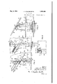
Figure 1 is a transverse sectional view of a drop bottom railway car illustrating my invention.
Fig. 2 is a sectional view taken on line 2 2, Fig. 1. I
Fig. 3 is a sectional view taken on line 33, Fig. 1.
Fig. 4 is a side elevational view of a portion of the car illustrated in Figure 1, apart of one of the side sheets being broken away.
Fig. 5 is a fragmentary perspective view of the inside of the car showing the arrangement of parts of the car construction adja cent one end of the body bolster.
Fig. 6 is a sectional view taken on line 66, Fig. 2.
Fig. 7 is a view partly in section and partly in elevation taken on line 77, Fig. 6.
Fig. 8 is a fragmentary front elevational view of the body bolster showing a portion of a side stake and the auxiliary floor sheet supporting member connected thereto.
Fig. 9 is a sectional view taken on line -9 9, Fig. 1.
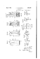
Fig. 10 is a plan view of one of the bolster sections.
Fig. 11 is a front elevational view of the bolster section illustrated in Fig. 10.
Fig. 12 is a bottom view of the same ster section.
Fig. 13 is an elevational view of the'inner end of the bolster section.
bol-
Fig. 14 is a sectional view taken on line 1414, Fig. 11. I
Fig. 15 is a sectional View taken on l ne 1515, Fig. 11.
Fig. 16 is an-elevational View of the outer end of the bolster section illustrated in Fig. 11.
Fig. 17 is a sectional view taken on the line 1717, Fig. 11.
' Fig. 18 is a fragmentary sectional. view.
taken on the line 18-18, Fig. 11.
Fig. 19 is a plan view of the auxiliary floor sheet supporting member.
Fig. 20 is an elevational view of the side of the auxiliary floor sheet supporting memher which is adapted to contact with one face of the side stake.
Fig."21 is an end elevational view of the same member.
Fig. 22 is a sectional view taken on line 2222, Fig. 20. I
Referring to the drawings, 1 indicates the car side sills and 2 indicates the box-like center sill, the latter being formed of a pair of flanged members 3 arranged in spaced relation and having their webs 4 substantially parallel. The members 3 have lower and upper flanges, the latter being connected by a plate 5. Interposed between the members 3 is a filler casting 6 which also serves to hold them together.
' The body bolster, generally designated by the reference numeral 7, is formed of a plurality of sections 8, preferably of cast steel.
Since the two bolster sections are of identical construction corresponding parts ofeach seca tension 11 overlying the top of the center sill..
These extensions may advantageously be rigidly connected by a plurality of. plate-like members 12 respectively disposed in overlapping relation to opposite sides of the extensions and secured thereto by rivets 13.
The sections of the bolster may be also con-- nected by a bottom cover plate 14 whichfin addition to being secured to the lower marginal flanges 15 of the bolster sections byrivets 16, passes beneath and is secured to the center sill and side sills. Each of the bolster sections may advantageously be formedadjacent their outer ends with an integral push pole pocket 63.
Adjacent the outer ends of the bolster, the lower marginal flange 15 thereof, is substantially horizontal to cooperate with the horizontally disposed legs 17 of the respective side sills. From the inner edges of these legs of the side sills portions 18, of the lower marginal flange 15 on the'opposite sides of the center sill, incline downwardly toward the latter and merge into intermediate horizontal portions 19 affording surfaces to which the usual side bearing wear plates may be attached. From this point portions 20 of the flange 15 incline downwardly toward the center sill and merge into the inner vertical flanges 9 of the bolster sections. Any suitable center bearingmay be employed for pivotally mounting the body bolster on the truck bolster, diagrammatically shown at 21, the upper part 22 of the center bearing being advantageously secured to the plate 14 and a portion of the center sill:
The upper portion of each bolster section is formed as an angle 23 having flanges 24 and 25, respectively, which are relatively inclined with respect to theweb portions 26 of the bolster, the flange 25 engaging with the under-side of the floor 27' of the car and serving as a support therefor. This angle portion 23 is so formed that its neutral axis lies substantially in the plane of the webs 26 of the floor contacting flange 25 of the bolster extensions 11 being offset downwardly so as to permit the top surface of the upper securing plate 12 to lie in substantially the same plane as the top surface of the flange 25' formed on the body portions of the bolster. Portions of the bolster either directly or indirectly thus supportingly engage the underside of the floor of the car for the entire width of the latter.
By this construction the forces imposed upon the upper portions of the bolsters by the weight of the lading which may be carried in the car directly above the bolster will act in the plane of the webs of the bolster sections, thus reducing to a minimum any eccentricity which may be developed in the floor supporting portion of the bolster by reason of these vertical forces.
Each of the bolster sections is provided with a plurality of diagonal truss-like flanges 28, projecting on opposite sides of the bolllt ster webs 26. The truss flanges of each of the holster sections extend from the outer lower corner thereof upwardly and inwardly to the top angle 23 of the bolster, thence downwardly and inwardly toward portion 19- of the bolster to which the usual side bearing wear plate is attached, then upwardly to the angle 23 of the bolster and from there downwardly to the upper corner of the center sill, thence merging into the inner vertical flange 9 of the bolster.
In this manner the truss flanges are arranged to most effectively resist forces tending to distort the bolster and particularly those forces applied to the bolster whenever the entire weight of the car is imposed on the side bearings. Furthermore, it will be appreciated, that since the portions of the truss flanges which respectively merge with and, in
fact, form continuations of the inner vertical flanges 9 of the bolster sections, diverge upwardly from adjacent the top of the centersill to the top of the sections, a greater area of the sections may be overlapped by and se cured to the connecting plates 12 than would be the case should the inner flanges be disposed in a vertical plane from top to bottom of the sections, whereby a most rigid connection between the sections is obtained.
At each end the bolster is fashioned to permit a side stake 29 to be rigidly secured to the web 26 thereof, the side stakes being advantageously formed as bulb angles. For this purpose a portion of the member 23 at the top of the bolster terminates at-a point 30 inwardly of the ends of the bolster and a portion of each of the outer vertical flanges 1O "terminates at a point 31. In this manner it will be seen that the outer face of the web 32 of the bulb angle contacts with a relatively large area of the web 26 of the bolster.
and may be rigidly secured thereto by a plurality of rivets 33; the outer leg 34 of the bulb angle, when the stake is thus attached to the bolster, constituting in effect a continuation of that portion of the outer Vertical flange 10 of the bolster which terminates at 31.
The side stakes are disposed in overlapping relation to the inner faces of the car sides 35 and project into the'car body. To prevent them from interfering with or interruptingthe flow of lading down the inclined floor 27 of the car and from retaining any lading within the car, each of the bolster sections is provided with a portion 36 projecting upwardly beyond the car floor in substantial alinement with the side stakes longitudinally of the car.
These projections are formed by a portion 37 of the web 'of the bolster, a portion 38 of the outer vertical flange 10 and a continuation of a portion of the floor contacting flange 25 which extends substantially vertically upward as at 39 and then inclines upwardly and outwardly as at 40, the portions 38 and 39 respectively constituting outer and inner surfaces or faces of the projections 36. In addition to being inclined transversely of the car and extending down wardly toward the longitudinal axis thereof, the upper surfaces 40 of the projections 36 are inclined downwardly longitudinally of v the car toward the center thereof to the same extent as the floor contacting flange 25.
The car sides 35 are preferably formed of a plurality of sheets 41 overlappingly sesecured to the leg 34 of the side stake by rivets 46 and to the outer vertical flange 10 of the bolster by rivets 47.
Instead of forming the marginal edges of the floor sheets 48 with inclined portions to overlie the top surfaces 40 of the projections 36 and securing the said floor sheet to the side sheets 49, adjacent the outer end of the bolster projections 36, it is preferred to form the side sheets 49 with inwardly inclined portions 50 which terminate in down-turned flanges 51. the latter being secured to the upstanding flange of the'floor sheet, by rivets 53. One of the rivets 53 on each side of the car rigidly secures the overlapping portions of the floor sheet 48 and the side sheets 49 to the corresponding inner faces 39 of the projections. The inclined portions 50 of the side sheets may advantageously be secured to the inclined top portions 40 of the bolster projections by rivets 54.
The upper corners of the floor sheet 55 are cut away to pass around the side stakes and the marginal edges of the floor sheet are flanged as at 56, the latter overlapping a portion of the inner face of each of the legs 34 of the side stakes and the inner face of the side sheets 45 which extend downwardly and are secured by any suitable means to the upstanding legs of the respective side sills. The marginal flanges 56 of the floor sheet 55 are secured to the cooperating portions of the side stakes and side sheets 45 by rivets 57. The portion of the floor sheet 55 adjacent each of the side stakes is supported on its underside by a bracket or auxiliary member 58 which is rigidly secured to the web of the neighboring side stakes by rivets 59.
The upper surface 60 of the member 58 is inclined correspondingly to the floor contacting flange 25 of the bolster and the face of the member contacting with the side stake is fashioned with a plurality of recesses 61 and 62 for respectively receiving the protruding portion of the side stake and one of the rivets employed for securing th side stake to the bolster. The rivets 59 which secure the member 58 to the side stake also serve as additional means for rigidly securing the latter to the bolster.
It will thus be appreciated that any lading in longitudinal alinement with the stake between the car end and the body bolster will be deflected transversely of the car toward the floor sheet 48 by the inclined portions 50 of the side sheets 49. The projections 36, in addition to affording a support for the in clines 50 of the side sheets, permit a greater number of rivets to be used in securing the side stake to the bolster than would be the case with. bolsters of usual design. Since a 'major part of the force required for supsteel. sections, each of said sections having an integral upstanding plate-like extension overlying the top of the center sill and each having an upwardly extending flange terminating adjacent the top of the extension, the lower portion of said flanges affording means for respectively securing the bolster sectlons to oppositesides of the center sill and the integral extensions of the bolster sections affording means for securing the sections together. I
2. In a railway car having a floor, a center sill, a body bolster formed of a plurality of sections respectively secured to opposite sides of the center sill, each of said sections being integrally formed with an upstanding platelike extension interposed between the top of the center sill and the car floor affording a support for the latter, and means rigidly connecting said bolster extensions.
3. In a railway hopper car having a slope sheet, a center sill, a body bolster formed'of a plurality of sections respectively secured to the opposite sides of the center sill, each of said sections being integrally formed with an extension interposed between the top of the center sill and the slope sheet, the top of each of the bolster sections and extensions being fashioned with an inclined flange affording a support for the slope sheet. and means rigidly connecting said bolster extensions. w
4. In a railway hopper car having an inclined floor sheet, a center sill, and a bodv bolster comprising two integrally formed sections respectively rigidly secured to opposite sides of the. center sill, each of said sections having a portion interposed between the floor sheet and top of the center sill and the upper surface of each section being formed to supportingly cooperate for substantially its entire length with the underside of the floor sheet.
In a railway hopper car having an. inclined floor sheet, a center sill, and a body bolster comprising two integrally formed sections respectively rigidly secured to opposite sides of the center sill, each of said sections the adjacent side sill and each being integral 1y formed with an upstandin extension overlying the top of the center sil and a plu- I ralityof plate-like members respectively disposed in overlapping relation to opposite sides of said extensions for rigidly connecting the bolster, sections.
7. In a railway hopper car having a slope sheet, the combination with a center sill and side sills, of a body bolster formed of a plurality of steel sections, said sections being respectively secured to opposite sides of the center sill and the adjacent'side sill and each of said sections being integrally formed with a portion projecting beyond the cooperating side of the center sill and overlying the top thereof, the top surface of each of said pro jecting portions being disposed in a plane substantially parallel with the plane of adj acent portions of the slope sheetfor cooperatlng therewith, and a plurality of plate-like members respectively overlapping opposite sides of said projecting portions for rigidly connecting said bolster sections.
8;In a railway car having a floor, the combination with a center sill and side sills, of abody bolster disposed below the car floor and formed of a plurality of sections respectively secured to opposite sides of thecenter sill and the adjacent side s ll, each of said bolster sections having portions projecting upwardly beyond the car floor and arranged in overlapping engagement with portions of the car sides, and means for rigidly connecting said bolster sections-above the center sill.
9. In a railway car having a floor sheet and a side sheet, a bodybolster disposed below the floor sheet and integrally formed with an inclined top flange for supporting cooperation therewith. a portion of said flange adjacent one end of the bolster being inclined transversely of the car, the floor sheet'and side sheet being secured together and one of said sheets being provided with a portion overlying the transversely inclined portion of the top flange.
10. In a ra lway car having a floor sheet and a side sheet. a body bolster disposed below the floor sheet and integrally formed w th a top flange for supporting co-operation therewith, a portion of the bolster adjacent one of its ends projecting upwardly above adjacent portions of the floor sheet, said portion being providedwith-a top flange inclined transversely of the car and extending downwardly toward the longitudinal axis thereof, said last named flange being integrally united to and constituting a continuation of the top flange of the bolster, the floor sheet and side sheet being secured together 7 and one of said sheets being fashioned with 1 sheets, and a body bolsterdisposed below the floor and integrally formed with an inclined top flange for supporting co-operation therewith, portions of the bolster adjacent its opposite ends projecting upwardly above adjacent portions of the car floor. said projecting portions being respect vely formed with top flanges inclined transversely of the car, said last named flanges being integrally united to and constituting continuations of the top flange of the bolster, the side sheets being bent inwardly to overlie the top flanges of said upwardly projecting portions of the bolster. 3.;
12. In a ra lway car having a floor, side sheets, and a bolster disposed below the floor and integrally formed with an inclined top flange for supporting co-operation therewith, portions of the bolster adjacent its onposite ends projecting upwardly beyond adjoining portions of the said floor. said projecting portions being respectively formed w th top flanges inclined transversely of the car and extending downwardly toward the longitudinal axis thereof, said last named flanges being integrally united to and constituting continuations of the top flange of the bolster, the lower marginal edges of the side sheets adjacent the bolster being flanged inwardly and downwardlv to respectively overlappingly engage the flanges of said projections.
13. In a ra lway car havinga floor sheet and side sheets, abody bolster disposed beextending downwardly toward the longilow said floor sheet and integrally formed with an inclined top flange for supporting co-oneration therewith. said bolster having portions adjacent its opposite ends projecting upwardlv above the adjacent portions of said floor sheet. said upwardly projecting portions be ng respectively formed with top flanges inclined transversely of the car and tudinal axis thereof..said last named. top flanges being integrally united with and constituting continuations of the top flange of the bolster, the lower marginal portions of the side sheets adjacent the o posite ends of the. bolster being respectively flanged inwardly to overl e the inclined flanges of said projecting portions and the lateral marginal edges of the floor sheet being flanged upwardly and respectively secured to the marginal edges of side sheets.
14. In' a railway car having a plurality of side sheets, abolster integrally formed with an upstanding projection adjacent one of its ends, said projection being formed with inner and outer flanges, said sheets being overlappingly secured to each other adjacent the bolster and one of said sheets being secured to the outer flange of said projection and the other of said sheets being secured to the inner flange of said projection.
15. In a drop bottom railway car, a car body having a side sheet and a floor sheet, a side stake projecting inwardly beyond the side sheet, and a body bolster disposed below the floor sheet and integrally formed with a top flange for supporting co-operation therewith, said side stake being rigidly secured to the bolster, the portion of the top flange of the bolster adjacent the side stake being inclined transversely of the car and extending downwardly toward the longitudinal axis thereof and one of said sheets being fashioned with a portion to overlappingly engage the said transversely inclined portion of the top flange of the bolster.
16. In a railway hopper car having a slope sheet, a body bolster disposed below said slope sheet and integrally formed with an inclined top flange for supporting cooperation therewith, said bolster having adjacent one of its ends a portion projecting upwardly above adjacent portions of the slope sheet, said portion being provided with a top flange inclined transversely of the car, said last named flange being integrally united to and consti tuting a continuation of the top flange of the bolster, a plurality of side sheets overlappingly secured together adjacent the said end of the bolster, and a side stake secured to said bolster adjacent the projecting portion thereof, one of said sheets being secured to said stake in overlapping relation to the outer face thereof and the other of said sheets being flanged inwardly to overlie the inclined flange of the projecting portion of the bolster,
the said flanged portion terminating adjacent the inner edge. of said stake and being secured to the slope sheet.
17. In a railway hopper car having a'slope sheet, a body bolster disposed below said slope sheet and integrally formed with an end. I
sheets overlappingly secured together adjacent an end of the bolster, and-a car stake secured to said bolster adjacent the projecting portion thereof, one of said side sheets being secured to the outer face of said stal ze and end flange of the bolster and theother of said side" sheets being flanged inwardly I and .downwardly to overlie the top flange of said bolster projecting portion, the flanged portion of'said side sheet terminating ad-- 7 jacent the inner edge of said car stake and being secured to the lateral marginal edge stituting a continuation of the flange of the bolster and being integrally unit-ed thereto, by a substantially vertical flange, a plurality of side sheets, and a car side stake secured to said bolster. adjacent its upwardly projecting portion and inwardly of the side sheets, one of said slope sheets being secured to an adjoining side sheet adjacent the outer edge of the said stake and the other of said slope sheets being secured to an adjoining side sheet adjacent an inner edge of the stake.
19. In a railway hopper car having a plurality of slope sheets, a body bolster having an inclined topsurface for cooperative association with the undersides of said slope sheets, said bolster being fashioned adjacent one of its ends with an upstanding projection, a plurality of side sheets, a car side stake secured tothe bolster adjacent its upstanding projection, one of said slope sheets being secured to an adjoining side sheet adjacent the outer edge of the car stake and one of said slope sheets being secured to an adjoining side sheet adjacent the inner edge of the stake, and means rigidly secured to the car stakefor supporting a portion of the slope sheet terminating adjacent the outer edge of the stake.
A body bolster for railway hopper cars having a web and a top flange, the upper surface of said flange being inclined for supporting cooperation with the car floor, said flange projecting on'opposite sides of the said 21. A body bolster for railway hopper cars having a web and a top flange projecting on opposite sides of the latter, the portions: of the flange on one side of the web terminating short of the ends of the bolster whereby car side stakes may be secured to said web.
122. A body bolster for railway hoppercars having a web and an inclined top flange, said flange projecting on opposite sides of the web, portion's'of the flange on one side of the web adjacent the respective ends of the bolster being cut away to provide recesses-for receiving car side stakes.
' In a railway car having a body bolster jecting on opposite sides of the latter, and
car side, stakes respectively secured to the said web of the bolster adjacent its opposite ends.
24. In a'railway car, the combination with an inclined floor, ofa body bolster having a web and a top flange, the latter projecting on opposite sides of the web and being in supporting cooperation with the inclined floor, the web and flange of the bolster being connectedby a portion forming an angle with the web.
25. In a railway car, the combination with an inclined floor, of a body bolster having a web and a top flange, the latter projecting on opposite sides of the web and being in supporting cooperation with the inclined floor, said web and flange of the bolster being integrally united by a portion substantially normal to the inclined floor.
26. In a railway car, the combination with an inclined Hood, of a body bolster having a web and a top flange, the latter projecting on opposite sides of the web and being in supporting cooperation with the inclined floor, said web and flange being integrally united by a portion forming an oblique angle with the web and a substantially right angle with the flange.
27. In a railway car, the combination with an inclined floor, of a body bolster having a web and a top flange, the latter projecting on opposite sides of the web and being in supporting cooperation with the inclined floor, portions of the flange on one side of said web terminating short of the ends of the bolster whereby car side stakes may be secured to said web, the top flan e and web being connected by a portion orming an oblique angle with the web.
28. In a railway car, the combination with an inclined floor, of'a body bolster having a web portion and an inclined top flange, the latter projecting on opposite sides of the web' and being in supporting cooperation with the car floor, the lower marginal edge of said flange being integrally connected to the web portion of the bolster by a portion extending at an oblique angle to the latter.
29. In a railway car, the combination with an inclined floor, of a body bolster having a web portion and an. inclined top flange,
the latter projecting on opposite sides of the projecting portion being provided with a top flange inclined downwardly and transversely of the car, said last named flange being integrally united to the end flange and inclined 5 top flange of the bolster and constituting a continuation of the latter.
31. In a railway car the combination with an inclined floor, of a body bolster having a web, the upper portion of said bolster being of substantially angle shape. the legs of said angle respectively disposed in planes forming oblique angles with the web and one of said legs being in supporting cooperation with the inclined floor. V
32. In a railway car, the combination with an inclined floor, of a body bolster having a web and an angle-shaped upper portion, one leg of said angle being adapted to supportingly cooperate with the inclined floor and the neutral axis of said angle portion being disposed substantially in the plane of the web of the bolster.
33. In a railway car, the combination with an inclined floor, of a body bolster having a web portion and provided with an end flange and with an inclined top flange, the latter projecting on opposite sides of the web of the bolster and being in supporting cooperation with the car floor, said web adjacent an end of the bolster projecting upwardly above adjacent portions of the car floor, said upwardly projecting portionbeing fashioned with a flange inclined transversely of the car and integrally united to said end flange and inclined topflange of the bolster and constituting a continuation of the latter, and a car side stake rigidly secured to the upwardly projecting web portion of the bolster.
34. In a railway car having an inclined floor, the combination with a center sill, of a body bolster formed of a plurality of sections respectively secured to opposite sides of the center sill, each of said sections having a web and an inclinedtop flange, the latter project ing on opposite sides of the web and being integrally united theretoby a portion forming an oblique angle therewith, each of said sections being integrally formed with an upstanding plate-like extension interposed befloor, said extensions being also respectively formed with inclined top flanges and a portion extending at an oblique anglevto the web of the bolster, and means rigidly connecting said bolster extensions.
35. In a.,ra'ilway car having an inclined floor, the, combination with a center sill, of a. body bolster formed of a plurality of sections, each of said sections being provided with a flange adjacent its inner end, the lower portions of said flanges being respectively securedto opposite sides of the car center sill and the upper portions of saidflanges diverging upwardly from adjacent the top of the center sill to adjacent the top of the bolster,
tween the top of the center sill and the car said bolster sections being integrally formed with upstanding plate-like portions interposed between the top of the center sill and car floor affording means for rigidly connecting the sections. v
36. In a railway car having an inclined floor, the combination with a center sill, of a body bolster formed ofa plurality of sections respectively secured to opposite sides of the center sill, said bolster sections being provided with reinforcing flanges which diverge upwardly from adjacent the top of the center sill to adjacent the top of the bolster and being further provided with portions interposed between the top of the center sill and car floor affording means for rigidly connectin the sections.
37. In a railway car having an inclined floor, the combination wit-h a center sill, of a body bolster formed of a plurality of sections respectively disposed on opposite sides of the center sill, each of said sections being integrally formed with a plate-like extension interposed between the top of the center sill and the car floor, said sections being respectively formed with substantially vertical flanges for attachment to opposite sides of the car center sill and with reinforcing flanges which diverge upwardly from adjacent the lower edges of the extensions to adjacent the upper edges thereof.
88. In a railway car having an inclined .floor, the combination with a centersill, of
a body bolster formed of a plurality of sections respectively disposed on opposite sides of the center sill, each of said sections being provided with a web and an inclined top flange, a portion of the web of each section being interposed between the top of the bolster and the car floor, each of said sections being provided with a flange projecting on opposite sides of the web thereof, the lower portions of the respective flanges being adapted to be rigidly secured to opposite sides of the car center sill and the upper portions of said flanges diverging upwardly from adjacent the lower edges of the portions of the web interposed between the center sill and car floor to adjacent the top of the bolster, and a plurality of plate-like members overlapping opposite sides of the portions of the webs of the sections interposed between the top of the Center sill and car floor.
39. In a railway car having an inclined floor, the combination with a center sill, of a body-bolster formed of a plurality of sections respectively disposed on opposite sides of the center sill, each of said sections being provided with a portion interposed between. the top of the center sill and the inclined floor,
each of said extensions having a substantially vertically disposed pbrtion and atop flange, and a plurality of members respectively having portions overlapping opposite sides of the vertically disposed portions and top flanges floor,the combination with a center sill, of a I body bolster formed of a plurality of sections respectively disposed on opposite sides of the center sill, each of said sections being pro-v vided with an extension interposed between the top of the center silland the floor, each of said extensions having 'a substantially vertically disposed portion, a top flange and an intermediate inclined portion, and a plurality of members respectively having portions overlapping opposite sides ofthe vertically disposed portions, the top flanges, and the inclined portions of the said extensions for connecting the bolster sections.
r 41. In a railway car having an inclined floor, a center sill, a body bolster formed of a plurality of sections respectively disposed on opposite sides of the center sill, each of said sections being integrally formed with an extension interposed between the center sill and car, floor, said extensions being disposed in spaced relation to the center sill and affording a support for adjacent portions of the floor, and rigid means secured to said extensions for connecting said sections.
42. In a railway car having an inclined floor, a center sill, a body bolster formed of a plurality of'sections respectively disposed on opposite sides of the center sill, each of said/sections being integrally formed with an extension interposed between. the center sill and car floor, the top of each section and its extension being provided with a flange for supportingly cooperating with the car floor, and a plate-like member rigidly secured to said extensions for connecting said sections, said member having aportion-inter of the extenposed between the top flanges sions and the car 'floor.
43. In a railway car having an inclined floor, a center sill, a body bolster formed of a plurality of sections respectively disposed on opposite sides of the center sill, each of said sections being integrally formed with an extension interposed between the center sill and car floor, the upper portion of each extension being formed with a flange disposed in a plane substantially parallel with the floor for supportingly cooperating with ad-' jacent portions of the latter and a platelike'member having a portion disposed in overlapping relation to the said flanges of the extensions and rigidly secured to the i 4 latter for connecting said sections.
44. In a railway car having aninclined floor, a center-sill, a body bolster formed of a plurality of sections respectively disposed on opposite sides of the center sill, each of said sections having-truss-like flanges diverging downwardly from the upper portion thereof at aa point laterally of the center sill, each of said sections being also providport for adjoining portions of the latter,
and means'rigidly connecting said sections involving a plate-like member secured to said extenslons.
45.- In a railway car having .an inclined.
floor, a center sill,'a body bolster formed of a plurality of sections respectively disposed on opposite sides of the center sill,
each of said sections being integrally provided with truss-like flanges diverging downwardly from the top portion thereof, one of said flanges extending toward the center sill and the other extending toward that portion of the section which is adapted to cooperate with a side bearing, each section being also integrally provided with an extension interposed between the top of the center sill and the inclined floor, said extensions being disposed in spaced relation to the center sill and affording a support for adjacent portions of the car floor, and means secured to said extensions for rigidly connecting said sections.
In testimony whereof we afl'ix our signatures.
JOHN A. PILCHER. WILLIAM E. WINE.
Priority Applications (1)
| Application Number | Priority Date | Filing Date | Title |
|---|---|---|---|
| US264466A US1856400A (en) | 1928-03-24 | 1928-03-24 | Railway car |
Applications Claiming Priority (1)
| Application Number | Priority Date | Filing Date | Title |
|---|---|---|---|
| US264466A US1856400A (en) | 1928-03-24 | 1928-03-24 | Railway car |
Publications (1)
| Publication Number | Publication Date |
|---|---|
| US1856400A true US1856400A (en) | 1932-05-03 |
Family
ID=23006182
Family Applications (1)
| Application Number | Title | Priority Date | Filing Date |
|---|---|---|---|
| US264466A Expired - Lifetime US1856400A (en) | 1928-03-24 | 1928-03-24 | Railway car |
Country Status (1)
| Country | Link |
|---|---|
| US (1) | US1856400A (en) |
-
1928
- 1928-03-24 US US264466A patent/US1856400A/en not_active Expired - Lifetime
Similar Documents
| Publication | Publication Date | Title |
|---|---|---|
| US1856400A (en) | Railway car | |
| US1962717A (en) | Freight car | |
| US861208A (en) | Car-body. | |
| US2012999A (en) | Body bolster | |
| US2160450A (en) | Railway car | |
| US736739A (en) | Underframing for railway-cars. | |
| US750049A (en) | Metallic-gar construction | |
| US2015188A (en) | Car underframe | |
| US743497A (en) | Gondola car. | |
| US1944421A (en) | Railway car | |
| US1068529A (en) | Car-truck. | |
| US831652A (en) | Bolster construction for cars. | |
| US1636534A (en) | Ore car | |
| US772572A (en) | Railway-car. | |
| US734324A (en) | Body-bolster for railway-cars. | |
| US728582A (en) | Railway-car truck. | |
| US953176A (en) | Railway-car. | |
| US685452A (en) | High-side gondola car. | |
| US784261A (en) | Metallic car-underframe. | |
| US1851995A (en) | Railway car | |
| US2085621A (en) | Mine car | |
| US688019A (en) | Hopper-bottom car. | |
| US691637A (en) | Low-side gondola car. | |
| US1037576A (en) | Center-bearing for railway-cars. | |
| USRE12340E (en) | Low-side gondola car |