US1851995A - Railway car - Google Patents
Railway car Download PDFInfo
- Publication number
- US1851995A US1851995A US355847A US35584729A US1851995A US 1851995 A US1851995 A US 1851995A US 355847 A US355847 A US 355847A US 35584729 A US35584729 A US 35584729A US 1851995 A US1851995 A US 1851995A
- Authority
- US
- United States
- Prior art keywords
- bolster
- car
- members
- center sill
- bottom plate
- Prior art date
- Legal status (The legal status is an assumption and is not a legal conclusion. Google has not performed a legal analysis and makes no representation as to the accuracy of the status listed.)
- Expired - Lifetime
Links
- 238000010276 construction Methods 0.000 description 5
- 238000005452 bending Methods 0.000 description 4
- 238000005266 casting Methods 0.000 description 3
- 239000011324 bead Substances 0.000 description 2
- 230000000694 effects Effects 0.000 description 2
- 230000015572 biosynthetic process Effects 0.000 description 1
- 229940000425 combination drug Drugs 0.000 description 1
- 239000000945 filler Substances 0.000 description 1
- 230000004048 modification Effects 0.000 description 1
- 238000012986 modification Methods 0.000 description 1
- 230000007935 neutral effect Effects 0.000 description 1
- 230000003014 reinforcing effect Effects 0.000 description 1
- 230000000284 resting effect Effects 0.000 description 1
Images

Classifications
-
- B—PERFORMING OPERATIONS; TRANSPORTING
- B61—RAILWAYS
- B61F—RAIL VEHICLE SUSPENSIONS, e.g. UNDERFRAMES, BOGIES OR ARRANGEMENTS OF WHEEL AXLES; RAIL VEHICLES FOR USE ON TRACKS OF DIFFERENT WIDTH; PREVENTING DERAILING OF RAIL VEHICLES; WHEEL GUARDS, OBSTRUCTION REMOVERS OR THE LIKE FOR RAIL VEHICLES
- B61F1/00—Underframes
- B61F1/08—Details
- B61F1/12—Cross bearers
Definitions
- My invention relates to railway cars and more particularly to improvements in body bolsters. s
- a principal object of the invention is to provide a body bolster of simple and rugged construction especially suitable for hopper cars. Another object of the invention is to provide improved means for rigidly connecting the bolster to associated parts of the car structure.
- a principal feature of the invention consists in constructing the body bolster with top and bottom plate members, the top mem-v ber affording a support for the car floor and the bottom plate member having a portion for attachment to the top of the car center sill.
- Another feature of the invention resides in providing a body bolster having a bottom plate member adapted to be secured to the top of the car center sill with a plur'ality of depending portions afiording means to which side bearing wear plates may be respectively secured.
- a further feature of the invention consists in constructing a railway car with a body bolster adapted to rest upon and be secured to the top of the car center sill, the bolster being provided with depending portions af fording means to which side bearing wear plates may be respectively secured, and in associating therewith a plate passing beneath the center sill and secured thereto and to the depending portions of the bolster for rigidly connecting it to the center sill.
- a still further feature of the invention resides in constructing a body bolster with end walls provided with substantially vertical recesses for respectively receiving car side stakes.
- car center sill with a plurality of pairs of depending members, one pair of said members affording means to which side bearing wear plates may be attached and the other pair of said members aflording means to which car side sills may be respectively attached.
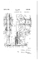
- Figure 1 is a fragmentary transverse sectional View of a railway car, the body bolster being in elevation;
- Figure 2 is a fragmentary plan view of that portion of the car construction illustrated in Figure 1.
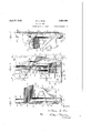
- Figure 3 is a fragmentary sectional view taken on line 33of Figure 1.
- I v Figure 4 is a framnentary sectional view taken on line 44 of Fig. 3.
- Figure 5 is a fragmentary sectional view taken on line 55 of Fig. 3.
- Figure 6 is a side elevational view of the body bolster showing its relation to the various elements of the car frame.
- Figure 7 is a fra mentary sectional view taken on line 77 0 Figure 1.
- Figure 8 is a fragmentary viewtaken on line 8-8 of Figure 1.
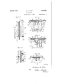
- Figure 9 is an end elevational view of the body bolster.
- Figure 10 is an enlarged top view, partly in section and partly in elevation showing the connection between the body bolster and one of the car side stakes.
- FIG. 11 is a detail fragmentary view taken on line 11-11 of Figure 3.
- Figure 12 is a fragmentary sectional View taken on line 1212 of Figure 1, the bottom connectingplate and side bearing wear plate being omitted.
- Figure 13 is a view similar to Figure 10 showing amodified form of the invention.
- 1 indicates the box-like center sill having two sill members 2, each being provided with a web 3 and top and bottom flanges 4;
- the sill members may rigidly connected thereto by rivets 10 is the usual center casting or filler member 11.
- the bolster 12 which may advantageously be formed as a unitary casting and which is adapted to be interposed between the car floor and car center sill, is provided with an inclined top plate member 13 and a substantially horizontal bottom plate member 14.
- the top plate member 13 is arranged to lie in a plane parallel with the inclined floor sheets 15, the latter being supported thereby and overlappingly secured thereto by rivets 16.
- the bottom plate member 14 extends substantially continuously from one end of the bolster to the other and the central portion thereof rests upon and is rigidly secured to the top of the center sill.
- the rivets '7 employed for connecting the top cover plate 6 of the center sill to the sill members thereof may be employed for securing the bottom plate member 14 of the bolster to the center sill and the portion of the bottom plate member engaging the center sill is preferably enlarged as at 17 so that a large number of rivets may be employed for obtaining a very rigid connection between the bolster and center sill.
- members 18, respectively affording means to which side bearing wear plates 19, of any usual construction, may be secured.
- These depending members are rigidly connected to the center sill by means of the bottom cover plate 8 and rivets 20, the latter also serving as connecting means for the side bearing wear plates 19.
- the top and bottom plate members of the bolster are preferably connected by a substantially continuous system of transverse webs.
- the corresponding webs in each half are designated by similar reference numeralsf
- Adjacent the center of the bolster the top and bottom plate members are connected by two substantially vertical webs 21 which are respectively preferably arranged substantially in the same planes as the webs 3 of the sill members 2.
- top and bottom plate members are also connected by transverse substantially vertical webs 22, respectively disposed in planes intersecting the surfaces of the downwardly depending members to which the side bearing wear plates are secured.
- the adjoining vertical webs 21 and 22 are each connected by transverse diagonal webs 23which respectively extend upwardly from the point of intersection of the webs 21 bolster therein. To efl'ectually resist these bending I they intersect substantially half way between the vertical webs 22 and the ends of the bolster.
- the top and bottom plate members are connected by end walls 25, which -will be hereinafter described in detail. Due
- the side plates 4 26 diverge slightly downwardly and in order to reduce the weight of the bolster with-v out affecting its strength, they may be suitably apertured as at 27.
- Each of-the apertures is preferably of a shape similar to that formed ,by adjacent portions of the top and bottom plate members and the neighboring transverse webs.
- the portions of the side plates bounding the openings may, if desired, be formed with rigidifying beads or ribs 28.
- the central portion of the body bolster is in effect a trussed girder having upper and lower chords connected by diagonal and substantially vertical truss members, the upper and lower chords and the outer vertical members being of substantially channel section and the diagonal and inner vertical members being substantially I-section.
- This 7 web may be formed with apertures31 similar to'thoseformed in the side plates 26. From the foregoing it will be observed that adjacent its end portions, where bending moments are a minimum, the bolster is of substantially I-section while adjacent its cen-' tral portion, where bending moments are greatest, the bolster is of substantially box section. In order that the neutral axis of the top plate member adjoining the longitudinal webs 30 may lie substantially in the plane of the latter, the upper portion of the webs incline'upwardly,-as at 32, in a direction opposite to that of the top plate member, intersecting it at substantially right angles.
- each of the depending members 18 is formed with a web 34 and a bottom plate 35, the latter affording the means heretofore described towhich the side bearin wear plates 19 are secured.
- each is provided with a pluralityof flanges36 and 37, the flanges 36 being arran ed in spaced relation and pro jecting inwar 1y, from the. web 24 toward thecenter sill and the flange 37 being disposed in a plane intermediate the planes of the flanges 36 and projecting outwardly from the web toward the adjacent side sill. All of the flangesmay be suitably reinforced by marginal ribs or beads 38.
- the flanges 36 are preferably disposed in the plane of the V neighboring side plates 26 and, in effect, constitute continuati'ons thereof, while the flanges 37 are disposed in the longitudlnalwebs 30 and likewise constitute prolongations thereof;
- the webs 34 thereof project on opposite sides of the flanges '36 and they taper upwardly so that their upper portions will be of a width corresponding to that-of'the bot- 1 tom plate member 14.
- the respective outer ends of the longitudinal webs 30 are bifurcated to form substantially vertical recesses 39 in the end walls 25 of the bolster to receive suitably shaped car side stakes.
- the recesses formed in the ends of the bolster are substantially V-shaped and receive correspondingly shapedside stakes 40.
- the side stakes are formed with laterally projecting flanges rigidly secured in overlapping relation tothe outer face of the end walls 25 by rivets 41. In order that a very rigid connection may be obtained between thebolster and'side stakes, the latter extend downwardly to apoint adjacent the bottom plate member 14. It will, of course, be appreciated thatmany forms of side stakes may be employed which may or may not necessitate a modification in the end formation of the bolster.
- a side stake 42of T-section is illustrated, the T being arranged so that its stem'43 projects into the recess formed :inthe end of the bolster andso that-its flange 44 may be ov erlappingly secured to the outer face of the end wall of the bolster.
- IVhile the major'portion of the outer face of eachof therecesses'in the ends of the bolster are smooth andsubstantially continuous, the portion45 thereof adjacent the intersection of the top plate member and the inclined portion 32'of-the web is cut away to obviate the necessity ,of using cores at this point in the casting operation of the bolster.
- the side stakes extend continuously from adjacent the bottom of the ⁇ bolster to the top of the car, the latter portion of the car construction is not disclosed as it forms no part of the invention.
- the side sheets 4620f the car are overlappingly secured to the outer faces of the flan es .of the side'stakes by the rivets 4'1, emp oyed for connecting the sidestakes to the bolster, and by the rivets 47.
- the adjoining ends of the side sheets may be connected'by a plate 48 which also "functions to close the recess formed in theouter faces of theside stakes illustrated in the preferred embodiment of theinvention."
- the marginal side plane of the wedges of the floor-sheets 15 may beflanged upwardly, as'at 49, and secured to'neighboring portions of the side sheets by any suitable one end of the cal to the other,.it is preferred to make them in sections, and 51, respectively.
- the sill 50 -which extends continuously from the bolster to the adjacent end of the car, is of greater depth than the sill 51, which extends from one body bolster of the ear to the other.
- Each is formed with a web52 and a bottom flange 53, which are respectively connected in overlapping relation byrivets 41 and 5-1 to the end walls of the bolster and the inturned bottom thereof.
- a body bolster for railway cars adapted to be interposed between'the car floor and the car center sill, said bolster being integrally formed with an inclined top plate member and a substantially horizontal bottom plate member, the latter affording means for rigidly securing the bolsterto the top of the center sill, said top and bottom plate members b'eing connected adjacent their central portions by side plate members and adjacent their ends by longitudinally extending substantially centrallydisposed webs.
- a body bolster for railway cars adapted to be interposed between the car floor and car center sill, said bolster being of substantially box-like section adjacent its central I flange 55 portion and of substantially I-section adjacent its end portions and having top and bot tom plate member'sextending substantially continuously from one end of the bolster to thepther, said top plate-member being inclined and adapted to serve as a support for the car floor and the said bottom member being substantially horizontal and adapted, to
- a center sill and side sills of a body bolster rigidly secured to the side sills and interposed between the floor of the car and the center Isill, said bolster having a'bottom plate member extending substantially continuously from one end thereof to the other above the center sill and secured to the latter, said bolster being provided with depending portions disposed intermediate the center sill and side sills aflording means to which side bearing -wearplates may be respectively secured.
- a bod-y bolster for railway cars adaptedto be 'interposed'between the car floor and car center 'sill,said bolster involving a top plate member, a horizontal bottom plate member extending. substantially continuously from one end of the .bolster to-the other, the central portion of said bottom plate member being adapted to be secured to the top of the car center sill, and depending members formed.
- a railway car having a center sill comprising spaced beams respectively provided with substantially vertical .webs and upper and lower flanges, a top cover plate connecting the'upper flanges of said beams and a body bolster adapted to be interposed between the car floor and car center sill, said bolster involving top and bottom plate members adapted to be respectively secured to thecar floor and top cover plate of the center sill, a plurality of substantially vertical transversely extending webs connecting said plate members adjacent the point of attachment of the bolster to the center sill, said webs being respectively disposed in the planes of the webs of the center sill beams an d substantially vertical transversely'extending webs respectively connecting said members adjacent the point to .wh1ch side bearing wear plates are adapted to be respectively secured to the bolster.
- a bodybolster for ed to be interposed between the car floor and car center sill, said bolster involving top and bottom plate members, adapted to' respectively cooperate with the car floor and center sill, said top and bottom plate-members adjacent their central portions beingconnected b y a plurality of substantially vertical transversely extending webs and being also connected intermediate the ends of the bolster and the adjacentcentral webs bysimilarlv formed webs, the adjacent intermediate and central webs being connected by diagonal webs respectively extending upwardlyfrom the point of intersection of the central webs and bottom plate member to the point' of intersection of the intermediate webs and top plate member.
- a body bolster involving an inclined top plate member and a bottom plate member respectively secured to the car floorand center sill, side plate members respectively connecting the marginal edges of the portions of the top and bottom plate members adjacent thecenter I sill, transverse webs connecting said side plate members, and webs extending longitudinally of the bolster respectively connecting the portions of the top and bottom plate members adjacent the side sills, the portion of each of the longitudinal webs adjacent the top plate member being inclined in a direction opposite to that of the latter, the said transverse webs respectively adjacent the inclined portion of the longitudinal webbeing connected by an railway cars adapt- -"nclined portion disposed in a planesubstantially parallel to the top plate member.
- a body bolster for railway cars having top and bottom plate members and end walls depending below said bottom plate member, said end walls being flanged inwardly to 'afl'ord means to which side sills may be respectively secured.
- An integral body bolster for a railway car having top and bottom plate members integrally connected at their opposite ends by substantially vertical end walls, eachof said end walls and the adjacent portions of the top and bottom plate members being provided with a vertically extendingrecessed portion for receiving a car side stake.
- An integral body bolster for railway cars adapted to extend continuously from one side of the car to the other above the car center sill, said bolster being of substantially box-like section adjacent its central portion and of substantially I-section adjacent its end portions. 7
- a body bolster for railway cars having top and bottom plate members, and side plate members connecting said top and bottom plate members'adjacent the central portion of the'bolster, the central portion of thelower plat-e member projecting outwardly beyond said side plate members and adapted to be rigidly secured to the cent-er sill.
- a body bolster for railway cars having top and bottom plate members, side plate members connecting said-top and bottom a plate members adjacent the central portion from one side thereof and a single flange projecting from the other side thereof, said last named flange being disposed in a plane intermediate the planes of said spaced flanges.
- a body bolster for railway cars involving top and bottom'chord members and truss members integrally connecting said chord members, said truss members respectively extending upwardly from said lower chord member at points in substantially vertical alinement with portions of the bolster coopv erable with truck side bearings, and each of said-truss members includedin a web, a flange i projecting from one side'o the web intermediate its marginal-edges, and spaced flanges projecting from the other side of the Web adjacent its marginal edges.
- a body bolster for railway cars involving top and bottom chord members and truss members integrally connecting said chord members, said truss members respectively extending tipwardlyfrom said lower "chord member at points in substantially vertical alinement with portions of the bolster coop-. erable with truck side bearings, and each of said truss members including a web provided with a flange pro ectlng from one side thereof and a plurality of spaced flanges projecting from the other, side thereof, each of said spaced flanges being provided wardly projecting rib.
- the combination wit a center sill and side sills, of a body bolster rigidly secured to said side sills and having a substantially. horizontally disposed bottom plate member resting upon and secured-to the center sill, members depending from said bot-' with an inalinement With portions of the bolster c'o0p erable with truck side bearings, and each 011 sa d truss members including a web provided with horlzontally spaced flanges projecting
Landscapes
- Engineering & Computer Science (AREA)
- Mechanical Engineering (AREA)
- Body Structure For Vehicles (AREA)
Description
W. E. WINE RAILWAY CAR April 5, 1932.
Filed April 17, 1929 4 Sheets-Sheet glwuewto o April 5, 1932. w. E. WINE 1,851,995
' RAILWAY CAR Filed April 1'7, 1929 4 Sheets-Sheet 2 Ill April 5, 1932. w. E. WINE RAILWAY CAR Filed April 1'7, 1929 '4 sheet-sheet s W. E. WINE RAILWAY CAR April 5, 1932.
Filed April 17. 1929 4 SheetsSheet 4 gnmnfoz Patented Apr. 5, 1932 WILLIAM E. WINE,-
or TOLEDO, oHIo RAILWAY CAR Application filed April 17,
My invention relates to railway cars and more particularly to improvements in body bolsters. s
A principal object of the invention is to provide a body bolster of simple and rugged construction especially suitable for hopper cars. Another object of the invention is to provide improved means for rigidly connecting the bolster to associated parts of the car structure.
A principal feature of the invention consists in constructing the body bolster with top and bottom plate members, the top mem-v ber affording a support for the car floor and the bottom plate member having a portion for attachment to the top of the car center sill.
Another feature of the invention resides in providing a body bolster having a bottom plate member adapted to be secured to the top of the car center sill with a plur'ality of depending portions afiording means to which side bearing wear plates may be respectively secured.
A further feature of the invention consists in constructing a railway car with a body bolster adapted to rest upon and be secured to the top of the car center sill, the bolster being provided with depending portions af fording means to which side bearing wear plates may be respectively secured, and in associating therewith a plate passing beneath the center sill and secured thereto and to the depending portions of the bolster for rigidly connecting it to the center sill.
A still further feature of the invention resides in constructing a body bolster with end walls provided with substantially vertical recesses for respectively receiving car side stakes.
car center sill with a plurality of pairs of depending members, one pair of said members affording means to which side bearing wear plates may be attached and the other pair of said members aflording means to which car side sills may be respectively attached.
1929. Serial No. 355,847.
Other and more specific features of the invention residing in advantageous combina tions, relations and forms of parts will hereinafter appear and be pointed out in. the claims.
In the drawings illustrating preferred embodiments of the invention, I I .Figure 1 is a fragmentary transverse sectional View of a railway car, the body bolster being in elevation;
Figure 2 is a fragmentary plan view of that portion of the car construction illustrated in Figure 1.
Figure 3 is a fragmentary sectional view taken on line 33of Figure 1. I v Figure 4 is a framnentary sectional view taken on line 44 of Fig. 3.
Figure 5 is a fragmentary sectional view taken on line 55 of Fig. 3.
Figure 6 is a side elevational view of the body bolster showing its relation to the various elements of the car frame.
Figure 7 is a fra mentary sectional view taken on line 77 0 Figure 1.
Figure 8 is a fragmentary viewtaken on line 8-8 of Figure 1.
Figure 9 is an end elevational view of the body bolster.
Figure 10 is an enlarged top view, partly in section and partly in elevation showing the connection between the body bolster and one of the car side stakes.
Figure 11 is a detail fragmentary view taken on line 11-11 of Figure 3.
Figure 12 is a fragmentary sectional View taken on line 1212 of Figure 1, the bottom connectingplate and side bearing wear plate being omitted. v
Figure 13 is a view similar to Figure 10 showing amodified form of the invention.
Referring more particularly to the drawings, 1 indicates the box-like center sill having two sill members 2, each being provided with a web 3 and top and bottom flanges 4;
and 5, respectively. The sill members may rigidly connected thereto by rivets 10 is the usual center casting or filler member 11.
The bolster 12 which may advantageously be formed as a unitary casting and which is adapted to be interposed between the car floor and car center sill, is provided with an inclined top plate member 13 and a substantially horizontal bottom plate member 14. The top plate member 13 is arranged to lie in a plane parallel with the inclined floor sheets 15, the latter being supported thereby and overlappingly secured thereto by rivets 16. The bottom plate member 14 extends substantially continuously from one end of the bolster to the other and the central portion thereof rests upon and is rigidly secured to the top of the center sill. The rivets '7 employed for connecting the top cover plate 6 of the center sill to the sill members thereof may be employed for securing the bottom plate member 14 of the bolster to the center sill and the portion of the bottom plate member engaging the center sill is preferably enlarged as at 17 so that a large number of rivets may be employed for obtaining a very rigid connection between the bolster and center sill. Depending from the lower plate member 14 on opposite sides of the center sill are members 18, respectively, affording means to which side bearing wear plates 19, of any usual construction, may be secured. These depending members are rigidly connected to the center sill by means of the bottom cover plate 8 and rivets 20, the latter also serving as connecting means for the side bearing wear plates 19.
The top and bottom plate members of the bolster are preferably connected by a substantially continuous system of transverse webs. As the webs in one half of the bolster are arranged in the same manner as the webs in the other half thereof and have similar functions, the corresponding webs in each half are designated by similar reference numeralsf Adjacent the center of the bolster the top and bottom plate members are connected by two substantially vertical webs 21 which are respectively preferably arranged substantially in the same planes as the webs 3 of the sill members 2. In will thus be seen that the load imposed upon the top plate of the bolster adjacent thecenter thereof will be transmitted through the transverse webs 21 directly to the sill members 2. etween the ends of the bolsterand the respective vertical webs 21 the top and bottom plate members are also connected by transverse substantially vertical webs 22, respectively disposed in planes intersecting the surfaces of the downwardly depending members to which the side bearing wear plates are secured. The adjoining vertical webs 21 and 22 are each connected by transverse diagonal webs 23which respectively extend upwardly from the point of intersection of the webs 21 bolster therein. To efl'ectually resist these bending I they intersect substantially half way between the vertical webs 22 and the ends of the bolster. At their ends the top and bottom plate members are connected by end walls 25, which -will be hereinafter described in detail. Due
to the arrangement of the connecting webs, it will be appreciated that the forces incident to the weight of the car and its contained lading are transmitted through the body bolster to the car truck (not shown) in a manner such that they are evenly distributed through the bolster, thereby preventing undesired concentration of forces at particular points in the bolster.
As is well understood, bufiing forces to which railway cars are subjected, are communicated to the car center sill and from there transmitted to the. body bolster and thence into adjacent parts of the car construction. Due to the inertia of the car body and because the outer ends of the bolster are rigidly secured to the side sills of the car, the buffing forces thus communicated to the induce severe bending stresses forces the portion of the bolster intermediate the vertical webs 22 is formed with side plate members 26, which respectively connect the marginal edges of the top and bottom plate members, the vertical webs 21 and 22, and the diagonal webs 23 thereof. As the bottom plate membe'r'is slightly wider than the top plate member, the side plates 4 26 diverge slightly downwardly and in order to reduce the weight of the bolster with-v out affecting its strength, they may be suitably apertured as at 27. Each of-the apertures is preferably of a shape similar to that formed ,by adjacent portions of the top and bottom plate members and the neighboring transverse webs. The portions of the side plates bounding the openings may, if desired, be formed with rigidifying beads or ribs 28. From the foregoing it will be seen that the central portion of the body bolster is in effect a trussed girder having upper and lower chords connected by diagonal and substantially vertical truss members, the upper and lower chords and the outer vertical members being of substantially channel section and the diagonal and inner vertical members being substantially I-section. The
from the respectively extend continuousl This 7 web may be formed with apertures31 similar to'thoseformed in the side plates 26. From the foregoing it will be observed that adjacent its end portions, where bending moments are a minimum, the bolster is of substantially I-section while adjacent its cen-' tral portion, where bending moments are greatest, the bolster is of substantially box section. In order that the neutral axis of the top plate member adjoining the longitudinal webs 30 may lie substantially in the plane of the latter, the upper portion of the webs incline'upwardly,-as at 32, in a direction opposite to that of the top plate member, intersecting it at substantially right angles. To prevent undue concentration of load in the vertical web members 22 adjacent the point where they intersect with the bottom edges of the inclined portions 32 of the lon gitudinal webs 30, they are connected adjacent this point tovthe diagonal webs 23 by inclined webs 33. Thesewebs 33 are disposed in a plane-substantially parallel to the top plate member and incline downwardly from the adjacent lower edge of the inclined portions 32 of the longitudinal webs 30 and intersect with adjacent portions of one of the side plates 26. Thus continuity of the force reaction furnished by the bolster is assured.
Each of the depending members 18 is formed with a web 34 and a bottom plate 35, the latter affording the means heretofore described towhich the side bearin wear plates 19 are secured. In order to rigidify the depending members, each is provided with a pluralityof flanges36 and 37, the flanges 36 being arran ed in spaced relation and pro jecting inwar 1y, from the. web 24 toward thecenter sill and the flange 37 being disposed in a plane intermediate the planes of the flanges 36 and projecting outwardly from the web toward the adjacent side sill. All of the flangesmay be suitably reinforced by marginal ribs or beads 38. The flanges 36 are preferably disposed in the plane of the V neighboring side plates 26 and, in effect, constitute continuati'ons thereof, while the flanges 37 are disposed in the longitudlnalwebs 30 and likewise constitute prolongations thereof; As the bottom plate members 35 of the depending members 18 are of a width greater than the bottom cover plate 8, the webs 34 thereof project on opposite sides of the flanges '36 and they taper upwardly so that their upper portions will be of a width corresponding to that-of'the bot- 1 tom plate member 14. j The respective outer ends of the longitudinal webs 30 are bifurcated to form substantially vertical recesses 39 in the end walls 25 of the bolster to receive suitably shaped car side stakes. In the preferred embodiment of the invention, the recesses formed in the ends of the bolster are substantially V-shaped and receive correspondingly shapedside stakes 40. The side stakes are formed with laterally projecting flanges rigidly secured in overlapping relation tothe outer face of the end walls 25 by rivets 41. In order that a very rigid connection may be obtained between thebolster and'side stakes, the latter extend downwardly to apoint adjacent the bottom plate member 14. It will, of course, be appreciated thatmany forms of side stakes may be employed which may or may not necessitate a modification in the end formation of the bolster. In :Figure 13, a side stake 42of T-section is illustrated, the T being arranged so that its stem'43 projects into the recess formed :inthe end of the bolster andso that-its flange 44 may be ov erlappingly secured to the outer face of the end wall of the bolster. IVhile the major'portion of the outer face of eachof therecesses'in the ends of the bolster are smooth andsubstantially continuous, the portion45 thereof adjacent the intersection of the top plate member and the inclined portion 32'of-the web is cut away to obviate the necessity ,of using cores at this point in the casting operation of the bolster. Should this portion Lofthe recess be formed similar to other portions thereof, it will be appreciated that it would be necessary to use cores in the angles formed by the top plate member, the inclined portions 32 of the longitudinal webs 30 andthe adjacent inner sur face of theend walls of .the bolster.
, Although the side stakes extend continuously from adjacent the bottom of the \bolster to the top of the car, the latter portion of the car construction is not disclosed as it forms no part of the invention. The side sheets 4620f the car are overlappingly secured to the outer faces of the flan es .of the side'stakes by the rivets 4'1, emp oyed for connecting the sidestakes to the bolster, and by the rivets 47. If desired, 'the adjoining ends of the side sheets may be connected'by a plate 48 which also "functions to close the recess formed in theouter faces of theside stakes illustrated in the preferred embodiment of theinvention." The marginal side plane of the wedges of the floor-sheets 15 may beflanged upwardly, as'at 49, and secured to'neighboring portions of the side sheets by any suitable one end of the cal to the other,.it is preferred to make them in sections, and 51, respectively. The sill 50,-which extends continuously from the bolster to the adjacent end of the car, is of greater depth than the sill 51, which extends from one body bolster of the ear to the other. Each is formed with a web52 and a bottom flange 53, which are respectively connected in overlapping relation byrivets 41 and 5-1 to the end walls of the bolster and the inturned bottom thereof. r
From the foregoing it will be perceived that not only is the'bolsterof such design that it will withstand the severe service conditions to which it is subjected but that its design is such that it may be easily and rigidly connected to the various parts of the car structure.
' I claim: v
1. A body bolster for railway cars'adapted to be interposed between the car floor-andcar center sill, said bolster having top and bottom plate members and being of substan 'tially box-like section ad'acent its central portion and of substantia ly -I-section adjacent its end portions, said top member affording a support for the car floor and said bottom plate member having a portion adapted to restupon and be secured to the top of the center sill.
" 2. An, integral bodybolster for railways 'cars adapted to be interposed between the car floor and car center sill and extend conbers respectively afi'ording means for su-pporting'the car floor and for attaching the bolster to the top of-the center sill.
' 3. A body bolster for railway carsadapted to be interposed between'the car floor and the car center sill, said bolster being integrally formed with an inclined top plate member and a substantially horizontal bottom plate member, the latter affording means for rigidly securing the bolsterto the top of the center sill, said top and bottom plate members b'eing connected adjacent their central portions by side plate members and adjacent their ends by longitudinally extending substantially centrallydisposed webs.
4. A body bolster for railway cars adapted to be interposed between the car floor and car center sill, said bolster being of substantially box-like section adjacent its central I flange 55 portion and of substantially I-section adjacent its end portions and having top and bot tom plate member'sextending substantially continuously from one end of the bolster to thepther, said top plate-member being inclined and adapted to serve as a support for the car floor and the said bottom member being substantially horizontal and adapted, to
'rest upon and be secured to the top of the center sill.
5. In a railway car, the combination with a center sill and side sills, of a body bolster rigidly secured to the side sills and interposed between the floor of the car and the center Isill, said bolster having a'bottom plate member extending substantially continuously from one end thereof to the other above the center sill and secured to the latter, said bolster being provided with depending portions disposed intermediate the center sill and side sills aflording means to which side bearing -wearplates may be respectively secured.
6. In a railway'ca'r, the combination with a center sill andv side sills, of a body bolster interposed between the floor-of the car and the center silland rigidly secured to the side sills, said bolster involving top and bottom plate members, the latter being rigidly se-; cured to the center sill and extending substantially continuously from one end of the bolster to the other above the center sill, and integral members respectively dependingfrom the bottom plate on opposite sides of the center sill in spaced relation to the latterand the. side sills, said depending members atfording means to which side bearing wear plates may be respectively secured. .7. A bod-y bolster for railway cars adaptedto be 'interposed'between the car floor and car center 'sill,said bolster involving a top plate member, a horizontal bottom plate member extending. substantially continuously from one end of the .bolster to-the other, the central portion of said bottom plate member being adapted to be secured to the top of the car center sill, and depending members formed. integrally .with 'saidbottomplate member 'intermediate its ends affording means to which side bearing wear plates may be respectively secureda 8; A body to be interposed between the car floor and car center sill, said bolster having a substantially horizontal bottom, plate member extending continuously from onefend thereof to the other adapted to be secured to the top of the center sill, said plate member being provided intermediate its ends, with depending, portions disposed on opposite sides of the center sill afiording means to-which' side bearing bolster for railway cars adapted plates-may be respectivelysecured, each of said depending 'members 1nv0lving a Web to be interposed between the car floor and car center sill, said bolster having a bottom plate -member adapted to be secured to the car center sill and having portions depending therefrom affording means to which side bearlng wear plates may be respectively secured, each of said depending members involving a substantially vertical web and a bottom plate, one face of said web being provided with a plurality of spaced flanges and the opposite face of said web being provided ing the upper flanges of said beams, and a body bolster adapted to be interposed between the car floor and the center sill, said bolster being provided with top and bottom plate members, the bottom plate member ad jacent its mid point being enlarged and rigidly secured to the top cover plate of the center sill, said bolster being also provided with substantially upright flanges for reinforcing said enlarged portion of the bottom plate member, said upright flanges being respectively disposed in the planes of the webs of the center sill beams.
11. A railway car having a center sill comprising spaced beams respectively provided with substantially vertical .webs and upper and lower flanges, a top cover plate connecting the'upper flanges of said beams and a body bolster adapted to be interposed between the car floor and car center sill, said bolster involving top and bottom plate members adapted to be respectively secured to thecar floor and top cover plate of the center sill, a plurality of substantially vertical transversely extending webs connecting said plate members adjacent the point of attachment of the bolster to the center sill, said webs being respectively disposed in the planes of the webs of the center sill beams an d substantially vertical transversely'extending webs respectively connecting said members adjacent the point to .wh1ch side bearing wear plates are adapted to be respectively secured to the bolster.
12. A bodybolster for ed to be interposed between the car floor and car center sill, said bolster involving top and bottom plate members, adapted to' respectively cooperate with the car floor and center sill, said top and bottom plate-members adjacent their central portions beingconnected b y a plurality of substantially vertical transversely extending webs and being also connected intermediate the ends of the bolster and the adjacentcentral webs bysimilarlv formed webs, the adjacent intermediate and central webs being connected by diagonal webs respectively extending upwardlyfrom the point of intersection of the central webs and bottom plate member to the point' of intersection of the intermediate webs and top plate member.
13. In arailway car, the combination with a center sill and side sills, of a body bolster having top and bottom plate members, the bottom plate member being disposed in a sub stantially horizontal plane and rigidly secured to the top of the center sill, members depending from said bottom plate member in spaced relation to the center sill affording means to which side bearing wear plates may be respectively secured, and a plate passing beneath the center sill andsecured thereto and to the depending members for rigidlyv connecting the latter tothe center sill.
14. In a railway car, the combination with acenter sill and a car floor, of a body bolster having an inclined top plate member and a bottom plate member respectively secured to the car floor and center-sill, portions of the top and bottom plate members adjacent the center sill being connected by a plurality of side plate members spaced longitudinally of the car and each of the portions of the top and bottom plate members respectively adjacent the side sills being connected by a substantially centrally disposed web extending longitudinally of the bolster, the portion of each of the webs adjacent the top plate member'being inclined in a direction opposite to that of the latter,
15. In a railway car, the combination with a car floor and center sill, of a body bolster involving an inclined top plate member and a bottom plate member respectively secured to the car floorand center sill, side plate members respectively connecting the marginal edges of the portions of the top and bottom plate members adjacent thecenter I sill, transverse webs connecting said side plate members, and webs extending longitudinally of the bolster respectively connecting the portions of the top and bottom plate members adjacent the side sills, the portion of each of the longitudinal webs adjacent the top plate member being inclined in a direction opposite to that of the latter, the said transverse webs respectively adjacent the inclined portion of the longitudinal webbeing connected by an railway cars adapt- -"nclined portion disposed in a planesubstantially parallel to the top plate member. 16. A body bolster for railway cars having top and bottom plate members and end walls depending below said bottom plate member, said end walls being flanged inwardly to 'afl'ord means to which side sills may be respectively secured. I
17. In a railway car, the combination with a center sill and side sills, of a body bolster adapted to be'interposed between the car floor and center sill and having a bottom plate member extending substantially continuously from one end thereof to the other above 5 pending members.
' plurality of pairs of members depending therefrom on opposite sides of the car center sill, one pair of said depending members being adapted to cooperate with side bearing wear plates and the other pairof said members being respectivelyarranged for connection to the side sills 18. An integral body bolster for a railway car having top and bottom plate members integrally connected at their opposite ends by substantially vertical end walls, eachof said end walls and the adjacent portions of the top and bottom plate members being provided with a vertically extendingrecessed portion for receiving a car side stake.
19. An integral body bolster for railway cars adapted to extend continuously from one side of the car to the other above the car center sill, said bolster being of substantially box-like section adjacent its central portion and of substantially I-section adjacent its end portions. 7
20; A body bolster for railway cars having top and bottom plate members, and side plate members connecting said top and bottom plate members'adjacent the central portion of the'bolster, the central portion of thelower plat-e member projecting outwardly beyond said side plate members and adapted to be rigidly secured to the cent-er sill.
21. A body bolster for railway cars having top and bottom plate members, side plate members connecting said-top and bottom a plate members adjacent the central portion from one side thereof and a single flange projecting from the other side thereof, said last named flange being disposed in a plane intermediate the planes of said spaced flanges.
24 A body bolster for railway cars involving top and bottom'chord members and truss members integrally connecting said chord members, said truss members respectively extending upwardly from said lower chord member at points in substantially vertical alinement with portions of the bolster coopv erable with truck side bearings, and each of said-truss members includin a web, a flange i projecting from one side'o the web intermediate its marginal-edges, and spaced flanges projecting from the other side of the Web adjacent its marginal edges.
25. A body bolster for railway cars involving top and bottom chord members and truss members integrally connecting said chord members, said truss members respectively extending tipwardlyfrom said lower "chord member at points in substantially vertical alinement with portions of the bolster coop-. erable with truck side bearings, and each of said truss members including a web provided with a flange pro ectlng from one side thereof and a plurality of spaced flanges projecting from the other, side thereof, each of said spaced flanges being provided wardly projecting rib.
In testimony whereof I aflix my signature.
' WILLIAM E. WINE.
of the bolster, the central portion of the lower plate member projecting outwardly beyond said side plate members and adapted'tober rigidly secured to the center sill of the car, said outwardly projecting portions being connected to the adjacent side plate portions by a plurality of substantially vertically extending flanges.
22. In a railway car, the combination wit a center sill and side sills, of a body bolster rigidly secured to said side sills and having a substantially. horizontally disposed bottom plate member resting upon and secured-to the center sill, members depending from said bot-' with an inalinement With portions of the bolster c'o0p erable with truck side bearings, and each 011 sa d truss members including a web provided with horlzontally spaced flanges projecting
Priority Applications (1)
| Application Number | Priority Date | Filing Date | Title |
|---|---|---|---|
| US355847A US1851995A (en) | 1929-04-17 | 1929-04-17 | Railway car |
Applications Claiming Priority (1)
| Application Number | Priority Date | Filing Date | Title |
|---|---|---|---|
| US355847A US1851995A (en) | 1929-04-17 | 1929-04-17 | Railway car |
Publications (1)
| Publication Number | Publication Date |
|---|---|
| US1851995A true US1851995A (en) | 1932-04-05 |
Family
ID=23399064
Family Applications (1)
| Application Number | Title | Priority Date | Filing Date |
|---|---|---|---|
| US355847A Expired - Lifetime US1851995A (en) | 1929-04-17 | 1929-04-17 | Railway car |
Country Status (1)
| Country | Link |
|---|---|
| US (1) | US1851995A (en) |
Cited By (1)
| Publication number | Priority date | Publication date | Assignee | Title |
|---|---|---|---|---|
| US4206710A (en) * | 1978-05-15 | 1980-06-10 | Pullman Incorporated | Railway car center plate filler arrangement |
-
1929
- 1929-04-17 US US355847A patent/US1851995A/en not_active Expired - Lifetime
Cited By (1)
| Publication number | Priority date | Publication date | Assignee | Title |
|---|---|---|---|---|
| US4206710A (en) * | 1978-05-15 | 1980-06-10 | Pullman Incorporated | Railway car center plate filler arrangement |
Similar Documents
| Publication | Publication Date | Title |
|---|---|---|
| US2946297A (en) | Underframe structure for railway cars | |
| US1851995A (en) | Railway car | |
| US1962717A (en) | Freight car | |
| US2012999A (en) | Body bolster | |
| US750049A (en) | Metallic-gar construction | |
| US1950001A (en) | Railway car | |
| US1240064A (en) | Underframe for railway and other vehicles. | |
| US2020391A (en) | Railway car | |
| US784817A (en) | Railway-car. | |
| US571884A (en) | Metallic car | |
| US1962719A (en) | Cross bearer for railway cars | |
| US831652A (en) | Bolster construction for cars. | |
| US751299A (en) | No model | |
| US1391066A (en) | Box-car end | |
| US1985380A (en) | Hopper car | |
| US842873A (en) | Metallic underframe for cars. | |
| US1002469A (en) | Underframe for railway-cars. | |
| US1842423A (en) | Railway car | |
| US1345257A (en) | Subsill and draft-arm | |
| US809921A (en) | Steel underframe for railway-cars. | |
| US1825476A (en) | Railway car structure | |
| US1877369A (en) | Railway car construction | |
| US791979A (en) | Underframing for railway rolling-stock. | |
| US953347A (en) | Railway-car. | |
| US772572A (en) | Railway-car. |