US1856028A - Blank cut-off and carry-over - Google Patents
Blank cut-off and carry-over Download PDFInfo
- Publication number
- US1856028A US1856028A US494791A US49479130A US1856028A US 1856028 A US1856028 A US 1856028A US 494791 A US494791 A US 494791A US 49479130 A US49479130 A US 49479130A US 1856028 A US1856028 A US 1856028A
- Authority
- US
- United States
- Prior art keywords
- blank
- die
- carry
- gripper
- movable
- Prior art date
- Legal status (The legal status is an assumption and is not a legal conclusion. Google has not performed a legal analysis and makes no representation as to the accuracy of the status listed.)
- Expired - Lifetime
Links
- 238000007493 shaping process Methods 0.000 description 13
- 238000010008 shearing Methods 0.000 description 11
- 238000005555 metalworking Methods 0.000 description 7
- 239000011435 rock Substances 0.000 description 3
- 238000010276 construction Methods 0.000 description 1
- 238000005242 forging Methods 0.000 description 1
- 238000003780 insertion Methods 0.000 description 1
- 230000037431 insertion Effects 0.000 description 1
Images

Classifications
-
- B—PERFORMING OPERATIONS; TRANSPORTING
- B21—MECHANICAL METAL-WORKING WITHOUT ESSENTIALLY REMOVING MATERIAL; PUNCHING METAL
- B21K—MAKING FORGED OR PRESSED METAL PRODUCTS, e.g. HORSE-SHOES, RIVETS, BOLTS OR WHEELS
- B21K27/00—Handling devices, e.g. for feeding, aligning, discharging, Cutting-off means; Arrangement thereof
- B21K27/06—Cutting-off means; Arrangements thereof
Definitions
- This invention relates to a blank cut-olf and carry-over for metal-working machlnes such as cold headers, forging machines, etc.
- Another object is to provide a structure of this nature having continuously rotating means for actuating it in properly timed relation to the movable shaping die or dies.
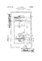
- y Figure 1 is a view partly in section and partly in plan of a metal-working machine such as va co'ld header, having the present improvements.
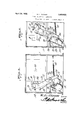
- Figure 2 is a vertical transverse section through the machine showing the cut-ofi'l position.
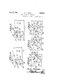
- FIG. 8 illustrates the parts returning to their place of starting.
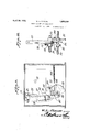
- Figure 9 is a view partly in section and '50Y partly in elevation ofja modified mechanism.
- Figure 7 shows the fourth or releasedv Figure 10 is a side view of the mechanism shown in Figure 9.
- Figure 11 is a view similar to Figure 9 showing another form of the machine.
- Figure 12 is a like view showing the mechanism in other positions.
- 1 designates the body of a metalworking machine, such as a cold header,'havf ing a heading slide 2 carrying a shaping die M 3.
- This slide can be operated by any'suitableQmeans driven by a main shaft-4 which is operatively connected, as b gears 5 and 6, to a transverse timer shaft
- the timer shaft is adapted to transmit mou tion through gears 8 and 9 to a cam shaft 10 which, in the structure illustrated, in Figures 1 to 8, carries three cams 11, 12, and 13.
- a rock shaft 14 is journaled close to the cams and carries an arml 15 in which a cut-off die or shear element 16 is mounted.
- This die can be supported in a slot 17 and bear a ainst an adjusting screw 18, whereby the die can be advanced or retracted relative to its carrying arm 15.
- the active edge of the movable cut-oftl die 16 is adapted to work close to and across a stationary shearing or cut-of die 19. located at the point where stock is fed into the machine. It is'adapted to travel to a point close tothe stationary shaping die indicated generally at 20
- the rock shaft 14 has arms 21 and 22 extending therefrom' and adapted, res ectively, to advance the carrying arm 15 rom its 35 initial position shown in Figure 4 and return it to said position.
- ⁇ Arm 21 has a roller 23 for engaging the periphery of cam 11 while arm 22 has a roller 24 for engaging cam 12.
- a spring 25 connected to arm 22 acts to hold roller 23 normally in contactpwith cam 11.
- a gripper including a-lever 26 and a jaw 27 is fulcrumed onthe carrying arm 15 and a rod 28 connects' this lever to a'levetr 29 carrying a roller 30 adapted to engage the cam 95 13.
- a spring 31 acts to draw lever 29 downwardly and shift the jaw 27toward die 16.
- Stock S in the form of a wire or bar is adapted tobe fed a desired distance into the machine while the parts are positioned vas shown in Figure 4.
- the several cams are so timed that immediately following the insertion of the stock cam 13 will move from engagement with roller 30 so that spring 31 will shift the jaw 27 of the gripper and cause it to bind on the projecting stock as shown in Figures 2 and 5.
- cam 11 comes into action and, while cam 13 is clear of roller 30, arm 21 will be shifted to swing the carrying arm 15 to the position shown in Figures 3 and 6.
- the blank B will be sheared from the stock and carried to position directly in front of the recess in stationary shaping die as shown in Figure 6..
- the heading slide is advancing toward its work which is engaged by die 3 and pressed into die 20.
- cam 13 shifts lever 29 to quickly swing jaw 27 away from the blank.
- the carrying arm is in the form of a slide 45 on which a lever 46 is fulcrumed.
- This lever carries a gripper jaw 47 and a spring 48 serves to hold the j aw nor- -mally in gripping position.
- a cam 49 on shaft 50 acts to reciprocate the slide and anothercam 51 operates the gripper jaw through lever 46. i
- the slide and jaw can be shifted in properly timed relation to the heading slide to shear off a blank, carry it to the shaping die 20 as in Figure 12,'release the blank, and ret-urn to the point of starting.
- a carry-over including amovable member, a shearing die and a gripper each carried solely by said member, the gripper being pivoted on the member at a point removed from the point of support of the member and being movable with said member and relative to the shearing die, cam operated means for shifting the movable member to cut ofll a blank, force it to the stationary shaping die for engagement by the movable shaping die, and return to the point of starting, and cam operated means for imparting an abrupt swinging movement to the gripper relative to the movable member to grip a blank upon the shearing die and lhold it during the transfer operation, and
- a carry-over for metal-working machines including a member mounted for back and forth movement, a shearing element carried bythe member, a gripper pivoted on said member at a point remote from the point of support of the member and movable with the member, said gripper including a jaw movable relative to the shearing element, and continuously rotatable means for shifting said member and gripper to successively grip, shear, carry, and release Va blank engaged thereby.
- a carry-over for metal-working machines including a member mounted for back and forth movement, a shearing element carried thereby, a gripper pivotedl on the member at a ⁇ point remote ⁇ from the point of support of the lmember and movable with said member, said gripper including a jaw movable about the pivot 0f the gripper 'relative to the shearing element, cams mounted for continuous rotation, and means actuated by the cams-l for shifting said member and gripper in properly time relation to successively grip, shear, carry, and release a blank engaged thereby.
Landscapes
- Engineering & Computer Science (AREA)
- Mechanical Engineering (AREA)
- Forging (AREA)
Description
April 26, 1932. w. l.. cLoUsE BLANK CUT-OFF AQD CARRY-OVER 5 Sheets-Sheet l Fil'ed Nov. lO, 1930 www@ April 26, 1932 w. l.. cLoUsE 1,856,028
BLANK CUT-OFF AND CRRYOVER Filed Nov. lo, 1950 5 Sheets-Sheet 3 April 26, 1932. W CLOUSE 1,856,028
BLANK CUT-OFF AND CARRY-OVER Filed Nov, 10, 1930 5 Sheets-Sheet 4 rig/19.3,
April 26,1932- w. l.. cLoUsE 1,856,028
BLANK CUT-OFF AND CARRY-OVER Filed Nov. l0, 1930 5 Sheets-Sheet 5 JHMWL WTL. 20u56 IW'UWM 4 a ttomqo.
Patented Apr. 26, 1932 Lsaoza UNITED sTATEs PATENT OFFICE WILLIAM I. CLOUSE, 02B' TIFFIN, OHIO, ASSIGNOR T0 THE NATIONAL MACHINERY GOII- l PANY, F TIFFIN, OHIO BLANK CUT-0FF AND CARRY-OVER Application med November 10, 1930. Serial No. 494,791.
This invention relates to a blank cut-olf and carry-over for metal-working machlnes such as cold headers, forging machines, etc.
It is an object of the invention to providea simple and efficient mechanism whereby a blank can be cut from alength of stock, tightly gripped, and then carried to positlon for engagement by the sha-ping, dies.
Another object is to provide a structure of this nature having continuously rotating means for actuating it in properly timed relation to the movable shaping die or dies. With the foregoing and other objects in view which will appear as the description proceeds, the invention resides in the combination and arrangement of parts and in the details of construction hereinafter described and claimed, it being understood that changes in the precise embodiment of the invention herein disclosed may be made within the scope of what is claimed without departing from the spirit of the invention.
In the accompanying drawings the preferred form of the invention has been shown.
In said drawings: y Figure 1 is a view partly in section and partly in plan of a metal-working machine such as va co'ld header, having the present improvements.
Figure 2 is a vertical transverse section through the machine showing the cut-ofi'l position.
Figure 8 illustrates the parts returning to their place of starting.
Figure 9 is a view partly in section and '50Y partly in elevation ofja modified mechanism.
Figure 7 shows the fourth or releasedv Figure 10 is a side view of the mechanism shown in Figure 9. v
Figure 11 is a view similar to Figure 9 showing another form of the machine.
Figure 12 is a like view showing the mechanism in other positions.
Referring to the figures by characters of reference, 1 designates the body of a metalworking machine, such as a cold header,'havf ing a heading slide 2 carrying a shaping die M 3. This slide can be operated by any'suitableQmeans driven by a main shaft-4 which is operatively connected, as b gears 5 and 6, to a transverse timer shaft The timer shaft is adapted to transmit mou tion through gears 8 and 9 to a cam shaft 10 which, in the structure illustrated, in Figures 1 to 8, carries three cams 11, 12, and 13. A rock shaft 14 is journaled close to the cams and carries an arml 15 in which a cut-off die or shear element 16 is mounted. This die can be supported in a slot 17 and bear a ainst an adjusting screw 18, whereby the die can be advanced or retracted relative to its carrying arm 15.
The active edge of the movable cut-oftl die 16 is adapted to work close to and across a stationary shearing or cut-of die 19. located at the point where stock is fed into the machine. It is'adapted to travel to a point close tothe stationary shaping die indicated generally at 20 The rock shaft 14 has arms 21 and 22 extending therefrom' and adapted, res ectively, to advance the carrying arm 15 rom its 35 initial position shown in Figure 4 and return it to said position. `Arm 21 has a roller 23 for engaging the periphery of cam 11 while arm 22 has a roller 24 for engaging cam 12. A spring 25 connected to arm 22 acts to hold roller 23 normally in contactpwith cam 11.
A gripper including a-lever 26 and a jaw 27 is fulcrumed onthe carrying arm 15 and a rod 28 connects' this lever to a'levetr 29 carrying a roller 30 adapted to engage the cam 95 13. A spring 31 acts to draw lever 29 downwardly and shift the jaw 27toward die 16.
Stock S in the form of a wire or bar is adapted tobe fed a desired distance into the machine while the parts are positioned vas shown in Figure 4. The several cams are so timed that immediately following the insertion of the stock cam 13 will move from engagement with roller 30 so that spring 31 will shift the jaw 27 of the gripper and cause it to bind on the projecting stock as shown in Figures 2 and 5.
Thereafter cam 11 comes into action and, while cam 13 is clear of roller 30, arm 21 will be shifted to swing the carrying arm 15 to the position shown in Figures 3 and 6. Thus the blank B will be sheared from the stock and carried to position directly in front of the recess in stationary shaping die as shown in Figure 6.. During this operation the heading slide is advancing toward its work which is engaged by die 3 and pressed into die 20. Closely following Contact with the blank by die 3 cam 13 shifts lever 29 to quickly swing jaw 27 away from the blank.
(see the dotted position in Figure 3 and full position in Figure 7), this operation being quickly followed by the action of cam 12 on arm 22 to swing back the arm 15 as in Figure 8 and then to its initial position shown lin Figure 4.
The action of the parts illustrated in Fig- 'ures 6, 7, and 8, occurs before the'die 3 can strike the die 16 and jaw 27 but following the contact of die 3 .with the blank. This necessitates very quick action which, however, is
y,described can be modified in many ways and the same results obtained. In Figures 9 and 10 asimplified arrangement has been illustrated. This includes cams 32, 33, and 34 carried by shaft 35 which correspond with cams 11, 12, and 13, and shaft 10. A rock shaft 36 has a carrying arm 37 and the gripper jaw 38 is carried by a lever 39, one arm of which is provided with a roller 40 for e'ngaging cam 34'.v A spring 41 connects levers 37 and 39 for holding the jaw 38 normally 1n gripping position. Arms 42 and 43 are adapted to be actuated by cams 32 and 33 respectively and a spring 44 exerts aconstant pull on arm 42. These parts all operate in properly timed relation tothe heading slide to cut-off, carry-over, and release a blank in the manner heretofore described.
In Figures 11 vand 12 the carrying arm is in the form of a slide 45 on which a lever 46 is fulcrumed. This lever carries a gripper jaw 47 and a spring 48 serves to hold the j aw nor- -mally in gripping position.. A cam 49 on shaft 50 acts to reciprocate the slide and anothercam 51 operates the gripper jaw through lever 46. i Thus the slide and jaw can be shifted in properly timed relation to the heading slide to shear off a blank, carry it to the shaping die 20 as in Figure 12,'release the blank, and ret-urn to the point of starting.
As before stated other means can be employed for shearing, carrying, and releasing the blank'in the timed relation described without departing from the spirit ofthe inven tion as claimed'.
What is claimed is:
1. In a metal-working machine the combination with stationary and movable shaping dies, of continuouslyrotating cams operating in timed relation to the movable die, a carry-over including amovable member, a shearing die and a gripper each carried solely by said member, the gripper being pivoted on the member at a point removed from the point of support of the member and being movable with said member and relative to the shearing die, cam operated means for shifting the movable member to cut ofll a blank, force it to the stationary shaping die for engagement by the movable shaping die, and return to the point of starting, and cam operated means for imparting an abrupt swinging movement to the gripper relative to the movable member to grip a blank upon the shearing die and lhold it during the transfer operation, and
thereafter abruptly release the blank, and return with the movable member, all in properly timed relation.
2. A carry-over for metal-working machines including a member mounted for back and forth movement, a shearing element carried bythe member, a gripper pivoted on said member at a point remote from the point of support of the member and movable with the member, said gripper including a jaw movable relative to the shearing element, and continuously rotatable means for shifting said member and gripper to successively grip, shear, carry, and release Va blank engaged thereby.
3. A carry-over for metal-working machines including a member mounted for back and forth movement, a shearing element carried thereby, a gripper pivotedl on the member at a` point remote` from the point of support of the lmember and movable with said member, said gripper including a jaw movable about the pivot 0f the gripper 'relative to the shearing element, cams mounted for continuous rotation, and means actuated by the cams-l for shifting said member and gripper in properly time relation to successively grip, shear, carry, and release a blank engaged thereby.
4. The combination with stationary and movable shaping dies of a metal-working machine, of a carryover including a member mounted for back and forth movement between4 said dies, a shearing element carried thereby, a gripper movable with said member and pivoted thereon at a point removed from the point of support of the member, said gripper including a jaw movable relative to the shearing element about the pivot of the gripper, cams mounted for continuous rotation in properly time relation to the movable shaping die, and means operated by the respective cams for shifting said member and gripper in properly timed relation to successively grip and shear a blank, convey it to `the stationary shaping .die for engagement by the movable shaping die, and then release the blank and return to the point of starting.
In testimony that I claim the foregoing as my own, I have hereto alxed my signature.
WILLIAM L. CLOUSE.
Priority Applications (1)
| Application Number | Priority Date | Filing Date | Title |
|---|---|---|---|
| US494791A US1856028A (en) | 1930-11-10 | 1930-11-10 | Blank cut-off and carry-over |
Applications Claiming Priority (1)
| Application Number | Priority Date | Filing Date | Title |
|---|---|---|---|
| US494791A US1856028A (en) | 1930-11-10 | 1930-11-10 | Blank cut-off and carry-over |
Publications (1)
| Publication Number | Publication Date |
|---|---|
| US1856028A true US1856028A (en) | 1932-04-26 |
Family
ID=23965986
Family Applications (1)
| Application Number | Title | Priority Date | Filing Date |
|---|---|---|---|
| US494791A Expired - Lifetime US1856028A (en) | 1930-11-10 | 1930-11-10 | Blank cut-off and carry-over |
Country Status (1)
| Country | Link |
|---|---|
| US (1) | US1856028A (en) |
Cited By (2)
| Publication number | Priority date | Publication date | Assignee | Title |
|---|---|---|---|---|
| US2613776A (en) * | 1946-04-08 | 1952-10-14 | Nat Machinery Co | Feed clutch for cold headers |
| DE1270934B (en) * | 1960-02-09 | 1968-06-20 | Textron Inc | Shearing device on upsetting presses for bolts u. like |
-
1930
- 1930-11-10 US US494791A patent/US1856028A/en not_active Expired - Lifetime
Cited By (2)
| Publication number | Priority date | Publication date | Assignee | Title |
|---|---|---|---|---|
| US2613776A (en) * | 1946-04-08 | 1952-10-14 | Nat Machinery Co | Feed clutch for cold headers |
| DE1270934B (en) * | 1960-02-09 | 1968-06-20 | Textron Inc | Shearing device on upsetting presses for bolts u. like |
Similar Documents
| Publication | Publication Date | Title |
|---|---|---|
| US1856028A (en) | Blank cut-off and carry-over | |
| US2074680A (en) | Upsetting machine | |
| US2272592A (en) | Transfer mechanism | |
| US2026823A (en) | Bolt making machine | |
| US1766484A (en) | Header | |
| US1314037A (en) | op chicago | |
| US2318825A (en) | Cutoff and transfer mechanism | |
| US699508A (en) | Gripping mechanism for feeding metal strips, &c. | |
| US1774915A (en) | Machine for making spikes | |
| US1856027A (en) | Feeding mechanism for metal working machines | |
| US1244912A (en) | Heading-machine. | |
| US3158047A (en) | Machine for making headed articles | |
| US1685377A (en) | Cut-off mechanism for metal-working machines | |
| US2038541A (en) | Machine for making bolts and the like | |
| US422151A (en) | Machine for making spikes | |
| US341970A (en) | Bolt blank machine | |
| US1405174A (en) | Header | |
| US435256A (en) | Wire-nail machine | |
| US1242199A (en) | Nut-machine. | |
| US1251652A (en) | Die for rivet and nail machines. | |
| US53782A (en) | Improvement in nut-machines | |
| US1437578A (en) | Feed stop | |
| US1241693A (en) | Header. | |
| US3117328A (en) | Machine for hot forming scale free metallic articles | |
| US1989398A (en) | Cut-off mechanism for heading machines |