US1856027A - Feeding mechanism for metal working machines - Google Patents
Feeding mechanism for metal working machines Download PDFInfo
- Publication number
- US1856027A US1856027A US494786A US49478630A US1856027A US 1856027 A US1856027 A US 1856027A US 494786 A US494786 A US 494786A US 49478630 A US49478630 A US 49478630A US 1856027 A US1856027 A US 1856027A
- Authority
- US
- United States
- Prior art keywords
- stock
- feeding
- drive
- key
- feeding mechanism
- Prior art date
- Legal status (The legal status is an assumption and is not a legal conclusion. Google has not performed a legal analysis and makes no representation as to the accuracy of the status listed.)
- Expired - Lifetime
Links
- 230000007246 mechanism Effects 0.000 title description 66
- 238000005555 metalworking Methods 0.000 title description 7
- 230000008878 coupling Effects 0.000 description 16
- 238000010168 coupling process Methods 0.000 description 16
- 238000005859 coupling reaction Methods 0.000 description 16
- 230000010355 oscillation Effects 0.000 description 9
- 239000002699 waste material Substances 0.000 description 6
- 230000000452 restraining effect Effects 0.000 description 4
- 238000010008 shearing Methods 0.000 description 4
- 238000000034 method Methods 0.000 description 3
- 238000010276 construction Methods 0.000 description 1
- 238000010586 diagram Methods 0.000 description 1
- 238000005242 forging Methods 0.000 description 1
- 238000004519 manufacturing process Methods 0.000 description 1
- 239000000463 material Substances 0.000 description 1
- 230000002028 premature Effects 0.000 description 1
- 238000007493 shaping process Methods 0.000 description 1
Images
Classifications
-
- B—PERFORMING OPERATIONS; TRANSPORTING
- B21—MECHANICAL METAL-WORKING WITHOUT ESSENTIALLY REMOVING MATERIAL; PUNCHING METAL
- B21K—MAKING FORGED OR PRESSED METAL PRODUCTS, e.g. HORSE-SHOES, RIVETS, BOLTS OR WHEELS
- B21K27/00—Handling devices, e.g. for feeding, aligning, discharging, Cutting-off means; Arrangement thereof
- B21K27/02—Feeding devices for rods, wire, or strips
Definitions
- This invention relates to mechanism for It is a further object to provide feed mechfeeding stock to metal Working machines such anism which is simple and compact in conas headers, forging machines, etc. struction and will operate efficiently to trans-
- metal Working machines such anism which is simple and compact in conas headers, forging machines, etc. struction and will operate efficiently to trans-
- These machines are generally equipped mit motion from a rotary driving element sowith driving mechanism for continuously reas to feed stock intermittently but always the ciprocating the heading slide, and a feed same distance.
- mechanism operatively connected to the clriv- With the foregoing and other objects in ing mechanism.
- the stock is usually in wire view which will appear as the description or rod form and the feed mechanism moves it proceeds, the invention resides in the combi- 19 with an intermittent motion into the machine nation and arrangement of parts and in the where blanks are cut off and shaped.
- Figure 1 is a side elevation showing in outquired. Otherwise the entire length of stock, line a header having applied to it the feed with the exception of a short end, would be mechanism constituting the present invenused before a new supply could be started. tion.
- Figure 2 is a side elevation of the coupling 25 stock because as much as two or more lengths mechanism, its tripping means being shown have necessarily been cut off undersize by adjacent thereto.
- successive shearing operations before the ma- Figure 3 i a, tion on li 3-3, Figu 2, chine could again start to function properly-
- Figure 4 is a section on line el4t, Figure 2.
- Fi 4 30 provide a means for automatically stopping Figur 6 i an inn l ti f th d i the feeding mechanism when the end of the plat f th mecha i stock reaches a predetermined point, thereby Fi re 7 is a detail view of the coupling enabling the operator to start a new supply key.
- FIG. 9 is a view partly in front elevation shearing operation and Wlll be equal to the and partly in Section of portion of a fi of f y Smgle' Thlawasteg chine showing automatic controlling means.
- Figure 10 is a Si (19 elevation of the coupling Portlons of the two lengths of stock mechanism partly broken away and having Another object of the present invention is c nne to provide a novel feed mechanism for interi 0 ctlon for the automatlc control them mittently actuating the stock, the construc- 45 tion being such that although the mechanism Flgure 1S a P Partly m 560E191 ⁇ ?
- Figure 13 is a similar view showing how waste is reduced by the present means.
- 1 designates the drive shaft of the machine which is adapted to operate a heat.- ing slide, not shown.
- a countershaft or timer shaft 2 is operatively connected to shaft 1 by gears 3 and has any suitable means, such as a crank 4, whereby the feeding mechanism will be operated synchronously with the heading slide.
- the feed rolls for engaging a length of stock S have been designated at 5 and 6 can be operatively connected by gears or other suitable means, not shown, for insuring simultaneous rotation.
- a shaft 7 can be connected directly to one of the rolls or gearing can be used for transmitting motion from the shaft to the rolls as will be obvious.
- a driven clutch member 8 having an annular flange 9 adapted to extend around a driving clutch member 10 in the periphery of which are angular recesses 11 holding rollers 12. These rollers act to grip and rotate the member 8 when member 10 is rotated in one direction. However, the member 10 c n rotate in the opposite or clockwise direction independently of member 8.
- driving clutch member 10 has a radially disposed guide 13 in which is mounted a slidable key 14 the outer end of which has a laterally extended wedge 15. The outer face of the wedge is beveled as shown at 16. A spring 17 seated in the guide 13 bears against the key to hold it normally pressed outwardly from the shaft 7.
- a drive plate 18 having a crank extension 19 connected by a rod 20 to the crank 4.
- This plate can lit snugly against clutch member 10 and has a segmental recess 21 in its inner face in which the guide 13 is mounted for oscillation.
- a marginal flange 22 is extended from the plate at the recess and has a laterally extended rim 23 one end 24: of which is so spaced from one wall of recess 21 as to allow the outer end of key 14 to lap it when guide 18 is seated against the recess wall.
- This arrangementof the parts has been shown in Figure 6 and it will be ob vious that it results in locking together the plate 18 and member 10 so that they can not rotate independently of each other.
- the wedge extends laterally beyond the rim 23 as illustrated in Figure 4, but the distance between this rim and the periphery of flange 9 is slightly greater than the thickness of the wedge so that, should the key 1% .be pressed inwardly against its spring 17, the wedge would be removed inwardly from the end of rim 23.
- the machine which can include a heading slide, will operate continuously and the gears can be so timed as to produce one rotation of crank 4 to any desired number of rotations of the shaft 1.
- the gears can be so timed as to produce one rotation of crank 4 to any desired number of rotations of the shaft 1.
- the shaft 1 for operating the heading slide would make two complete rotations to one rotation of shaft 2 which drives the feeding mechanism.
- a tripping shaft 25 is mounted for rotation near the plate 18 and has a tripping finger 26 adapted to be swung into and out of the path of wedge 15. The finger is located where it will be engagec by the wedge when one of its extreme -positions is reached.
- An arm 27 extends from snaft 25 and by means thereof the shaft can be rotated by hand or by mechanism provided for that purpose.
- This mechanism includes a shaft 31 journaled at any suitable point adjacent to the place where the stock enters the machine, there being an arm 32 extended from the shaft and having a latch 33 pivotally connected to it.
- This latch which is adapted to rest on the stock S, has a shoulder 34 which thrusts laterally against the stock.
- a suitable guide 35 can be provided for the latch and 'a spring 36, coiled about the shaft, can be used for holding the shoulder 34 normally pressed against the stock.
- Another arm 37 is extended from shaft 31 and bears against one end of a push rod 38 mounted in a guide 39 and pivotally connected to an arm 40 extending from tripping shaft 25. 7
- the combination with a continuously operating drive mechanism including an oscillating member, of feeding means, cooperating drive and driven clutch members for operating the feeding means in one direction only, means released by the oscillating member when reaching one limit of its movement, for coupling it to the drive clutch member for joint reciprocation, and means for disengaging the coupling means from the oscillating member to permit continued movement thereof independently of the clutch members.
- a continuously operating drive mechanism including an oscillating member, of feeding means, cooperating drive and driven clutch members for operating the feeding means in one direction only, a key carried by the drive clutch member, means on the oscillating member for holding the key under restraint, means for shifting the key into the path of said restraining means when the oscillating member reaches one limit of its movement, thereby to couple said member to the drive coupling member, for joint reciprocation, a tripping element, and means for moving said element into the path of the key to shift it from the path of the restraining means and hold it during independent movement of the oscillating member.
- the combination with feeding mechanism including a driving clutch member and a driven clutch member adapted to be moved thereby in one direction only, of a key rotatable with and slidable relative to the driving clutch member, a driving member mounted for continuous oscillation having a recess for holding the key during oscillation of said member relative to the clutch members, and co-operating means on the oscillating member and the driving clutch member for placing the key in looking engagement with the oscillating member when said member reaches one extreme position during its oscillation.
- a driving element means operated thereby for feeding stock intermittently into the machine, and means normally restrained by the stock for uncoupling the feeding means from the driving element when the stock becomes disengaged from said restrained means.
- a continuously operating drive mechanism including an oscillating member, of feeding means, cooperating drive and driven clutch members for operating the feeding means in one direction only, and means released by the oscillating member when reaching one limit of its movement, for coupling it to the drive clutch member for joint reciprocation, said means including a stock restrained element, and means for automatically shift-ing said element, when disengaged from the stock.
- a stock-feeding mechanism for driving said feeding mechanism with intermittent strokes to feed equal lengths of stock to the machine, means for coupling the operating mechanism to the feeding mechanism solely at the beginning of one full stroke of the feeding mechanism, and means for uncoupling said mechanism solely at the end of one full stroke of the feeding mechanism.
- a stock-feeding mechanism for driving said feeding mechanism with intermittent strokes to feed equal lengths of stock to the machine, means for coupling the operating mechanism to the feeding mechanism solely at the beginning of one full stroke of the feeding mechanism, and means automatically released When the end of a length of stock reaches a predetermined point for uncoupling said mechanisms solely at the end of one full stroke of the feeding mechanism.
Landscapes
- Engineering & Computer Science (AREA)
- Mechanical Engineering (AREA)
- Press Drives And Press Lines (AREA)
Description
April 1932- w. L. CLOUSE 1,856,027
FEEDING MECHANISM FOR METAL WORKING MACHINES Filed Nov. 10, 1930 4 Sheets-Sheet 1 WIL.CZouS0 3 W. L. CLOUSE April 26, 1932.,
FEEDING MECHANISM FOR METAL WORKING MACHINES Filed NOV. 10, 1930 4 Sheets-Sheet 2 l lll w April 26, 1932. 1,856,027
FEEDING MECHANISM FOR METAL WORKING MACHINES W. L. CLOUSE Filed Nov. 10, 1930 4 Sheets-Sheet 3 April 26, 1932. w. L CLOUSE 1,856,027
FEEDING MECHANISM FOR METAL WORKINGJMACHINES Filed Nov. 10, 1930 4 Sheets-Sheet 4 abhor/mg;
Patented Apr. 26, 1932 UNITED STATES PATENT OFFICE WILLIAM L. CLQUSE, F TIFFIN, OHIO, ASSIGNOR TO THE NATIONAL MACHINERY COMPANY, OF TIFFIN, OHIO FEEDING MECHANISM FOR METAL WORKING MACHINES Application filed November 10, 1930. Serial No. 494,786.
This invention relates to mechanism for It is a further object to provide feed mechfeeding stock to metal Working machines such anism which is simple and compact in conas headers, forging machines, etc. struction and will operate efficiently to trans- These machines are generally equipped mit motion from a rotary driving element sowith driving mechanism for continuously reas to feed stock intermittently but always the ciprocating the heading slide, and a feed same distance. mechanism operatively connected to the clriv- With the foregoing and other objects in ing mechanism. The stock is usually in wire view which will appear as the description or rod form and the feed mechanism moves it proceeds, the invention resides in the combi- 19 with an intermittent motion into the machine nation and arrangement of parts and in the where blanks are cut off and shaped. It fredetails of construction hereinafter described quently happens that the feed mechanism is and claimed, it being understood that changes automatically uncoupled from the driving in the precise embodiment of the invention mechanism by relief means. The operator herein disclosed maybe made within the scope is also finds it necessary from time to time to unof what is claimed without departing from the couple the feeding mechanism from the drivspirit of the invention. ing mechanism. In the accompanying drawings the pre- Furthermore, during the feeding of stock ferred form of the invention has been shown. to the shearing or shaping mechanism of the In said drawings:
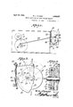
20 machine extreme watchfulness has been re- Figure 1 is a side elevation showing in outquired. Otherwise the entire length of stock, line a header having applied to it the feed with the exception of a short end, would be mechanism constituting the present invenused before a new supply could be started. tion.
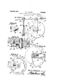
This has resulted in undesirable waste of Figure 2 is a side elevation of the coupling 25 stock because as much as two or more lengths mechanism, its tripping means being shown have necessarily been cut off undersize by adjacent thereto. successive shearing operations before the ma- Figure 3 i a, tion on li 3-3, Figu 2, chine could again start to function properly- Figure 4 is a section on line el4t, Figure 2.
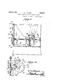
It is an object of the present invention to Fi r 5 i a ti on li 5 5, Fi 4 30 provide a means for automatically stopping Figur 6 i an inn l ti f th d i the feeding mechanism when the end of the plat f th mecha i stock reaches a predetermined point, thereby Fi re 7 is a detail view of the coupling enabling the operator to start a new supply key. of stock in contact with the end of the stock in Fig 8 i a i i il t Fi 1 35 advance thereof, so that, when the feedmg h i th l ti positions f th parts mechanism is again started, the maxlmum While being t i d Waste resulting ,Will W'Q y Single Figure 9 is a view partly in front elevation shearing operation and Wlll be equal to the and partly in Section of portion of a fi of f y Smgle' Thlawasteg chine showing automatic controlling means.
40 portion vriil be composed o t e meetlng en Figure 10 is a Si (19 elevation of the coupling Portlons of the two lengths of stock mechanism partly broken away and having Another object of the present invention is c nne to provide a novel feed mechanism for interi 0 ctlon for the automatlc control them mittently actuating the stock, the construc- 45 tion being such that although the mechanism Flgure 1S a P Partly m 560E191}? can betripped or uncoupled from the drivof machme havlng lmprovedautomatlc ing mechanism at will, it will always pick up p for the g Q Q or startfeeding the stock only at such time as lg le 121s a VleW lllustratmg 1n diagram to insure feeding the correct length into the t e e ults Obtained by old methods of feed- Ec machine to produce a blank of the desired size. mg stock.
Figure 13 is a similar view showing how waste is reduced by the present means.
Referring to the figures by characters of reference, 1 designates the drive shaft of the machine which is adapted to operate a heat.- ing slide, not shown. A countershaft or timer shaft 2 is operatively connected to shaft 1 by gears 3 and has any suitable means, such as a crank 4, whereby the feeding mechanism will be operated synchronously with the heading slide.
The feed rolls for engaging a length of stock S have been designated at 5 and 6 can be operatively connected by gears or other suitable means, not shown, for insuring simultaneous rotation.
A shaft 7 can be connected directly to one of the rolls or gearing can be used for transmitting motion from the shaft to the rolls as will be obvious. To this shaft is fixedly connected a driven clutch member 8 having an annular flange 9 adapted to extend around a driving clutch member 10 in the periphery of which are angular recesses 11 holding rollers 12. These rollers act to grip and rotate the member 8 when member 10 is rotated in one direction. However, the member 10 c n rotate in the opposite or clockwise direction independently of member 8.
One face of driving clutch member 10 has a radially disposed guide 13 in which is mounted a slidable key 14 the outer end of which has a laterally extended wedge 15. The outer face of the wedge is beveled as shown at 16. A spring 17 seated in the guide 13 bears against the key to hold it normally pressed outwardly from the shaft 7.
Mounted to oscillate on the shaft a drive plate 18 having a crank extension 19 connected by a rod 20 to the crank 4. This plate can lit snugly against clutch member 10 and has a segmental recess 21 in its inner face in which the guide 13 is mounted for oscillation. A marginal flange 22 is extended from the plate at the recess and has a laterally extended rim 23 one end 24: of which is so spaced from one wall of recess 21 as to allow the outer end of key 14 to lap it when guide 18 is seated against the recess wall. This arrangementof the parts has been shown in Figure 6 and it will be ob vious that it results in locking together the plate 18 and member 10 so that they can not rotate independently of each other. The wedge extends laterally beyond the rim 23 as illustrated in Figure 4, but the distance between this rim and the periphery of flange 9 is slightly greater than the thickness of the wedge so that, should the key 1% .be pressed inwardly against its spring 17, the wedge would be removed inwardly from the end of rim 23.
In operation the machine, which can include a heading slide, will operate continu ously and the gears can be so timed as to produce one rotation of crank 4 to any desired number of rotations of the shaft 1. For example in a two-blow cold header the shaft 1 for operating the heading slide would make two complete rotations to one rotation of shaft 2 which drives the feeding mechanism.
[is the crank l is rotated in a counterclockwise direction motion will be transmitted therefrom through rod to crank extension 19, so that wall 21 of recess 21 will thrust against guide 13 and positively actuate the feeding mechanism to positively advance stock the required distance into the machine. If the key 14: is seated. in locking position as in Figure 6 the plate 18 will cause the drive member 10 of the clutch to rotate therewith in a clockwise direction. During every movcment of plate 18 and member 10 in a clockwise direction the rollers 12 will move freely relative to flange 9 so that clutch member 8 will not be actuated. During their move- I in counterclockwise direction with the positively driven member 10, however,
he rollers will take hold of the flange 9 and cause the clutch member 8 to rotate with the parts 10 and 18, thereby actuating shaft Z" and the feed rolls 5 and 6. This will cause the stock S to be fed into the machine disdetermined by the arc of movement of the clutch members. This intermittent advancement of or feeding of the stock will continue as long as the clutch connection is not interfered with.
For the pur'iose of uncoupling the feed from its drive mechanism a tripping shaft 25 is mounted for rotation near the plate 18 and has a tripping finger 26 adapted to be swung into and out of the path of wedge 15. The finger is located where it will be engagec by the wedge when one of its extreme -positions is reached. An arm 27 extends from snaft 25 and by means thereof the shaft can be rotated by hand or by mechanism provided for that purpose.
lVhen it is desired to uncouple the feeding mechanism from its driving mechanism the shaft 25 is rotated to swing finger to one extreme position. This will bring it into the path of the wedge 15, the beveled face of which will bear against finger 26, and press the wedge and key 141: inwardly out of engagement with the end 24- of rim Thus as the extension 19 on plate 18 moves from position, a in Figure l to position 7) the wedge will be left in engagement with the tripping finger, and as the recess 21 is of such area as to permit relative oscillation of the plate 18, the continued oscillation of said plate will not actuate the clutch member 10.
\Vhen it is desired to couple the feed mechanism to the crive mechanism the tripp ng finger 26 is moved away from the key. The plate 18 will continue to move independently of the clutch member 10 until, at one limit of its movement the end or shoulder 24 is moved past the key. At that time the key 14, which has been pressed lightly by its spring 17 against rim'23 but held against movement therewith by the feed rolls 5 and 6 and their connections, will shift outwardly into the path of the rim 23. Thus as theplate 18 begins its return or clockwise movement, the clutch member 10 will be coupled thereto but will rotate independently ofmember 8. On the next or counterclockwise movement of the parts the wall 21 willthrust against guide 13 and a correct length of stock will be fed positively into the machine.
It will be noted that the feeding of the stock can commence only when the plate 18 reaches one extreme position. Consequently,
as premature starting and stopping is avoided, short lengths of stock will not be delivered into the machine and there will be no undesirable waste.
Should it be desired to stop the feeding mechanism automatically when the length of stock is nearly exhausted, a mechanism such as shown in Figures 9 to 11 inclusive can be used. This mechanism includes a shaft 31 journaled at any suitable point adjacent to the place where the stock enters the machine, there being an arm 32 extended from the shaft and having a latch 33 pivotally connected to it. This latch, which is adapted to rest on the stock S, has a shoulder 34 which thrusts laterally against the stock. A suitable guide 35 can be provided for the latch and 'a spring 36, coiled about the shaft, can be used for holding the shoulder 34 normally pressed against the stock.
Another arm 37 is extended from shaft 31 and bears against one end of a push rod 38 mounted in a guide 39 and pivotally connected to an arm 40 extending from tripping shaft 25. 7
Normally the latch is held against movement by the stock S as shown in Figures 9 and 11 andat that time the tripping finger 26 is held out of the path of wedge 15. Consequently the oscillation of plate 18 will cause intermittent rotation of shaft 7 and wheel 30 so that stock S will be fed into the machine in uniform blank lengths.
When the end of the stock passes from the end of the latch 33, the spring 36 will rotate shaft 31 and cause arm 37 to press against rod 38. Thus arm 40 will be shifted to rotate shaft 25 and bring finger 26 into the path of wedge 15. This will cause the plate 18 to be uncoupled from the shaft and further oscillation of the plate will be without efiect after it reaches one limit of its movement, at which time the stock S will be supported flush with the plane X in which the last blank was cut off.
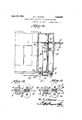
As the feeding mechanism is thus stopped automatically with a portion of the stock S still gripped by its feeding means, the end of another length of stock can be placed thereagainst as indicated at y in Figure 13. The tripping shaft can then be shifted by hand to release wedge 15 and at the beginning of the next clockwise stroke of plate 18 it will pick up key 1 1 and the drive member 10 and carry them in a clockwise direction. Thus on the next counterclockwise movement of the parts the wall 21 thrusting against guide 13, and the rollers 12 cooperating with flange 9 will feed the stock into the machine positively a distance equal to one full-length blank, as shown at A. Successive actuations of the stock will feed other full blank-lengths of stock as indicated, for example, at B, C, D, E and F. The next full blank-length of stock will consist, probably, of two short lengths, G and H, which comprise the meeting end portions of the two lengths of stock when these are cut off. They will constitute the only waste of stock which will occur until another supply is fed to the machine.
In old methods of feeding the stock has been directed intermittently into the machine until the end has passed from between the feeding wheels or rolls. One end has thus been left spaced from the rolls as shown at a in Figure 12 and the other end frequently stops short of the gage 29 or else hits it and rebounds therefrom (see Figure 12). The operators attention is attracted by the fact that production has stopped. He therefore starts the end of another length of stock between the feed rolls. This will not start the old stock forward until it comes thereagainst, thereby losing an interval in the timed operation of the mechanism. The short blank a will be cut off and before the advancing end of the old stock reaches the stop or gage 29 another short length I) will be sheared off. Thereafter other lengths of proper size will be cut as indicated at 0 and d, but when the abutting ends of the old and new stock are fed to the shearing mechanism two short lengths e and f will be cut off, these totaling in length one full size blank. Thus under old methods as illustrated in Figure 12, the waste of material will always be greater than one full size blank while by using an automatic stopping means such as constitutes the present invention, the loss will never be more than the length of one full size blank.
What is claimed is:
1. The combination with a continuously operating drive mechanism including an oscillating member, of feeding means, cooperating drive and driven clutch members for operating the feeding means in one direction only, and'mea-ns released by the oscillating member when reaching one limit of its movement, for coupling it to the drive clutch member for joint reciprocation.
2. The combination with a continuously operating drive mechanism including an oscillating member, of feeding means, cooperating drive and driven clutch members for operating the feeding means in one direction only, means released by the oscillating member when reaching one limit of its movement, for coupling it to the drive clutch member for joint reciprocation, and means for disengaging the coupling means from the oscillating member to permit continued movement thereof independently of the clutch members.
3. The combination with a continuously operating drive mechanism including an oscillating member, of feeding means, cooperating drive and driven clutch members for operating the feeding means in one direction only, a key carried by the drive clutch member, means on the oscillating member for holding-the key under restraint, and means for shiftin the key intothe path of said restraining means when the oscillating member reaches one limit of its movement, thereby to couple said member to the drive coupling member, for joint reciprocation.
4. The combination with a continuously operating drive mechanism including an oscillating member, of feeding means, cooperating drive and driven clutch members for operating the feeding means in one direction only, a key carried by the drive clutch member, means on the oscillating member for holding the key under restraint, means for shifting the key into the path of said restraining means when the oscillating member reaches one limit of its movement, thereby to couple said member to the drive coupling member, for joint reciprocation, a tripping element, and means for moving said element into the path of the key to shift it from the path of the restraining means and hold it during independent movement of the oscillating member.
.5. The combination with stock feeding means, and a continuously oscillating drive member, of means co-operating with the drive member and the feeding means for coupling them together solely at the beginning of one stroke of the drive member, and means for uncoupling said member from the feeding means solely at the end of one stroke of the member.
6. The combination with feeding mechanism including a driving clutch member and a driven clutch member adapted to be moved thereby in one direction only, of a key rotatable with and slidable relative to the driving clutch member, a driving member mounted for continuous oscillation having a recess for holding the key during oscillation of said member relative to the clutch members, and co-operating means on the oscillating member and the driving clutch member for placing the key in looking engagement with the oscillating member when said member reaches one extreme position during its oscillation.
7. The combination with feeding mechanism, driving and driven clutch members for actuating said mechanism in one direction only, and driving mechanism including an oscillating member, of a yieldingly pressed key movable with the driving clutch member, a restraining element carried by the oscillating member and normally engaging the key to couple said member and the driving clutch member for oscillation together, a shiftable tripping device, and means on the key for I engagement with said device to deflect the key and uncouple the driving clutch member from the oscillating member.
8. The combination with an oscillating drive member, feeding means, an element mounted for back and forth rotation and means operated thereby for actuating the feed mechanism in one direction only, of means released by the oscillating drive member when reaching one limit of its movement for coupling it to said element for joint reciprocation.
9. The combination With an oscillating drive member, feeding means, an element mounted for back and forth rotation and means operated thereby for actuating the feed mechanism in one direction only, of means released by the oscillating drive membQINVhGIl reaching one limit of its movement for coupling it to said element for joint reciprocation, and means for disengaging the coupling means from the oscillating drive member to permit continued movement thereof independently of said element and the feeding means.
10. In a metal-working machine a driving element, means operated thereby for feeding stock intermittently into the machine, and means normally restrained by the stock for uncoupling the feeding means from the driving element when the stock becomes disengaged from said restrained means.
11. The combination with stock feeding means, and a continuously oscillating drive member, of means cooperating with the drive member and the feeding means for coupling them together solely at the beginning of one stroke of the drive member, and means for uncoupling said member from the feeding means solely at the end of one stroke of the member, said means including a stock restrained element, and means for automatically shifting said element when disengaged from the stock.
12. The combination with a continuously operating drive mechanism including an oscillating member, of feeding means, cooperating drive and driven clutch members for operating the feeding means in one direction only, and means released by the oscillating member when reaching one limit of its movement, for coupling it to the drive clutch member for joint reciprocation, said means including a stock restrained element, and means for automatically shift-ing said element, when disengaged from the stock.
13. In a machine of the class described, a stock-feeding mechanism, operating mechanism for driving said feeding mechanism with intermittent strokes to feed equal lengths of stock to the machine, means for coupling the operating mechanism to the feeding mechanism solely at the beginning of one full stroke of the feeding mechanism, and means for uncoupling said mechanism solely at the end of one full stroke of the feeding mechanism.
14. In a machine of the class described, a stock-feeding mechanism, operating mechanism for driving said feeding mechanism with intermittent strokes to feed equal lengths of stock to the machine, means for coupling the operating mechanism to the feeding mechanism solely at the beginning of one full stroke of the feeding mechanism, and means automatically released When the end of a length of stock reaches a predetermined point for uncoupling said mechanisms solely at the end of one full stroke of the feeding mechanism.
In testimony that I claim the foregoing as my own, I have hereto affixed my signature.
WILLIAM L. CLOUSE.
Priority Applications (1)
| Application Number | Priority Date | Filing Date | Title |
|---|---|---|---|
| US494786A US1856027A (en) | 1930-11-10 | 1930-11-10 | Feeding mechanism for metal working machines |
Applications Claiming Priority (1)
| Application Number | Priority Date | Filing Date | Title |
|---|---|---|---|
| US494786A US1856027A (en) | 1930-11-10 | 1930-11-10 | Feeding mechanism for metal working machines |
Publications (1)
| Publication Number | Publication Date |
|---|---|
| US1856027A true US1856027A (en) | 1932-04-26 |
Family
ID=23965961
Family Applications (1)
| Application Number | Title | Priority Date | Filing Date |
|---|---|---|---|
| US494786A Expired - Lifetime US1856027A (en) | 1930-11-10 | 1930-11-10 | Feeding mechanism for metal working machines |
Country Status (1)
| Country | Link |
|---|---|
| US (1) | US1856027A (en) |
Cited By (4)
| Publication number | Priority date | Publication date | Assignee | Title |
|---|---|---|---|---|
| US2538619A (en) * | 1946-01-31 | 1951-01-16 | Nat Machinery Co | Feed shutoff mechanism for intermittent drives |
| US2621344A (en) * | 1949-05-20 | 1952-12-16 | Nat Machinery Co | Method and apparatus for making hollow articles |
| US2680860A (en) * | 1949-05-03 | 1954-06-15 | Nat Machinery Co | Apparatus for forming hollow articles |
| US2953955A (en) * | 1957-01-14 | 1960-09-27 | Denton W Underhill | Compact adjustable length tubing cutter |
-
1930
- 1930-11-10 US US494786A patent/US1856027A/en not_active Expired - Lifetime
Cited By (4)
| Publication number | Priority date | Publication date | Assignee | Title |
|---|---|---|---|---|
| US2538619A (en) * | 1946-01-31 | 1951-01-16 | Nat Machinery Co | Feed shutoff mechanism for intermittent drives |
| US2680860A (en) * | 1949-05-03 | 1954-06-15 | Nat Machinery Co | Apparatus for forming hollow articles |
| US2621344A (en) * | 1949-05-20 | 1952-12-16 | Nat Machinery Co | Method and apparatus for making hollow articles |
| US2953955A (en) * | 1957-01-14 | 1960-09-27 | Denton W Underhill | Compact adjustable length tubing cutter |
Similar Documents
| Publication | Publication Date | Title |
|---|---|---|
| US1856027A (en) | Feeding mechanism for metal working machines | |
| US3057312A (en) | Work feed and drive therefor | |
| US2489921A (en) | Wire straightener and cutter | |
| US2228746A (en) | Combined feeding and cold drawing mechanism | |
| US2204043A (en) | Cold forging machine | |
| US1932396A (en) | Rotatable transfer for metalworking machines | |
| US1244912A (en) | Heading-machine. | |
| US1360842A (en) | Heading-machine | |
| US1856028A (en) | Blank cut-off and carry-over | |
| US620659A (en) | leavitt | |
| US3031698A (en) | High speed double blow header | |
| US458240A (en) | seaton | |
| US1242199A (en) | Nut-machine. | |
| US380577A (en) | Apparatus for making drills | |
| US1044813A (en) | Riveting-machine. | |
| US182962A (en) | Improvement in rivet-heading machines | |
| US786302A (en) | Machine for making can-bodies. | |
| US568472A (en) | Machine for swaging needles | |
| US1685377A (en) | Cut-off mechanism for metal-working machines | |
| US1405174A (en) | Header | |
| US1989397A (en) | Safety means for swaging machines | |
| US1244056A (en) | Sheet-metal-working machine. | |
| US492076A (en) | Machine for working sheet metal | |
| US1453085A (en) | Pintle-inserting machine | |
| US1128641A (en) | Nut-making machine. |