US1854845A - Tack fastened button - Google Patents
Tack fastened button Download PDFInfo
- Publication number
- US1854845A US1854845A US584516A US58451632A US1854845A US 1854845 A US1854845 A US 1854845A US 584516 A US584516 A US 584516A US 58451632 A US58451632 A US 58451632A US 1854845 A US1854845 A US 1854845A
- Authority
- US
- United States
- Prior art keywords
- tack
- hub
- anvil
- filler
- button
- Prior art date
- Legal status (The legal status is an assumption and is not a legal conclusion. Google has not performed a legal analysis and makes no representation as to the accuracy of the status listed.)
- Expired - Lifetime
Links
- 239000000945 filler Substances 0.000 description 26
- 239000004744 fabric Substances 0.000 description 3
- 238000010276 construction Methods 0.000 description 2
- 239000002184 metal Substances 0.000 description 2
- 238000006073 displacement reaction Methods 0.000 description 1
- 238000003780 insertion Methods 0.000 description 1
- 230000037431 insertion Effects 0.000 description 1
- 238000012986 modification Methods 0.000 description 1
- 230000004048 modification Effects 0.000 description 1
Images
Classifications
-
- A—HUMAN NECESSITIES
- A44—HABERDASHERY; JEWELLERY
- A44B—BUTTONS, PINS, BUCKLES, SLIDE FASTENERS, OR THE LIKE
- A44B1/00—Buttons
- A44B1/18—Buttons adapted for special ways of fastening
- A44B1/44—Buttons adapted for special ways of fastening with deformable counterpiece
-
- Y—GENERAL TAGGING OF NEW TECHNOLOGICAL DEVELOPMENTS; GENERAL TAGGING OF CROSS-SECTIONAL TECHNOLOGIES SPANNING OVER SEVERAL SECTIONS OF THE IPC; TECHNICAL SUBJECTS COVERED BY FORMER USPC CROSS-REFERENCE ART COLLECTIONS [XRACs] AND DIGESTS
- Y10—TECHNICAL SUBJECTS COVERED BY FORMER USPC
- Y10T—TECHNICAL SUBJECTS COVERED BY FORMER US CLASSIFICATION
- Y10T24/00—Buckles, buttons, clasps, etc.
- Y10T24/36—Button with fastener
- Y10T24/3611—Deflecting prong or rivet
- Y10T24/3613—Anvil or plate
Definitions
- the object of this invention is to provide a compensating anvil and filler or a combination anvil and filler for tack-fastened buttons, which may be usefully and eiciently ⁇ applied in either an ordinary relatively short hubbed button or a relatively long ⁇ hubbed button; these long hubbed buttons being designed to accommodate a modern form of buttonhole which is reinforced and has a relatively thick edge.
- the ordinary type of one piece anvil filler is to offer too deep an anvil chamber to cooperate with the tack and make sure of a perfect upsetting of the tack .15point and close fit thereof in its receiving chamber in the anvil.
- the present invention consists of a compensating anvil and filler or a combination anvil and filler, designed specially for use in a button having a relatively long shankor hub, but .which is also applicable to a button having a hub or shank of ordinary length, the anvil having a relatively small tack-end clinching and receiving chamber at one end and spread-out fingers Vat the opposite end, which .fingers may be and preferably are resilient and are adapted toengage or Contact with the inner surfaces of the hub or shank, to guide the tack point into the tack chamber and to provide a certain springiness to take up adjustments in case there should be an unusually long pointed or stiiftack'usedin the assembly, as I will proceed now more fully to explain and finally claim.
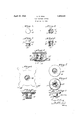
- Figure 1 is a top plan view
- Fig. 2 is a side elevation
- Fig. 3 is a bottom plan view
- Fig. 4 is a vertical section of the improved form of compensating anvil and filler or combination anvil and filler.
- Fig. 5 is a vertical section of the anvil and filler assembled in a tackfastened button having a long shank or hub the restricted portion 9 are the ⁇ laterally yadjustments in case there should be anl unand set upon a piece of fabric.
- Fig. 6 is an enlarged plan view of a blank such as may be used in forming the compensating anvil and filler or the combination anvil and filler.
- Fig. 7 is a top plan view; Fig. 8 is a bottom plan view and Fig. 9 is a side elevation of a modification in which the filler element is extended laterally beyond the tack-receiving chamber.
- Fig. 10 is a vertical section of the anvil and filler of Figs. 7, 8 and9, assembled in a tack-fastened button having a long shank or hub.
- the back of the button has the relatively long hub or shank l, depending from the lateral flange 2, and provided with a bottom 8 made with the opening 4 for the insertion of the tack point.
- Applied to the lateral flange of the tack is any suitable finish cap-5.
- the compensating anvil and filler or the combination anvil and filler designated generally by the reference numeral 6, and havingthejlaterally extended portion 7 provided with a flat top 8 on which the finish cap 5 rests.
- the bottom of the laterally extended portion 7 is constricted, as at 9, thereby forming within the top of the device a ⁇ relatively small tack point receiving and clinching chamber 10.
- Below spread lingers 1l of a length preferably sufficient to rest upon or adjacent to the bottom of -the hub and contacting with the sides Vof the hub.
- the portion 7 is of a diameter to fit comparatively snuglywithin thetop of the hub andthe spread of the fingers l1 is such as to overcome any tendency of displacement or wabbling or waggling.
- These fingers 1l may be more or less resilientk in order to take up usuallyv long pointed or stiff tack used in the assembly orsetting of the button.
- the compensating anvil and filler or combination l anvil and filler may have the upper .portion of the tack point receiving and clinching chamber 12 extended laterally-as at 13 to form in itself the filler element; and ⁇ to compensate for the thickness of thematerialin this form ofthe construction, the center, portion ofthe out- 100 the attaching machine.
- side or top may be indented as at 14:.
- the constricted bottom of the tack clinching and receiving chamber is shown at 9', and the laterally extending lingers are shown at 11.
- the back and cap of the button may be of relatively thin metal, but the compensating anvil and filler or the combination anvil and iller preferably is of thick hard metal that will withstand the blows necessary to clinch the point of the tack 15 against the anvil and thereby to upset or curl it within the tack point clinching and receiving chamber, substantially as indicated at 16, Fig. 5.
- the fingers 11 or 11 may be made more or less long in order to accommodate the device to buttons having hubs of various lengths.
- the part 17 may represent an article on which the button is set.
- the blank shown in Fig. 6 may be drawn or pressed to shape, mere changes in Jforni and size being required to form either type of anvil and filler.
- Vhat I claim is:
- a tack-fastened button having a compensating or combination anvil and filler member, and a shank or hub, said member comprising a portion providing an anvil chamber of less depth than the length of the hub and provided with a constricted opening for the entrance of a tack point and fingers offstanding from said portion, said member adapted to be positioned within the button hub with the top portion adjacent to the top of said hub and its lingers bearing against the inner face of the bottom of said hub to tlhreby position the member axially of the 2.
- a tack-fastened button having a compensating or combination anvil and filler member, and a shank or hub, said member comprising a relatively shallow tack-receiving and clinching chamber provided with a restricted entrance and having depending laterally extending lingers, the upper portion of the said chamber and the entire length of the lingers being confined Within the hub.
- a tack-fastened button having a compensating or combination anvil and filler member, and a shank or hub, said member comprising a relatively shallow tack-receiving and clinching chamber provided with a restricted entrance and having depending laterally extending fingers, the upper portion of the said chamber and the entire length of the fingers being confined within the hub and held against wabbling therein and adapted for use with a long hub.
- a tack-fastened button having a compensating or combination anvil and ller member, and a shank or hub, said member comprising a relatively shallow tack-receiving and clinching chamber provided with a restricted entrance and having depending laterally extending fingers, the upper portion of the said chamber and the entire length of the fingers being confined within the hub, said chamber laterally confined within the hub.
- a tack-fastened button having a compensating or combination anvil and filler member, and a shank or hub, said member comprising a relatively shallow tack-receiving and clinching chamber provided with a restricted entrance and having depending laterally extending fingers, the upper portion of the said chamber and the entire length of the fingers being coniined within the hub, said chamber laterally and axially confined within the hub.
- a tack-fastened button having a shank or hub and a compensating or combination anvil and filler member, said member comprising a relatively shallow tack-receiving and clinching chamber provided with a restricted entrance and having depending laterally extending fingers, a portion of the said chamber and the entire length of the fingers being conlined within the hub, the upper portion of said chamber being laterally extended to form a filler element.
Landscapes
- Footwear And Its Accessory, Manufacturing Method And Apparatuses (AREA)
Description
April 19, 1932. G. A. KING v 1,854,845
TACK FASTENED BUTTON Filed Jan. 2, 1932 Patented Apr. 19, 1932 UNITED STATES PATENT OFFICE GEORGE A. KING, OF WATERBURY, CONNECTICUT, ASSIGNOR T SCOVILL MANUFAC- p TUBING COMPANY, OF .WATERBURY, CONNECTICUT, A CORPORATION 0F CONNECT;-
ICUT
TACK FASTENED BUTTON Application led January 2, 1932. Serial No. 584,516.
The object of this invention is to provide a compensating anvil and filler or a combination anvil and filler for tack-fastened buttons, which may be usefully and eiciently `applied in either an ordinary relatively short hubbed button or a relatively long `hubbed button; these long hubbed buttons being designed to accommodate a modern form of buttonhole which is reinforced and has a relatively thick edge. To place within this `elongated hub or shankthe ordinary type of one piece anvil filler is to offer too deep an anvil chamber to cooperate with the tack and make sure of a perfect upsetting of the tack .15point and close fit thereof in its receiving chamber in the anvil.
There is danger also that the assembled button will have a loose and waggling or wabbling effect and may even twist apart from the tack.
In order to meet the objections noted and others, the present invention consists of a compensating anvil and filler or a combination anvil and filler, designed specially for use in a button having a relatively long shankor hub, but .which is also applicable to a button having a hub or shank of ordinary length, the anvil having a relatively small tack-end clinching and receiving chamber at one end and spread-out fingers Vat the opposite end, which .fingers may be and preferably are resilient and are adapted toengage or Contact with the inner surfaces of the hub or shank, to guide the tack point into the tack chamber and to provide a certain springiness to take up adjustments in case there should be an unusually long pointed or stiiftack'usedin the assembly, as I will proceed now more fully to explain and finally claim.
In the accompanying drawings illustrating the invention, in the several figures of which like parts are similarly designated, Figure 1 is a top plan view; Fig. 2 is a side elevation; Fig. 3 is a bottom plan view and Fig. 4 is a vertical section of the improved form of compensating anvil and filler or combination anvil and filler. Fig. 5 is a vertical section of the anvil and filler assembled in a tackfastened button having a long shank or hub the restricted portion 9 are the `laterally yadjustments in case there should be anl unand set upon a piece of fabric. Fig. 6 is an enlarged plan view of a blank such as may be used in forming the compensating anvil and filler or the combination anvil and filler. y Fig. 7 is a top plan view; Fig. 8 is a bottom plan view and Fig. 9 is a side elevation of a modification in which the filler element is extended laterally beyond the tack-receiving chamber. Fig. 10 is a vertical section of the anvil and filler of Figs. 7, 8 and9, assembled in a tack-fastened button having a long shank or hub.
In Figs. 1 to 5, inclusive, the back of the button has the relatively long hub or shank l, depending from the lateral flange 2, and provided with a bottom 8 made with the opening 4 for the insertion of the tack point. Applied to the lateral flange of the tack is any suitable finish cap-5.
Fitted within the shank or hub is the compensating anvil and filler or the combination anvil and filler, designated generally by the reference numeral 6, and havingthejlaterally extended portion 7 provided with a flat top 8 on which the finish cap 5 rests. The bottom of the laterally extended portion 7 is constricted, as at 9, thereby forming within the top of the device a` relatively small tack point receiving and clinching chamber 10. Below spread lingers 1l of a length preferably sufficient to rest upon or adjacent to the bottom of -the hub and contacting with the sides Vof the hub. The portion 7 is of a diameter to fit comparatively snuglywithin thetop of the hub andthe spread of the fingers l1 is such as to overcome any tendency of displacement or wabbling or waggling. These fingers 1l may be more or less resilientk in order to take up usuallyv long pointed or stiff tack used in the assembly orsetting of the button.
As shown in Figs. 6 to 10 the compensating anvil and filler or combination l anvil and filler may have the upper .portion of the tack point receiving and clinching chamber 12 extended laterally-as at 13 to form in itself the filler element; and` to compensate for the thickness of thematerialin this form ofthe construction, the center, portion ofthe out- 100 the attaching machine.
side or top may be indented as at 14:. The constricted bottom of the tack clinching and receiving chamber is shown at 9', and the laterally extending lingers are shown at 11.
The back and cap of the button may be of relatively thin metal, but the compensating anvil and filler or the combination anvil and iller preferably is of thick hard metal that will withstand the blows necessary to clinch the point of the tack 15 against the anvil and thereby to upset or curl it within the tack point clinching and receiving chamber, substantially as indicated at 16, Fig. 5.
In addition to the adjustment features previously mentioned, it is to be noted that the same function will be observed in making allowance for variations in the adjustment of If, for example, the machine is set for a double thickness of fabric but should be applied to a triple or quadruple thickness, or its equivalent, in especially thick goods, there would undoubtedly be an excessive amount of squeezing between the hub and the tack which would tend to cut into the fabric. The spring-like form of the fingers will take up such extra pressure by collapsing of the filler within the hub and thus avoid the excessive constriction between the tack and the outer surface of the hub.
Moreover, the fingers 11 or 11 may be made more or less long in order to accommodate the device to buttons having hubs of various lengths. Y
In the two forms of the invention there are shown four lingers, but there may be more or fewer of such lingers.
In Fig. 5, the part 17 may represent an article on which the button is set.
The blank shown in Fig. 6 may be drawn or pressed to shape, mere changes in Jforni and size being required to form either type of anvil and filler.
Variations in the details of construction are permissible within the principle of the invention and the scope of the claims following.
Vhat I claim is:
1. A tack-fastened button, having a compensating or combination anvil and filler member, and a shank or hub, said member comprising a portion providing an anvil chamber of less depth than the length of the hub and provided with a constricted opening for the entrance of a tack point and fingers offstanding from said portion, said member adapted to be positioned within the button hub with the top portion adjacent to the top of said hub and its lingers bearing against the inner face of the bottom of said hub to tlhreby position the member axially of the 2. A tack-fastened button, having a compensating or combination anvil and filler member, and a shank or hub, said member comprising a relatively shallow tack-receiving and clinching chamber provided with a restricted entrance and having depending laterally extending lingers, the upper portion of the said chamber and the entire length of the lingers being confined Within the hub.
3. A tack-fastened button, having a compensating or combination anvil and filler member, and a shank or hub, said member comprising a relatively shallow tack-receiving and clinching chamber provided with a restricted entrance and having depending laterally extending fingers, the upper portion of the said chamber and the entire length of the fingers being confined within the hub and held against wabbling therein and adapted for use with a long hub.
4f. A tack-fastened button, having a compensating or combination anvil and ller member, and a shank or hub, said member comprising a relatively shallow tack-receiving and clinching chamber provided with a restricted entrance and having depending laterally extending fingers, the upper portion of the said chamber and the entire length of the fingers being confined within the hub, said chamber laterally confined within the hub.
5. A tack-fastened button, having a compensating or combination anvil and filler member, and a shank or hub, said member comprising a relatively shallow tack-receiving and clinching chamber provided with a restricted entrance and having depending laterally extending fingers, the upper portion of the said chamber and the entire length of the fingers being coniined within the hub, said chamber laterally and axially confined within the hub.
6. A tack-fastened button, having a shank or hub and a compensating or combination anvil and filler member, said member comprising a relatively shallow tack-receiving and clinching chamber provided with a restricted entrance and having depending laterally extending fingers, a portion of the said chamber and the entire length of the fingers being conlined within the hub, the upper portion of said chamber being laterally extended to form a filler element.
In testimony whereof I have hereunto set my hand this 28th day of December, A. D
GEORGE A. KING.
Priority Applications (1)
| Application Number | Priority Date | Filing Date | Title |
|---|---|---|---|
| US584516A US1854845A (en) | 1932-01-02 | 1932-01-02 | Tack fastened button |
Applications Claiming Priority (1)
| Application Number | Priority Date | Filing Date | Title |
|---|---|---|---|
| US584516A US1854845A (en) | 1932-01-02 | 1932-01-02 | Tack fastened button |
Publications (1)
| Publication Number | Publication Date |
|---|---|
| US1854845A true US1854845A (en) | 1932-04-19 |
Family
ID=24337634
Family Applications (1)
| Application Number | Title | Priority Date | Filing Date |
|---|---|---|---|
| US584516A Expired - Lifetime US1854845A (en) | 1932-01-02 | 1932-01-02 | Tack fastened button |
Country Status (1)
| Country | Link |
|---|---|
| US (1) | US1854845A (en) |
-
1932
- 1932-01-02 US US584516A patent/US1854845A/en not_active Expired - Lifetime
Similar Documents
| Publication | Publication Date | Title |
|---|---|---|
| US1554887A (en) | Spoon holder | |
| US1854845A (en) | Tack fastened button | |
| US2303673A (en) | Shelf supporting device | |
| US2125540A (en) | Fastening device | |
| US2049869A (en) | Button | |
| US940738A (en) | Swivel snap-hook. | |
| US1798237A (en) | Button | |
| US2058318A (en) | Sew-on button | |
| US2124313A (en) | Ejector fork | |
| US893237A (en) | Pin and the like. | |
| US1981345A (en) | Snap fastener socket | |
| US1952330A (en) | Heel | |
| US1841739A (en) | Combined filler and anvil for tack-fastened buttons | |
| US1610829A (en) | Button | |
| US3063170A (en) | Replaceable top lift | |
| US1430601A (en) | Button | |
| US1149183A (en) | Tack. | |
| US2071126A (en) | Bail connection | |
| US2061506A (en) | Button | |
| US2091832A (en) | Slide fastener | |
| US1761612A (en) | Separable snap fastener | |
| US935332A (en) | Tire-protective rivet. | |
| US1113211A (en) | Snap-fastener top. | |
| US1467279A (en) | Button for soft collars and other articles | |
| US1489777A (en) | Button |