US1854585A - Combined desk paper weight, calendar, and blotter - Google Patents
Combined desk paper weight, calendar, and blotter Download PDFInfo
- Publication number
- US1854585A US1854585A US490170A US49017030A US1854585A US 1854585 A US1854585 A US 1854585A US 490170 A US490170 A US 490170A US 49017030 A US49017030 A US 49017030A US 1854585 A US1854585 A US 1854585A
- Authority
- US
- United States
- Prior art keywords
- calendar
- blotter
- plate
- paper weight
- supporting sheet
- Prior art date
- Legal status (The legal status is an assumption and is not a legal conclusion. Google has not performed a legal analysis and makes no representation as to the accuracy of the status listed.)
- Expired - Lifetime
Links
- 239000002184 metal Substances 0.000 description 3
- 229920002160 Celluloid Polymers 0.000 description 1
- 238000010276 construction Methods 0.000 description 1
- 230000000994 depressogenic effect Effects 0.000 description 1
- 230000004048 modification Effects 0.000 description 1
- 238000012986 modification Methods 0.000 description 1
- 210000002105 tongue Anatomy 0.000 description 1
Images
Classifications
-
- B—PERFORMING OPERATIONS; TRANSPORTING
- B43—WRITING OR DRAWING IMPLEMENTS; BUREAU ACCESSORIES
- B43M—BUREAU ACCESSORIES NOT OTHERWISE PROVIDED FOR
- B43M9/00—Paper-weights
Definitions
- This invention relates to desk accessories and more particularly to a combined blotter, paper weight and calendar.
- a further object is the provision of a combined blotter, paper weight and calendar which may be readily and cheaply manufactured, at the same time being durable and pleasing in appearance.
- Figure 1 represents a plan view of the device.
- Figure 2 represents a plan view of the main body of the device.
- Figure 3 represents a bottom view of a cover used on the device.
- Figure 4 represents a bottom view of a detent expedient used in connection with the calendar provided for the device.
- Figure 5 represents a sectional view taken on line 55 of Figure 4.
- Figure 6 represents a plan view of the structure shown in Figure 4.
- Figure 7 represents a perspective view of internal elements of the device.
- Figure 8 represents a sectional view taken on the line 88 of Figure 11.
- Figure 9 represents a bottom view of the device with the bottom removed.
- Figure 10 represents a detent element used in the device.
- Figure 11 represents a sectional view taken on the line 1111 of Figure 1.
- Figure 12 represents a side View of the dev1ce.
- the device is shown to include a base member formed from a sheet of metal 13; which has upturned flanges 14to provide sides and its bend portions bent over to provide tubular elements 15.
- the blotter 16 is passed over the underside of the base member and over the tubular elements 15 as is shown in Figure 11.
- a. supporting sheet is shown to comprise a metal plate 17 with upturned flanges 18 and endportions bent over to provide tubular members 19, the generalstructure of the cover member being similar to that of the base; and the cover member is proportioned so that it will fit within the base in a. manner to clamp the ends of the blotter 16 between tubular elements 15 and 19 as shown in Figure 11. 1
- One of the sides 18 has a narrow flange 20 and the supporting sheet 17 is provided with a rectangular aperture 21 and two spaced holes 22.
- Mounted on the base is a trough-like member 23 which has upstanding ends 24 and an integral laterally projecting plate 25, the latter being parallel to plate 23.
- the plate 25 is provided with a pair of holes 26 designed to register with the holes 22.
- the plate 25 Underneath the plate 25 is positioned a flat metal spacing and positioning weight 27 which also has spaced holes 28 in register with the holes 26.
- the plate 23 is provided with a plurality of spaced depressions'29 for a purpose hereinafter described.-
- a calendar 32 is positioned between a flanged frame member 30 and a plate 33.
- the calendar 32 and plate 33 are secured to a resilient plate 34 by means of a rivet 31, the latter projecting above the calendar in order to provide means by which the assembly may be moved along the trough plate 23.
- the resilient plate 34 has downturned resilient tongues 35, one of which carries a rounded projection 36 adapted to enter one of the depressions 29 and resiliently hold the assembly in desired positions.
- the supporting sheet 17, plate 25 and weight 27 are rigidly secured together by means of a U-shaped rivet member 37, which also serves as a handle for the entire accessory, the frictional engagement between the tubular portions 15 and 19 of the base and cover respectively being suflicient to prevent the cover from being Withdrawn from the base when a blotter is mounted thereon.
- the calendar comprises a single celluloid sheet having marked thereon numbers from 1 to 31 and on the first day of each month the assembly shown in Figures 4, 5 and 6, is moved to place the numeral one in register With the proper day of the week, the designations or" the days of the Week being marked on the cover member as shown in Figure 1.
- the calendar assembly is maintained throughout the month in the proper position by the resilient engagement of the rounded projection 36 with the depressed portion 29.
- a desk accessory a supporting sheet having an aperture, a plate attached to and spaced from the supporting sheet, said plate having a plurality of spaced recesses, a flat spring having a lug engageable in the recesses, and a calendar device attached to the spring and slidably mounted between the supporting sheet and plate,said calendar device being visible through the aperture in the supporting sheet.
- a supporting sheet liaving an aperture
- a plate attached to and spaced from the supporting sheet
- a flanged member slidably mounted between the supporting sheet and plate
- a calendar device carried by said flanged member and visible through the aperture in the supporting sheet
- a spring secured to the flanged member and adapted to bear against the plate to hold the flanged member in adjusted position.
- a supporting sheet having an aperture, a plate attached to and spaced from the supportin sheet, a calendar device slidably mounted ietween the supporting sheet and plate, and a resilient plate
Landscapes
- Toilet Supplies (AREA)
Description
April 19, 1932. w c l lNG COMBINED DESK PAPER WEIGHT, CALENDAR, AND BLOTTER Filed Oct. 21, 1930 2 Sheets-Sheet l f INVENTOR if if J ATTORNEY April 19, 1932. w. c. HIERING 1,854,535
COMBINED DESK PAPER WEIGHT, CALENDAR, AND BLOTTER Filed Oct. 21, 1950 2 Sheets-Sheet 2 19 a 5 r 16 w v: a if I 1; 21a
INVENTOR MM ATTORNEY V Patented Apr. 19, 1932 v uNrrEn sreres WILLIAM o. 'HIERING, or NEWARK, NEW JERSEY, Assreironmo :r. E. MERGOT'I' comrain, or NEWARK, NEW JERSEY, A coRroRATIo oE DELAWARE COMBINED DESK PAPER WEIGHT, CALENDAR, Ann ZBLOTTER Application filed October 21,1930. Serial No. 490,170.
This invention relates to desk accessories and more particularly to a combined blotter, paper weight and calendar.
The usual oflice desk is equipped with a paper weight, blotter and a calendar along with other accessories. Obviously, a multiplication or" accessories on a desk is objectionable as they limit the available working space. Inasmuch as a blotter, paper weight and calendar are in the nature of necessities on every desk, it is an object of this invention to combine a blotter, paper weight and calendar into one article and thereby decrease the number of individual accessories which may be scattered over a desk.
A further object is the provision of a combined blotter, paper weight and calendar which may be readily and cheaply manufactured, at the same time being durable and pleasing in appearance.
These and other advantageous objects, which will later appear, are accomplished by the simple and practical construction and arrangement of parts hereinafter described and exhibited in the accompanying drawings, forming part hereof, and in which:
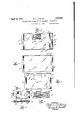
Figure 1 represents a plan view of the device.
Figure 2 represents a plan view of the main body of the device.
Figure 3 represents a bottom view of a cover used on the device.
Figure 4 represents a bottom view of a detent expedient used in connection with the calendar provided for the device.
Figure 5 represents a sectional view taken on line 55 of Figure 4.
Figure 6 represents a plan view of the structure shown in Figure 4.
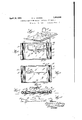
Figure 7 represents a perspective view of internal elements of the device.
Figure 8 represents a sectional view taken on the line 88 of Figure 11.
Figure 9 represents a bottom view of the device with the bottom removed.
Figure 10 represents a detent element used in the device.
Figure 11 represents a sectional view taken on the line 1111 of Figure 1.
Figure 12 represents a side View of the dev1ce.
Referring to the drawings, the device is shown to include a base member formed from a sheet of metal 13; which has upturned flanges 14to provide sides and its bend portions bent over to provide tubular elements 15. The blotter 16 is passed over the underside of the base member and over the tubular elements 15 as is shown in Figure 11.
In Figure 3 a. supporting sheet is shown to comprise a metal plate 17 with upturned flanges 18 and endportions bent over to provide tubular members 19, the generalstructure of the cover member being similar to that of the base; and the cover member is proportioned so that it will fit within the base in a. manner to clamp the ends of the blotter 16 between tubular elements 15 and 19 as shown in Figure 11. 1
One of the sides 18 has a narrow flange 20 and the supporting sheet 17 is provided with a rectangular aperture 21 and two spaced holes 22. Mounted on the base is a trough-like member 23 which has upstanding ends 24 and an integral laterally projecting plate 25, the latter being parallel to plate 23. The plate 25 is provided with a pair of holes 26 designed to register with the holes 22.
Underneath the plate 25 is positioned a flat metal spacing and positioning weight 27 which also has spaced holes 28 in register with the holes 26. The plate 23 is provided with a plurality of spaced depressions'29 for a purpose hereinafter described.-
As shown in Figures 4, 5 and 6, a calendar 32 is positioned between a flanged frame member 30 and a plate 33. The calendar 32 and plate 33 are secured to a resilient plate 34 by means of a rivet 31, the latter projecting above the calendar in order to provide means by which the assembly may be moved along the trough plate 23. The resilient plate 34 has downturned resilient tongues 35, one of which carries a rounded projection 36 adapted to enter one of the depressions 29 and resiliently hold the assembly in desired positions. r
The supporting sheet 17, plate 25 and weight 27 are rigidly secured together by means of a U-shaped rivet member 37, which also serves as a handle for the entire accessory, the frictional engagement between the tubular portions 15 and 19 of the base and cover respectively being suflicient to prevent the cover from being Withdrawn from the base when a blotter is mounted thereon.
In operation, the calendar comprises a single celluloid sheet having marked thereon numbers from 1 to 31 and on the first day of each month the assembly shown in Figures 4, 5 and 6, is moved to place the numeral one in register With the proper day of the week, the designations or" the days of the Week being marked on the cover member as shown in Figure 1.
The calendar assembly is maintained throughout the month in the proper position by the resilient engagement of the rounded projection 36 with the depressed portion 29.
From the above description it will be seen that I have provided an easily manufactured and simple device which includes a blotter, calendar and paper weight, the device being durable and positive in its action. The only manipulations of the device necessary are the monthly adjustment of the calendar and the changing of the blotter from time to time as may be desired The foregoing disclosure is to be regarded as descriptive and illustrative only, and not as restrictive or limitative of the invention, of which obviously an embodiment may be constructed including many modifications without departing from the general scope herein indicated and denoted in the appended claims.
Having thus described my invention, What I claim as new and desire to secure by Letters Patent, is:
1. In a desk accessory, a supporting sheet having an aperture, a plate attached to and spaced from the supporting sheet, said plate having a plurality of spaced recesses, a flat spring having a lug engageable in the recesses, and a calendar device attached to the spring and slidably mounted between the supporting sheet and plate,said calendar device being visible through the aperture in the supporting sheet.
2. In a desk accessory, a supporting sheet liaving an aperture, a plate attached to and spaced from the supporting sheet, a flanged member slidably mounted between the supporting sheet and plate, a calendar device carried by said flanged member and visible through the aperture in the supporting sheet, and a spring secured to the flanged member and adapted to bear against the plate to hold the flanged member in adjusted position.
3. In a desk accessory, a supporting sheet having an aperture, a plate attached to and spaced from the supportin sheet, a calendar device slidably mounted ietween the supporting sheet and plate, and a resilient plate
Priority Applications (1)
| Application Number | Priority Date | Filing Date | Title |
|---|---|---|---|
| US490170A US1854585A (en) | 1930-10-21 | 1930-10-21 | Combined desk paper weight, calendar, and blotter |
Applications Claiming Priority (1)
| Application Number | Priority Date | Filing Date | Title |
|---|---|---|---|
| US490170A US1854585A (en) | 1930-10-21 | 1930-10-21 | Combined desk paper weight, calendar, and blotter |
Publications (1)
| Publication Number | Publication Date |
|---|---|
| US1854585A true US1854585A (en) | 1932-04-19 |
Family
ID=23946886
Family Applications (1)
| Application Number | Title | Priority Date | Filing Date |
|---|---|---|---|
| US490170A Expired - Lifetime US1854585A (en) | 1930-10-21 | 1930-10-21 | Combined desk paper weight, calendar, and blotter |
Country Status (1)
| Country | Link |
|---|---|
| US (1) | US1854585A (en) |
Cited By (1)
| Publication number | Priority date | Publication date | Assignee | Title |
|---|---|---|---|---|
| USD572763S1 (en) * | 2007-07-06 | 2008-07-08 | Gabe Neiser | Desk pad |
-
1930
- 1930-10-21 US US490170A patent/US1854585A/en not_active Expired - Lifetime
Cited By (1)
| Publication number | Priority date | Publication date | Assignee | Title |
|---|---|---|---|---|
| USD572763S1 (en) * | 2007-07-06 | 2008-07-08 | Gabe Neiser | Desk pad |
Similar Documents
| Publication | Publication Date | Title |
|---|---|---|
| US1217243A (en) | Plat-filing cabinet. | |
| US1851013A (en) | Bill clip | |
| US2658773A (en) | Golf score cardholder | |
| US1560493A (en) | Holder | |
| US1854585A (en) | Combined desk paper weight, calendar, and blotter | |
| US1983443A (en) | Memorandum support for cradle type telephones | |
| US2117668A (en) | Book holder | |
| US2220469A (en) | Holding clip for partition plates | |
| US387284A (en) | Device for measuring the thickness of lumbier | |
| US2094796A (en) | Writing instrument clip with interchangeable initials | |
| US717247A (en) | Credit-accounting appliance. | |
| US1172382A (en) | Telephone attachment. | |
| US1752952A (en) | Display device | |
| US1327317A (en) | Perpetual calendar | |
| US1689479A (en) | Attachable match box | |
| US1880165A (en) | Memorandum calendar | |
| US1213185A (en) | Memorandum-pad holder for desk-telephones. | |
| US1580770A (en) | Collapsible daily-memorandum calendar | |
| US2428388A (en) | Memorandum holder | |
| US1613492A (en) | Watch holder | |
| US1396428A (en) | Paper or bill file | |
| US2169067A (en) | Attaching device for miner's lamp | |
| US1192054A (en) | Calendar. | |
| US1566525A (en) | Paper holder | |
| US1008509A (en) | Calendar-pad support. |